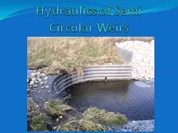
/
Hydraulics of Semi Circular Weirs Hydraulics of Semi Circular Weirs

Hydraulics of Semi Circular Weirs - PowerPoint Presentation

mitsue-stanley
mitsue-stanley . @mitsue-stanley
Follow
352 views
Uploaded On 2018-09-22

Hydraulics of Semi Circular Weirs - PPT Presentation

Hydraulics of Semi Circular Weirs QCLH t 32 L Effective Length of Weir H t Total Head Still Pool H V 2 2g Energy Grade Line H amp V measured 3H upstream from weir ID: 675820

circular semi weirs hydraulics semi circular hydraulics weirs weir freeboard drop coefficient structures aluminum logical paper asae section

Share:

Link:

Embed:

Download Presentation from below link

Download Presentation The PPT/PDF document "Hydraulics of Semi Circular Weirs" is the property of its rightful owner. Permission is granted to download and print the materials on this web site for personal, non-commercial use only, and to display it on your personal computer provided you do not modify the materials and that you retain all copyright notices contained in the materials. By downloading content from our website, you accept the terms of this agreement.


Presentation Transcript

Slide1

Hydraulics of Semi Circular WeirsSlide2

Hydraulics of Semi Circular Weirs

Q=CLH

t

3/2

L = Effective Length of Weir

H

t

= Total Head (Still Pool)

= H + V

2

/2g = Energy Grade Line

H & V measured 3H upstream from weir

C = Weir Coefficient

Commonly used coefficient for these structures is 2.72

2.72????Slide3

Hydraulics of Semi Circular Weirs

C = Weir Coefficient

1980 ASAE paper “Corrugated Aluminum Drop Structures for Erosion Control” by Blum (NRCS) &

DeGraff

(Kaiser Aluminum) states:

The basic C

, 3.1,

is modified to allow for freeboard, using SCS criteria of 3.1/1.14, or C = 2.72.

Kaiser Aluminum Structural Plate Drop Structures manual (DP-109 Edition 3) also specifies this

C =

3.1

= 2.7

1.14

Modification to allow for freeboardSlide4

Hydraulics of Semi Circular Weirs

Where does the 1.14 come from?

NEH Section 11, Drop Spillways,

p.3.7 -

FreeboardSlide5

Hydraulics of Semi Circular Weirs

NEH Section 11, p.3.7

… it is convenient and logical to consider freeboard in terms of increased weir discharge capacity. It also seems logical to assume that the required freeboard should be some function of the

overfall

through the drop spillway, F, since the possible damage due to failure increases with an increase in F.

Reasonable increase in discharge capacity

= 0.10 + 0.01F

= 0.10 + 0.01(4) Assuming a 4’ drop

= 0.14Slide6

Hydraulics of Semi Circular Weirs

The use of a weir coefficient of 2.72 has nothing to do with a semi circular weir layout. It is just the traditional coefficient of 3.1 modified to provide freeboard.Slide7

Hydraulics of Semi Circular WeirsSlide8

Hydraulics of Semi Circular WeirsSlide9

Hydraulics of Semi Circular Weirs

Weir Control Flow

Q = C

1

L(2g)

1/2

H

3/2Slide10

Hydraulics of Semi Circular Weirs

Example

W = 20’

L = 43.1’

F = 4’

B = 5.7’

Wc

= 24’

Wc

/L = .55

→C1 = 0.21

Q = 0.21*(2g)

1/2

*(H)

3/2Slide11

Hydraulics of Semi Circular WeirsSlide12

Hydraulics of Semi Circular Weirs

Example

W = 20’

L = 43.1’

F = 4’

B = 5.7’

Wc

= 35’

Wc

/L = 0.8

→C1 = 0.34

Q = 0.34*(2g)

1/2

*(H)

3/2Slide13

Hydraulics of Semi Circular WeirsSlide14

Hydraulics of Semi Circular Weirs

Tailwater

submergence effect also considered in Becker’s ASAE paper.

Too confusing to address today.

Jean Sandstrom (Des Moines, NRCS) is developing a standard drawing for the 6’ version of the drop. She also put together a spreadsheet to assist in hydraulic analysis. Still, a lot of table look ups