/
pcs pcs pcs pcs Top Panel  Nail Leg Screw Wooden Dowel pcs pcs pcs Power Pin CamLock Nut pcs pcs pcs pcs Top Panel  Nail Leg Screw Wooden Dowel pcs pcs pcs Power Pin CamLock Nut

pcs pcs pcs pcs Top Panel Nail Leg Screw Wooden Dowel pcs pcs pcs Power Pin CamLock Nut - PDF document

mitsue-stanley
mitsue-stanley . @mitsue-stanley
Follow
568 views
Uploaded On 2014-11-23

pcs pcs pcs pcs Top Panel Nail Leg Screw Wooden Dowel pcs pcs pcs Power Pin CamLock Nut - PPT Presentation

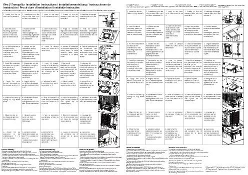
STEP 3 Fix Drawer Slide7 to PanelDEusing Screw8 Note Please make sure leftright side of Drawer Slide7 before attach it 1x4pcs 8x2pcs 8x2pcs STEP 2 Fix Drawer Slide7to PanelHusing Screw8 Note Please make sure leftright side of Drawer Slide7 before at ID: 15437

STEP Fix Drawer

Share:

Link:

Embed:

Download Presentation from below link

Download Pdf The PPT/PDF document "pcs pcs pcs pcs Top Panel Nail Leg Scre..." is the property of its rightful owner. Permission is granted to download and print the materials on this web site for personal, non-commercial use only, and to display it on your personal computer provided you do not modify the materials and that you retain all copyright notices contained in the materials. By downloading content from our website, you accept the terms of this agreement.


Presentation Transcript

Assembly Instruction Customer ServiceTel/Fax: 281.500.9372Toll Free: 773.299.8111 (Mon - Fri 9am - 5pm)Email: support@furinno.com its Space. its Budget Writing Desk Tools Required Recomm. 2 PersonApprox. 30 minutes USEFUL HINTS BEFORE YOU START: 1. Read each step carefully before starting.2. It is important that each step is performed in correct order to avoid difficulties.3. Identify, sort and count the parts before assembly.4. Assemble your furniture on packaging cardboard to prevent scratch or damage.5. Clean the product with mild cleanser using soft damped cloth. Do not use harsh or abrasive cleanser.6. Using uncompatible hardware might cause damage to product. 12318pcs6pcs6pcs A1pcsTop Panel 1Nail LegNoHardware ListQtyNoQtyParts ListScrewWooden Dowel 4566pcs6pcs16pcsPower PinCam-Lock NutCam-Lock Screw 781pcsDrawer SlideShort Screw BC1pcs1pcsLeft Side PanelTop Panel 2 DEF1pcs1pcs2pcsShelf PanelCenter PanelRight Side Panel GH2pcs1pcsKeyboard PanelCross Bar I2pcsBack Panel ABCDEGHII G FF ISTEP 4 Attach Panel(F)to Panel(D)using Screw(1).STEP 3 Fix Drawer Slide(7) to Panel(D)&(E)using Screw(8).Note: Please make sure left/right side of Drawer Slide(7) before attach it. DFF1 (1)x4pcs DE8877 (8)x2pcs (8)x2pcsSTEP 2 Fix Drawer Slide(7)to Panel(H)using Screw(8).STEP 1 1.1 Insert Dowel(2)and Cam-Lock Nut(4)to Panel(C)(D)&(E),as shown. H87 (8)x4pcs 87 ABEDC (5)x2pcs (5)x4pcs (4)x2pcs (2)x2pcs Arrow on Cam-Lock Nut(4) should be polnting 4 STEP 6 6.1 Attach Panel(C)to assembled parts using Screw(1).6.2 Install Nail Leg(3)to the bottom of Panel(C)(D)&(E)using hammer.STEP 5 Attach Panel(G)to Panel(D)&(E)using Screw(1). DGGEFF (1)x8pcs DGGECFF1 (1)x4pcs (3)x6pcs STEP 8 8.1 Attach Panel(A)to Panel(D)using Screw(1). STEP 7 Attach Back Panel(I)to the back position of Panel(C)&(D)using Power Pin(6). DC(I)(I) (6)x16pcs Cable Hole DAE4 (1)x2pcs WARNING:�This unit has been designed to support themaximum loads shown. Exceeding theseload limits could cause sagging, instability,product collapse, and/or serious injury.�DO NOT allow children to climb on unit. 9.1 Attach Panel(B)to Panel(C)&(D)and tighten Cam-Lock Nut(4)using screwdriver.9.2 Slide the Keyboard Panel(H)to the assembled unit. STEP 9Recommended Maximum Weight *Unit in Pound(lbs) 10 15 10 10 BCDEH 47