/
Extending The Life Of Subsea Wells With Long Tiebacks By Fo Extending The Life Of Subsea Wells With Long Tiebacks By Fo

Extending The Life Of Subsea Wells With Long Tiebacks By Fo - PowerPoint Presentation

myesha-ticknor
myesha-ticknor . @myesha-ticknor
Follow
402 views
Uploaded On 2017-03-19

Extending The Life Of Subsea Wells With Long Tiebacks By Fo - PPT Presentation

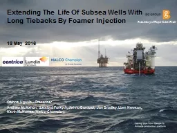
18 May 2016 Obinna Ugoala Presenter Andrew McMahon Gatsbyd Forsyth Jishnu BordoIoi Jon Bradley Liam Newson Kevin McNamee NalcoChampion Subsidiary of Royal Dutch Shell 2 Introduction Armada Hub ID: 526318

foaming foamer rate injection foamer foaming injection rate loading liquid wellbore periodic choke ftht restart prod kcl foam field

Share:

Link:

Embed:

Download Presentation from below link

Download Presentation The PPT/PDF document "Extending The Life Of Subsea Wells With ..." is the property of its rightful owner. Permission is granted to download and print the materials on this web site for personal, non-commercial use only, and to display it on your personal computer provided you do not modify the materials and that you retain all copyright notices contained in the materials. By downloading content from our website, you accept the terms of this agreement.


Presentation Transcript

Slide1

Extending The Life Of Subsea Wells With Long Tiebacks By Foamer Injection

18 May 2016

Obinna Ugoala – Presenter

Andrew McMahon, Gatsbyd Forsyth, Jishnu BordoIoi, Jon Bradley, Liam Newson, Kevin McNamee (Nalco-Champion)

Subsidiary of Royal Dutch ShellSlide2

2Slide3

Introduction: Armada Hub

Located in the Central Northsea250km NE of AberdeenDiscovery: 1980

Start of Development: 1994Start of Production: 1997 Originally Gas field DevelopmentSubsequent tie-in of Oilfields (subsea)

Maria (2008)Rev (2009)Northwest Seymour (2011)Gaupe or Pi (2012)Varg (2013)All fields Productions are by Depletion driveWater Depth: 90mPlatform – block 22/5b

3Slide4

Armada Hub Fields Layout

4Slide5

Challenge: Overcoming Liquid Loading Issues During Late Life

Problem

Location in theFlow Conduit

ManifestationConsequenceWellboreHydrostatic Column GrowthRate Reduction / Well dying

Flowline and/or Pipeline

SluggingProcess Upset (Separation Challenge)

Additional Backpressure Rate Reduction

5

Late Field/Well Life Production Challenge

I

ncrease in Liquid-to-Gas Ratio (LGR) and associated low reservoir pressure

Prod. Choke

FTHT

Wellbore DeltaP

FL DeltaP

FTHP

Wellbore Liquid Loading

Prod. Choke

FTHT

FL DeltaP

FTHP

Flowline/Pipeline LoadingSlide6

Remediation: Options to Overcome Liquid Loading

6

System Natural Lift Improvement

Well Focussed

Well interventions (e.g: stimulation –

where opportunity exists to improve IPR

)

W

orkover (e.g: sidetrack, velocity string) –

where potential exists and cost justifiable

Flowline/Pipeline Focussed

Increase in well count

(where opportunity and economics agree)

Third party gas

(where opportunity exists)

Artificial Lift Options

Gas

lift

syste

m

Pumps

Rod

pumps, hydraulic jet pumps, electrical submersible pumps

, subsea multiphase pumps,

FoamingApplication of foaming agents (possibly most cost-effective, having the right setup)Slide7

Subsea Wells Foaming Application: Areas F

or ConsiderationIdentification of Problem Location

Wellbore, flowline/pipeline or bothWhile a pipeline liquid loading problem can be resolved via wellbore foamer injection; wellbore liquid loading problem may not be resolved via flowline/pipeline foamer injection

Identification of The Right Type of Foaming AgentSuitability for gas well, oil well or bothFoam stability in any combination of the three phases (gas, oil and water)Ionic state of the foaming agent compatibility with the formation rock wettability (core testing if unsure)Identification of Foaming Agent (Foamer) Conveyance PathUmbilical AvailabilitySpare umbilical(s) – Maria case

Umbilical for Injected Chemical that is no-longer required (Chemicals Compatibility check and/or flushing) - Gaupe caseMixing (or Simultaneous injection) of foamer and other injected chemical (

Chemicals Compatibility check and minimum effective concentration/loading for each chemical necessary) Wetted Path Compatibility CheckCompatibility with piping and completion components material(s)7Slide8

Determination of Foamer Loading (Concentration/Rate Requirement)Dosage/Volume for batch Treatment

Start-up of well might require batch dosing followed by periodic/continuous foamingInjection Rate for periodic or continuous foamer applicationMinimum foamer rate/concentration to maintain stable foam in the production conduit (Lab tests and field iteration)

Determination of minimum injection rate to maintain stable downhole flow; very vital (modelling and field trials)

Determination of the Foaming Strategy (this will be Well condition/stage dependent)Periodic (Intermittent)Used for well kick-offs (sometimes)Support well flow when rate (or FTHT) falls below a set limit and stop after a period of injectionContinuous injectionUsed for well kick-off

Inject foamer so long as the well is openFoam Handling at SurfaceSelection of appropriate Anti-foam (Lab. tests and field trials)

Guidance on Anti-foam injection rate (Lab. tests and field iteration)Selection of appropriate Anti-foam injection point (preferably upstream of the Separator to allow for some mixing time)8

Subsea Wells Foaming Application: Areas For ConsiderationSlide9

Subsea Wells Foaming Application: Areas For Consideration

Foam Impact on Separators/Separation Process (Poor OiW/ WiO)Spill/Carry OversIncreased transient liquid returns (especially at start-up)

Impaired interface level (poor level control)Possible improvement in level control with nucleonic devicesIncreased solids (fines, sand, organics and/or sludge) returns into the separators that might reduce residence time/efficiency

Strategy for possibly more vessel monitoring (thermographics)/cleaning frequencyConsideration of Prevailing Logistical and/or Operational Constraints/RequirementsExport Route Waiver (where applicable)Chemical Permits – foamer and anitfoam (e.g DECC, FPS or other authorities; where applicable

)Material shipment requirementsPlatform space availabilityStocking of additional chemical inventories

9Slide10

Some Field Results

10Slide11

Gaupe South

Well Type: Subsea Horizontal well with smart completion (ICVs)Separate ICVs for Oil and Gas legsPipeline: 8 inch diameter by 7.4 Km length

Oil Rate: 150 - 400 stb/dGas Rate: 2 - 4 mmscf/dWater Rate: 20 – 50 stb/dReservoir Pressure: 65 barg

Reservoir Temperature: 127 degCReservoir Depth: 3280m / 3475m (MD)11

DHCI Line

(Foamer Path)

Gaupe

South Foaming Project

Liquid Loading Location

Wellbore

Foaming

Strategy

Periodic and later

changed to Continuous

Foamer

Selection

Nonionic surfactant and suitable

for both Gas and Oil well conditions (Foaming Agent A)

Foamer

loading

Foamer

diluted in 4% KCl (initially MEG).

Batch dosing plus Periodic/continuous foamer loading for well restart.

Periodic/Continuous

injection

Foamer: 100 ml/min

KCl: 200 ml/min

2015 Production

GainApproximately

40%Slide12

Gaupe South Foaming – Periodic Injection

12

First Prod. With Foamer (Aug 01, 2015)

Well Kick-off with Foamer:

Batch Foamer Dosage + Periodic Injection

FTHP

Prod. Choke

FTHT

Well Kick-off with foamer

Periodic InjectionsSlide13

Gaupe South Foaming – Continuous Injection

13

Foamer Turned off for 1.5 days

FTHP

Prod. Choke

FTHTSlide14

Maria Terrace

Well Type: Subsea Horizontal well with Slotted linersPipeline: 12 inch diameter by 11 Km length

Oil Rate: 100 - 300 stb/dGas Rate: 1 - 3 mmscf/dWater Rate: 1 – 20 stb/d

Reservoir Pressure: 130 barg Reservoir Temperature: 149 degCReservoir Depth: 4140 m (MD)14

Maria Terrace Foaming Project

Liquid Loading LocationPipelineFoaming StrategyPeriodic to deliquify pipelineFoamer Selection

Nonionic surfactant and suitable for both Gas and Oil well conditions (Foaming Agent A)Foamer loading

Foamer

diluted in 4% KCl (Initially MEG).

(Not

required for well restart)

Periodic

injection

Foamer: 100 ml/min

KCl: 200 ml/min

2015 Production Gain

Approximately

90%

DHCI Line

(Foamer Path)Slide15

Maria Terrace Foaming – Periodic Injection

15

Start of FL Foaming

(April 17, 2015)

Foaming Episodes for additional FL clearing

Foaming Episodes for FL Clearing

Foaming Episodes for FL Clearing

FTHP

FTHTSlide16

Lessons Learnt

16Slide17

Lessons Learnt

Better Chance of Success if Foamer is Injected Downhole (DH)Both wellbore and flowline/pipeline liquid loading can be simultaneous managed as shown in Maria and Gaupe case histories

Consider the benefit of installing DH chemical injection lines in new wells that can be used later in the well/field life to maximise recovery Increased Activity in Sand Monitors

(more sand production alerts)Although more solids are returned, sand erosion risk is lower as foamed systems lack velocity necessary for erosion due to the artificially high viscosity of foamsCaution with Transient Time of the Flow ConduitBe ready to manage possible large slug arrivals (This can strain vessels capacity)Ensure to have an estimate of the arrival time for each well foam

Important when more then one well is foamed as not to overwhelm the vessels with the high foam concentration; especially, in the case of well start-ups with batch doses (Best to stager restarts)

17Slide18

Lessons Learnt

Possible Excursions in Topside Separation Performance (Particularly OiW)

Requires careful monitoring by operations teamArmada benefits from ancillary media-based water polishing

unitLabour and running cost implicationsWatch out for Umbilical/Downline Content Siphoning (can lead to failed restart) Hydrostatic Difference in wellbore and Downline of the Injection Path18

FTHP

Prod. Choke

FTHT

DHCIV Closed

DHCIV Opened

Foamer injected but well failed to restart; period used to refill umbilical content

Foamer

Batch DosingSlide19

Lessons Learnt

In Foamer Injection System with Simultaneous Injection of Foamer and Diluent; Always Remember that

Concentration Change(s) will take Umbilical/Downline Volume/time to Effect (reach DH)Allow enough time to implement change(s) and monitor response

Some Well Kick-offs (Restarts) with Foamer can Take Longer Time / be More Challenging than Others (Driven by)Prevailing well LGR and remaining reservoir energyFoamer loading (Concentration/Rate)19

FTHP

Prod. Choke

FTHT

DHCIV Opened

FTHP

Prod. Choke

FTHT

DHCIV Opened

FBHP

Fast Restart Response

Slow Restart ResponseSlide20

20

Best PracticeSlide21

Best Practices

Foaming ImplementationConsider having a Pilot (or Test) phase before setting up a permanent system or scheme This will help in fine turning of the system (foaming) and also provide input data for the permanent setup.

Well Kick-off with FoamerBatch Dose Well and Soak for 12 to 24 hours prior to RestartThe batch dosing allows for

sufficient foamer quantity to match the standing column of liquid in the wellbore following Well SI (target 0.2% foamer concentration). Necessary for stable foam generation at start-up.Soak period allows for reasonable mixing of the foamer and standing liquid column by diffusion (short period Well agitation can enhance the mixing process)21Slide22

Best Practices

Start Continuous Foamer Injection Ahead of Well Opening1 to 2 hours prior to opening the Well to ensure the foamer is available on demand at the wellbore entry pointSiphoning of some of the umbilical content has been experienced to occur

(leads to failed well restart)Avoid Neat Foamer Injection

(where possible) – Deliver the Foamer with a Diluent (e.g x% KCl)Achievement of DH minimum stable injection rate at manageable foamer volumesCost managementManagement of umbilical content freezing risk (geographical region dependent)22

Test Label

DescriptionIncumbentNeat Foaming Agent A (with MEG/Water mix)Sample 3

Foamer A with 2% KCl @ 75:25 mixture ratioSample 6Foamer A with 4% KCl @ 75:25 mixture ratio

Sample 11

Foamer

A with 4% NaCl @ 50:50 mixture ratio

Sample

12

Foamer A with

4% NaCl @ 75:25 mixture ratio

Viscosity vs Temp. Trend of Foaming Agent A Dilutions with KCl or NaClSlide23

Best Practices

Revise Well Beanup ProcedureTarget slightly aggressive Tree choke opening whilst the Topside choke is used to manipulate the Riser as Slug-catcher (where slug-catcher is not available)

Small choke increments (5 – 10%) every (5 -15 min); where possibleFocus on maintaining liquid momentum in the wellbore during Well restartsShut-in Well for Couple of Days of Pressure Buildup (PBU)

Might be necessary in cases of repeated failed restart attempts5 days to 2 weeks might be necessary depending on well’s LGRAllows some wellbore liquids to drain back into the reservoirRe-establishes static equilibrium23Slide24

Acknowledgements / Thank You / Questions

The authors would like to thank the management of BG Group (Royal Dutch Shell Subsidiary), Centrica, Lundin and Nalco-Champion for support and permission to share this document/knowledge

24