/
ISSN   Copyright to IJIRSET www ISSN   Copyright to IJIRSET www

ISSN Copyright to IJIRSET www - PDF document

myesha-ticknor
myesha-ticknor . @myesha-ticknor
Follow
458 views
Uploaded On 2014-11-28

ISSN Copyright to IJIRSET www - PPT Presentation

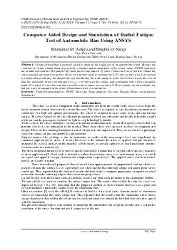
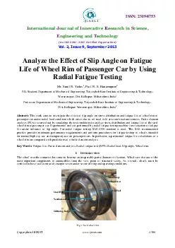
ijirsetcom 4309 Analyze the ffect of lip ngle on atigue ife of heel im of assenger ar by sing adial atigue esting Mr Sunil N Yadav Prof N S Hanamapure PG Student Department of Mechanical Engineering Tatyasaheb Kore Institute of Engineering T ID: 17911

ijirsetcom 4309 Analyze the ffect

Share:

Link:

Embed:

Download Presentation from below link

Download Pdf The PPT/PDF document "ISSN Copyright to IJIRSET www" is the property of its rightful owner. Permission is granted to download and print the materials on this web site for personal, non-commercial use only, and to display it on your personal computer provided you do not modify the materials and that you retain all copyright notices contained in the materials. By downloading content from our website, you accept the terms of this agreement.


Presentation Transcript

ISSN: 2319 - 8753 I nternational J ournal of I nnovative R esearch in S cience, E ngineering and T echnology ( An ISO 3297: 2007 Certified Organization) Vol. 2, Issue 9, September 2013 Copyright to IJIRSET www .ijirset.com 4309 Analyze the E ffect of S lip A ngle on F atigue L ife of W heel R im of P assenger C ar by U sing R adial F atigue T esting Mr. Sunil N . Yadav 1 , Prof. N. S . Hanamapure 2 P.G. Student, Department of Mechanical Engineering, Tatyasaheb Kore Institute of Engineering & Technology, Warananagar, Dist - Kolhapur, Maharashtra, India 1 Professor, Department of Mechanical Engineering, Tatyasaheb Kore Institute of Engineering & Technology, Dist - Kolhapur, Warananaga r, Maharashtra, India 2 Abstract : This work aims to investigate the effect of slip angle on stress distribution and fatigue life of wheel rim of passenger car under radial load condition which arises due to off road field area and road unevenness . Finite element analysis (FEA) is carried out by simulating the test conditions to analyze stress distribution and fatigue life of the steel wheel rim of passenger car. Experimental analysis performed by radial fatigue testing machine for evaluation of fati gue life under influence of slip angle. For radial fatigue testing SAE J328 standard is used. This SAE r ecommended practice provides minimum performance requirements and uniform procedures for fatigue testing of wheels intended for normal highway use and t emporary use on passenger cars. In particular, experimental fatigue life calculations of a wheel rim are compared with predictions of a f inite element analysis. Key Words: Fatigue life, Finite element analysis, Radial f atigue t est (RFT), Radial load, Slip a ngle, Wheel rim. I. I NTRODUCTION The wheel over the centuries has come to become an inseparable part of human civilization. Wheels are also one of the most important components of automobiles from the view point of structural safety. As a result, wheels m ust be certified to have sufficient safety margins even under severe driving and operating conditions. Fig. 1: Steel wheel rim ISSN: 2319 - 8753 I nternational J ournal of I nnovative R esearch in S cience, E ngineering and T echnology ( An ISO 3297: 2007 Certified Organization) Vol. 2, Issue 9, September 2013 Copyright to IJIRSET www .ijirset.com 4310 Moreover, since other requirements such as lighter weight or more attractive design make the configuration of the wheel more complicated and sophisticated, it has become necessary to perform rigorous strength evaluations of the wheel in detail when a new wheel design is developed. A well designed wheel is the foundation which adds strength, stabil ity and durability to a tyre. Hence, the increased urge to make them safer and reliable. As a safety related components, the wheel must fulfil its function reliably throughout the entire life of vehicle. The total weight of a car is balanced with a vertica l reaction force from the road through the tyre. This load constantly compresses the wheel radially. While the car is running, the radial load becomes a cyclic load with the rotation of the wheel. Hence, the evaluation of wheel fatigue strength under radia l load is an important performance characteristic for structural integrity . II. WHEEL RIM NOMENCLATURE The w heel rim is actually the name for the cylindrical part where the tyre is installed. A wheel is the name for the combination between the rim and disc plate. Once the disc plate is installed inside the cylinder this assembly becomes a wheel or wheel rim. (1) Wheel rim or wheel: Wheel is generally composed of rim and disc. (2) Rim: This is a part where the tyre is installed. It is outermost radial part of the wheel serves to accommodate the tyre. (3) Disc: This is a part of the rim where it is fixed to the axle hub. It serves as the interface between rim and hub. For car wheels, th e disc is pressed and provided with ventilation holes around the circumference. Ventilation holes are provided in wheel rim for cooling purpose. To provide space for the brake and distributes stresses uniformly, the contour from the mounting face to the st iffening bulge is shaped. The mounting face with centering pilot hole and concentrically arranged stud hole is located in the center of disc. Wheel rim is bolted to hub w ith the stud holes. Fig. 2 : Wheel rim nomenclature (4) Offset: This is a distance b etween wheel mounting surfaces where it is bolted to hub and the centerline of rim. (5) Flange: The flange is a part of rim which holds the both beads of the tyre. This forms the axial restraining face for the tyre bead and absorbs the forces generated by tyre pressure and the axial stress on the tyre. The part of a rim that supports the tyre bead in a lateral direction; the linear distance between the two rim flanges is termed rim width. ISSN: 2319 - 8753 I nternational J ournal of I nnovative R esearch in S cience, E ngineering and T echnology ( An ISO 3297: 2007 Certified Organization) Vol. 2, Issue 9, September 2013 Copyright to IJIRSET www .ijirset.com 4311 (6) Bead Seat: Bead seat comes in contact with the bead face and is a part of rim which holds the tyre in a radial direction i.e. it is the portion of the wheel rim below the rim flange providing radial support to the bead of the tyre. (7) Hump: It is bump what was put on the bead seat for the bead to prevent the tyre fro m sliding off the rim while the vehicle is moving. (8) Well: This is a part of rim with depth and width to facilitate tyre mounting and removal from the rim. Rim size designation For this paper here use wheel rim model 5.5J X 14 means 5.5 – Rim width (in ch) J – Flange shape 14 – Rim diameter (inch) III. SLIP ANGLE OF WHEEL It is an angle between wheel plane and direction of travel. Slip angle is the angle at which the moving tyre is presented to the road when viewed in plan. It is important to note that slip angle only exists when the vehicle is in motion. When wheel rolls with the slip angle (α) the lateral force generated due to the distribution of shear stress in the contact patch between wheel and road. Slip angle forces are typically more than camber forces for a particular angle, and are thus the more important aspect for vehicle dynamics. Fig. 3 : Forces and moments due to slip angle. In fact, modest slip angles are 'good' as tyres generate progressively more grip with increasing slip angles, alt hough up to definable limit where after no further grip is generated. Thereafter, increasing slip angles are 'bad', and the tyre will tend to loose grip. Therefore, it should be apparent that if the slip angles for the front and rear tyres are the same th en the tyres front and rear are ge nerating similar levels of grip. The car will steer essentially as if there was no slip angle at all i.e. neutral cornering. If the rear slip angle is larger than the front one you have a condition known as over - steer whil e if the front slip angle is larger, the condition known as under - steer results. ISSN: 2319 - 8753 I nternational J ournal of I nnovative R esearch in S cience, E ngineering and T echnology ( An ISO 3297: 2007 Certified Organization) Vol. 2, Issue 9, September 2013 Copyright to IJIRSET www .ijirset.com 4312 IV. FINITE ELEMENT ANALYSIS Generating CAD model is first step towards CAE analysis of any product. In the present case, CAD model of the complete wheel rim has been generated using CATIA V5R17 software. The CAD model of the wheel rim used for analysis is shown in Fig 4 . Fig. 4 : CAD model of wheel rim Fig. 5 : Mesh model of wheel rim Finite element models of the wheel have been created in OPTISTRUCT using HYPERMESH v 9.0. For fatigue life prediction Msc.Fatigue v 2005 use. The CAD model in IGES format is imported in Hyper Mesh for the preparation of FE model. M eshing is performed on s urface by using shell element and these elements are offset on other surface by “ELEMENT OFFSET” process. These shell elements converted in solid brick element by “LINEAR SOLID” command. The three dimensional models are used hexahedral or brick elements. T hese elements are allowed three translations only, so all rotations are ignored in meshed rim model. Two hexahedral elements were used at the thickness of the rim Section. Fig. 6 : Mesh model of w heel rim with tyre Fig. 7: Applied loading condition of wheel rim ISSN: 2319 - 8753 I nternational J ournal of I nnovative R esearch in S cience, E ngineering and T echnology ( An ISO 3297: 2007 Certified Organization) Vol. 2, Issue 9, September 2013 Copyright to IJIRSET www .ijirset.com 4313 Tyre mounts on rim bead seat and tyre is modeled by shell coat i.e. by using shell element. In FE modeling tyre is taken because force is transfer to rim through tyre. Here in this FE modeling layer of shell element is taken on rim because crack is initiated from the surface of rim. The rim was constrained from rotation and translation at the bearing opening and the bolt cir cle. Given radial load apply on the wheel rim; this load is vertical in nature. Total radial load is 9 .32KN which apply through RBE - 2 element. Fig. 8: Constrain applied to wheel rim. Pressure loa d on rim due to tyre air pressure was also applied for radial load case. Problem was solved in OPTISTRUCT and Computer processing time grew to nearly three hours to complete a standard run. A. Steps involved in FE Analysis 1) Used brick mesh i.e. hexahedral element for wheel rim and shell mesh for the tyre. 2) To show the contact between rim and tyre Gap elements were used. 3) All DOF were restricted at center for boundary condition. 4) Material with mechanical properties closest to the given material is sele cted from the fatigue material database and used for life prediction. 5) Radial load apply on tyre. 6) Pressure load on rim due to tyre air pressure was also applied TABLE 1: MESH QUALITY CRITERIA Sr. No. Quality Parameter Allowable Min / Max 1 Minimum Side Length 5 2 Maximum Side Length 20 3 Maximum Aspect Ratio 5 4 Maximum Warpage Angle 15 5 Minimum Quad Internal Angle 45 6 Maximum Quad Internal Angle 135 7 Minimum Tria Internal Angle 15 8 Maximum Tria Internal Angle 120 9 Percent of Triangular Elements 5 ISSN: 2319 - 8753 I nternational J ournal of I nnovative R esearch in S cience, E ngineering and T echnology ( An ISO 3297: 2007 Certified Organization) Vol. 2, Issue 9, September 2013 Copyright to IJIRSET www .ijirset.com 4314 TABLE 2: FINITE ELEMENT MODEL SUMMARY OF THE WHEEL No. of parts 3 No. of node 52079 No. of Element 76093 No. of Material 2 No. of Properties 5 V. EXPERIMENTAL ANALYSIS SAE has several fatigue test specification for wheel. These specifications are based on the radial and cornering loads a wheel receiving during road uses. The original industry wide fatigue test specifications were the SAE J328 for passenger car and light truck steel wheels. A variety of test factors and cycles are used to allow effective evaluation of the fatigue properties of the wheels. Fig. 9 : Schematics showing fatigue test conditions The equipment consists of driven rotatable drum with a smooth surface wider than the loaded tyre. The drum axis is parallel to the axis of the test wheel. The test wheel and tyre provide loading normal to the surface of drum and in line radially with the center of test wheel and the drum. The test wheel is fixed to the hub by nuts with a suitable torque specified by ve hicle or wheel manufacturer. This test simulates the rolling action of the wheel on a road by bringing it into contact with a rotating drum. With this, it is also possible to make the wheel camber and skew to create an extra axial load, such as occurs in c ornering. After a set period of running time, the wheel is inspected for possible cracks. The test specimen can be evaluated in accordance with the position, length, type and number of cracks. In general, failure occurs as a result of the gradual loss of a ir through cracks. Other typical fractures site occurs at the ventilation holes and stud holes. As a safety related components, the wheel must fulfill its function reliability throughout the entire life of the vehicles. The objective of every test is to s imulate the common loads the wheel will encounter. The number of load cycles the wheel will withstand before cracks occur or the wheel fails completely ultimately provides valuable information about its reliability in subsequent use. A decisive process in applying the results of trials to practical situations lies in measuring the loadings which occur under actual driving conditions and which lead to cyclical stresses in the metal fatigue . Generally the test criteria are for the wheel to complete a minimum number of cycles or miles prior to test termination. The test termination is an inability to support load due to disc crack, loose fasteners, or loss of inflation pressure due to fatigue crack is identified in some specifications. Other specifications use the loss of inflation pressure or inability to sustain the load as the main determination ISSN: 2319 - 8753 I nternational J ournal of I nnovative R esearch in S cience, E ngineering and T echnology ( An ISO 3297: 2007 Certified Organization) Vol. 2, Issue 9, September 2013 Copyright to IJIRSET www .ijirset.com 4315 TABLE 3: TEST SPECIFICATION Parameter Details Wheel size/Model 5.5J X 14 Radial Load 9.32 KN (950 Kg) No. of specified cycles 330000 Air pressure 3 bar Tyre size 175/70R14 Bolt clamping torque 86 NM Wheel bolt details M12 X 1.25 Test speed 60 - 80 kmph VI. RESULT & DISCUSSION A. Effect on stress distribution due to slip angle TABLE 4: STRESS DISTRIBUTION ON WHEEL RIM AT SLIP ANGLE POSITION S Sr. No Location on wheel Stress (MPa) 0° Slip 3° Slip 5° Slip 1 Maximum stress 248 292 398 2 Stud hole 220 229 341 3 Stiffening buldge 165 194 258 4 Ventilation hole 123 166 198 5 Bead seat 111 127 142 6 Rim flange 93 100 119 7 Rim well 59 83 97 Fig . 10 : Stress distribution on wheel rim at 0° slip angle ISSN: 2319 - 8753 I nternational J ournal of I nnovative R esearch in S cience, E ngineering and T echnology ( An ISO 3297: 2007 Certified Organization) Vol. 2, Issue 9, September 2013 Copyright to IJIRSET www .ijirset.com 4316 Graph 1 : Variation in stress distribution due to slip angle at various location of disc area. Graph 2 : Variation in stress distribution due to slip angle at various location of rim area. Above graphs shows that the stresses at 0°, 3° and 5° slip angles are much higher in the disc area (stud hole, stiffening buldge and ventilation hole) than the rim area (bead seat, rim flange and rim well). The stresses in the wheel rim increases as slip angle increase i.e. the stresses induced in wheel rim are directly proportional to slip angle. B. Effect on fatigue life due to slip angle TABLE 5: FEA RESULTS FOR FATIGUE LIFE OF WHEEL RIM DUE TO SLIP ANGLE. Sr.No. Angle (degree) Maximum stress (MPa) Fatigue life (cycles) 1 0° slip 248 4.84* 10 5 2 3° slip 292 4.25* 10 5 3 5° slip 398 4.05* 10 5 220 229 341 165 194 258 123 166 198 0 50 100 150 200 250 300 350 400 0 ° 3 ° 5 ° Stress(Mpa) Slip Angle(degree) Stud hole Stiffening buldge Ventilation hole 111 127 142 93 100 119 59 83 97 0 20 40 60 80 100 120 140 160 0 ° 3 ° 5 ° Stress(Mpa) Slip Angle(degree) Bead seat Rim flange Rim well ISSN: 2319 - 8753 I nternational J ournal of I nnovative R esearch in S cience, E ngineering and T echnology ( An ISO 3297: 2007 Certified Organization) Vol. 2, Issue 9, September 2013 Copyright to IJIRSET www .ijirset.com 4317 According to above results from MSC fatigue software at 0 ° , 3° and 5° slip angle, fatigue strength of wheel rim decreases with increase in slip angle. Fig. 1 1: Failure location of wheel rim Graph 3 : Variation in fatigue life of wheel rim due to change in slip angle TABLE 6 : RADIAL FATIGUE TEST RESULTS FO R FATIGUE LIFE OF WHEEL RIM DUE TO SLIP ANGLE . Sr.No. Angle (degree) Fatigue life (cycles) Observations 1 0°slip 5.00* 10 5 No Crack,Test Stopped 2 3°slip 5.00* 10 5 No Crack,Test Stopped 3 5°slip 5.00* 10 5 No Crack,Test Stopped Above results from radial fatigue test show that fatigue strength of wheel rim at 0 ° , 3° and 5° slip angle are above specified limits. 4.84 4.25 4.05 3.6 3.8 4 4.2 4.4 4.6 4.8 5 0 ° 3 ° 5 ° Fatigue Life (cycles)*10 5 Slip Angle (degrees) Slip angle Vs fatigue life ISSN: 2319 - 8753 I nternational J ournal of I nnovative R esearch in S cience, E ngineering and T echnology ( An ISO 3297: 2007 Certified Organization) Vol. 2, Issue 9, September 2013 Copyright to IJIRSET www .ijirset.com 4318 VII. CONCLUSION The finite element analysis as well as experimental analysis of passenger car wheel rim performed for radial load with the effect of slip angle on stress distribution and fatigue life, the following are the observations.  The stresses are much higher in the disc area than the rim area.  The likely failures locations identified in the wheel rim by finite ele ment analysis are stud holes, stiffening buldge and ventilation holes.  The stresses in wheel rim are directly proportional to slip angle as shown in table 7 i.e. the life of wheel rim decreases as slip angle and camber angle increase. TABLE 7 : STRESS SUM MERY BY FINITE ELEMENT ANALYSIS Slip Angle Stresses [MPa] Disc Parts Rim Parts Stud hole Stiffening buldge Ventilation hole Bead seat Rim flange Rim well 0 ° 220 165 123 111 93 59 3 ° 229 194 166 127 100 83 5 ° 341 258 198 142 119 97  Finite element analysis shows that the fatigue strength of 5.5J X 14 wheel at 0°,3° and 5 ° slip angle is above specified limit (330000 cycles).  The tests carried out by radial fatigue testing machine also reveals that fatigue strength of wheel at 0° , 3° and 5 ° slip angle is satisfactory and well above the specified limit.  After analysis it is observed that there is some area where the stresses are very low like rim well, rim flange and some disc part. So there is further scope for reduction in sections a nd minimize the weight of wheel with optimum design considerations.  In case that stresses determined by simulation are excessive, corrective measures must be applied to the design, e.g. changing to a higher strength material. In most cases, however, geome tric modifications are sufficient. Computed results can be considerably influenced by adjusting the radii of the stiffening bulges or the size and shape of the ventilation hole. REFERENCES [1] Vatroslav Grubisic, Gerhard Fischer, "Automotive Wheels, Method and Procedure for Optimal Design and Testing," SAE Technical Paper Series, 830135, 1983. [2] Miloslav Reisner, Richard I . DeVries, "Finite Element Analysis and Structural Optimization of Vehicle Wheels," SAE Technical Paper Series, 830133, 1983. [3] J. Stearns, T. S. Srivatsan, X. Gao, P. C. Lam, “Understanding the Influence of Pressure and Radial Loads on Stress and Displacement Response of a Rotating Body: The Automobile Wheel” Hindawi Publishing Corporation, International Journal of Rotating Machiner y Volume , Artic le ID 60193, pp. 1 – 8, 2006 . [4] S.C. Kerr, D.L. Russell, U.S. Patel, N.W.M. Bishop, “FE - Based Wheel Fatigue Analysis Using MSC.FATIGUE.” 1st MSC Worldwide Automotive Conference, Munich, Germany , September 20 - 22, 1999 [5] P. Ramamurthy Raju, B. Satyanarayana, K. R amji, K. Suresh Babu,” Evaluation of fatigue life of aluminum alloys wheels under radial loads.” Enginee ring Failure Analysis 14, pp. 791 – 800 , 2007 . [6] D. H. Wright, "Test Methods for Automotive Wheels," I Mech E Conference Publications, Conference Code 03757, 1983. [7] John K instler, ” The science and methodology of SAE wheel fatigue test specifications” SAE tech nical publication 2005 - 01 - 1826,2005 [8] Mehmet Firat, Recep Kozan, Murat Ozsoy, O. Hamdi Mete, “ Numerical modeling and simulation of wheel radial fatigue tests .” Enginee ring Failure Analysis 16, pp. 1533 – 1541 , 2009. [9] SAE, "Wheels - Passenger Car and Light Truck Performance Requirements and Test Procedures - SAE J328", Jun 1994.