/
Misfire Detection Monitor  The misfire detection monitor is an on-boar Misfire Detection Monitor  The misfire detection monitor is an on-boar

Misfire Detection Monitor The misfire detection monitor is an on-boar - PDF document

myesha-ticknor
myesha-ticknor . @myesha-ticknor
Follow
428 views
Uploaded On 2015-09-07

Misfire Detection Monitor The misfire detection monitor is an on-boar - PPT Presentation

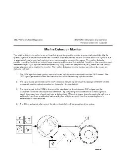
2007 PCED On Board Diagnostics SECTION 1 Description and Operation Procedure revision date 03292006 Misfire Detection Monitor Misfire Monitor Operation There are 3 different misfire monitoring ID: 123286

2007 PCED Board Diagnostics

Share:

Link:

Embed:

Download Presentation from below link

Download Pdf The PPT/PDF document "Misfire Detection Monitor The misfire d..." is the property of its rightful owner. Permission is granted to download and print the materials on this web site for personal, non-commercial use only, and to display it on your personal computer provided you do not modify the materials and that you retain all copyright notices contained in the materials. By downloading content from our website, you accept the terms of this agreement.


Presentation Transcript

Misfire Detection Monitor The misfire detection monitor is an on-board strategy designed to monitor engine misfire and identify the specific cylinder in which the misfire has occurred. Misfire is defined as lack of combustion in a cylinder due to absence of spark, poor fuel metering, poor compression, or any other cause. The misfire detection monitor is enabled only when certain base engine conditions are first satisfied. Input from the engine coolant temperature (ECT) or cylinder head temperature (CHT), intake air temperature (IAT), mass air flow (MAF) sensors is required to enable the monitor. The misfire detection monitor is also carried out during an on-demand self-test. 1.The PCM synchronized ignition spark is based on information received from the CKP sensor. The CKP signal generated is also the main input used in determining cylinder misfire. 2.The input signal generated by the CKP sensor is derived by sensing the passage of teeth from the crankshaft position wheel mounted on the end of the crankshaft. 3.The input signal to the PCM is then used to calculate the time between CKP edges and the crankshaft rotational velocity and acceleration. By comparing the accelerations of each cylinder event, the power loss of each cylinder is determined. When the power loss of a particular cylinder is sufficiently less than a calibrated value and other criteria are met, then the suspect cylinder is determined to have misfired. 4.The MIL is activated after one of the above tests fail on 2 consecutive drive cycles. 2007 PCED On Board Diagnostics SECTION 1: Description and Operation Procedure revision date: 03/29/2006 Misfire Detection Monitor Misfire Monitor Operation There are 3 different misfire monitoring technologies used. They are low data rate (LDR) and high data rate (HDR), and neural network misfire. The LDR system is capable of meeting the federal test procedure monitoring requirements on most engines and is capable of meeting the full-range of misfire monitoring requirements on 4-cylinder engines. The HDR system is capable of meeting the full-range of misfire monitoring requirements on 6 and 8 cylinder engines. The neural network misfire detection system improves detection ranges and cylinder identification for a wider range of misfire patterns on some 8, 10, and 12 cylinder vehicles. The HDR on these engines meets the full-range of misfire phase-in requirements specified in the OBD regulations. All engines except the 6.8L V-10 are full-range capable. All software allows for detection of any misfires that occur 6 engine revolutions after initially cranking the engine. This meets the OBD requirement to identify misfires within 2 engine revolutions after exceeding the warm drive, idle RPM. Low Data Rate System (LDR) The LDR misfire monitor uses a low data rate crankshaft position signal, one position reference signal at 10 degrees before top dead center (BTDC) for each cylinder event. The PCM calculates the crankshaft rotational velocity for each cylinder from this crankshaft position signal. The acceleration for each cylinder can then be calculated using successive velocity values. The changes in overall engine RPM are removed by subtracting the median engine acceleration over a complete engine cycle. The resulting deviant cylinder acceleration values are used in evaluating misfire in the General Misfire Processing section below. High Data Rate System (HDR) The HDR misfire monitor uses a high data rate crankshaft position signal, 18 position references per crankshaft revolution. This high resolution signal is processed using 2 different algorithms. The first algorithm is optimized to detect hard misfires on one or more continuously misfiring cylinders. The low pass filter filters the high-resolution crankshaft velocity signal to remove some of the crankshaft torsional vibrations that degrade signal to noise. Two low pass filters are used to enhance detection capability – a base filter and a more aggressive filter to enhance single-cylinder capability at higher RPM. This significantly improves detection capability for continuous misfires on single cylinders at redline. The second algorithm, called pattern cancellation, is optimized to detect low rates of misfire. The algorithm learns the normal pattern of cylinder accelerations from the mostly good firing events and is then able to accurately detect deviations from that pattern. Both the hard misfire algorithm and the pattern cancellation algorithm produce a deviant cylinder acceleration value, which is used in evaluating misfire in the General Misfire Algorithm Processing section below. Due to the high data processing requirements, the HDR algorithms could not be implemented in the PCM microprocessor. They are implemented in a separate chip in the PCM called an AICE chip. The PCM microprocessor communicates with the AICE chip using a dedicated serial communication link. The AICE chip sends the cylinder acceleration values back to the PCM microprocessor for additional processing as described below. Lack of serial communication between the AICE chip and the PCM microprocessor, or an inability to synchronize the crankshaft or camshaft sensors inputs sets a DTC. DTC P0606 is set if there is a lack of serial communication between the AICE chip and the PCM microprocessor. DTC P1336 is set if there is an inability to synchronize the crank or camshaft sensor inputs. This change was made to improve diagnosis. DTC P0606 generally results in PCM replacement while DTC P1336 points to a camshaft sensor that is out of synchronization with the crank. Profile correction software is used to learn and correct for mechanical inaccuracies in crankshaft tooth spacing under de-fueled engine conditions (requires 3 decelerations from 97 to 64 km/h (60 to 40 mph) with no-braking after the keep alive memory (KAM) has been reset). If the KAM has been reset, the PCM microprocessor initiates a special routine which computes correction factors for each of the 18 (or 20) position references and sends these correction factors back to the AICE chip to be used for subsequent misfire signal processing. These learned corrections improve the high RPM capability of the monitor. The misfire monitor is not active until a profile has been learned. Neural Network System The neural network misfire monitor uses a dedicated microprocessor in the PCM along with crankshaft position, (36-tooth wheel or 40-tooth wheel on a V-10), camshaft position, and engine load to determine engine misfire. A neural network is a different way of computing that uses a large number of simple processing elements with a high degree of interconnection to process complex information. The processing elements have adaptive characteristics (coefficients) that must be learned through a process called training. During training, the network is fed a sample set of data that consists of the inputs along with the desired output (misfire/no misfire). The network coefficients are recursively optimized so that the correct output is generated from the set of inputs and error is minimized. Once the coefficients have been learned, the network can process real data. The neural network size is 23 nodes and 469 coefficients. The engine off natural vacuum evaporative system monitor also uses the same microprocessor. Profile correction software is also used on neural network system to learn and correct for mechanical inaccuracies in crankshaft tooth spacing under de-fueled engine conditions (requires up to three 60 to 40 mph no-braking decelerations after Keep Alive Memory has been reset). These learned corrections improve the high RPM capability of the monitor. The misfire monitor is not active until a profile has been learned. Generic Misfire Processing The acceleration that a piston undergoes during a normal firing event is directly related to the amount of torque that cylinder produces. The calculated piston/cylinder acceleration value(s) are compared to a misfire threshold that is continuously adjusted based on inferred engine torque. Deviant accelerations exceeding the threshold are conditionally labeled as misfires. The calculated deviant acceleration value(s) are also evaluated for noise. Normally, misfire results in a nonsymmetrical loss of cylinder acceleration. Mechanical noise, such as rough roads or high RPM/light load conditions, will produce symmetrical acceleration variations. Cylinder events that indicate excessive deviant accelerations of this type are considered noise. Noise-free deviant acceleration exceeding a given threshold is labeled a misfire. The number of misfires are counted over a continuous 200 revolution and 1,000 revolution period. The revolution counters are not reset if the misfire monitor is temporarily disabled such as for negative torque mode. At the end of the evaluation period, the total misfire rate and the misfire rate for each individual cylinder is computed. The misfire rate is evaluated every 200 revolution period (Type A) and compared to a threshold value obtained from an engine speed/load table. This misfire threshold is designed to prevent damage to the catalyst due to sustained excessive temperature 871°C (1,600°F) for Pt/Pd/Rh conventional washcoat, 899°C (1,650°F) for Pt/Pd/Rh advanced washcoat and 982°C (1,800°F) for Pd-only high tech washcoat. If the misfire threshold is exceeded and the catalyst temperature model calculates a catalyst mid-bed temperature that exceeds the catalyst damage threshold, the MIL blinks at a 1 Hz rate while the misfire is present. If the threshold is again exceeded on a subsequent driving cycle, the MIL is illuminated. If a single cylinder is indicated to be consistently misfiring in excess of the catalyst damage criteria, the fuel injector to that cylinder may be shut off for a period of time to prevent catalyst damage. Up to 2 cylinders may be disabled at the same time. This fuel shut-off feature is used on many 8-cylinder engines and some 6-cylinder engines. It is never used on a 4-cylinder engine. Next, the misfire rate is evaluated every 1,000 revolution period and compared to a single (type B) threshold value to indicate if the emission-threshold exceeded, which can be either a single 1,000 over-rev event from startup or 4 subsequent 1,000 over-rev events on a drive cycle after start-up. Many vehicles will set DTC P0316 if the type B threshold is exceeded during the first 1,000 revolutions after engine startup. This DTC is stored in addition to the normal P03xx DTC that indicates the misfiring cylinder. Profile Correction Profile correction software is used to learn and correct for mechanical inaccuracies in the crankshaft position wheel tooth spacing. Since the sum of all the angles between the crankshaft teeth must equal 360 degrees, a correction factor can be calculated for each misfire sample interval that makes all the angles between individual teeth equal. To prevent any fueling or combustion differences from affecting the correction factors, learning is done during deceleration-fuel cutout. The correction factors are learned during closed-throttle, non-braking, de-fueled decelerations in the 97 to 64 km/h (60 to 40 mph) range after exceeding 97 km/h (60 mph) (likely to correspond to a freeway exit condition). In order to minimize the learning time for the correction factors, a more aggressive deceleration-fuel cutout strategy may be employed when the conditions for learning are present. The corrections are typically learned in a single deceleration, but can be learned during up to 3 such decelerations. The mature correction factors are the average of a selected number of samples. A low data rate misfire system will typically learn 4 such corrections in this interval, while a high data rate system will learn 36 or 40 in the same interval (data is actually processed in the AICE chip). In order to assure the accuracy of these corrections, a tolerance is placed on the incoming values such that an individual correction factor must be repeatable within the tolerance during learning. This is to reduce the possibility of learning corrections on rough road conditions which could limit misfire detection capability. Since inaccuracies in the wheel tooth spacing can produce a false indication of misfire, the misfire monitor is not active until the corrections are learned. In the event of battery disconnection or loss of keep alive memory (KAM), the correction factors are lost and must be relearned. If the software is unable to learn a profile after three, 97 to 64 km/h (60 to 40 mph) deceleration cycles, DTC P0315 is set. Misfire Monitor Specifications Misfire monitor operation: DTCs P0300 to P0310 (random and specific cylinder misfire), P1336 (crankshaft/camshaft sensor range/performance), P0606 (control module processor), P0315 (crankshaft position system variation not learned), P0316 (misfire detected on startup [first 1000 revolutions]). The monitor execution is continuous, misfire rate calculated every 200 or 1,000 revolutions. The monitor does not have a specific sequence. The CKP and CMP sensors have to be operating correctly to run the monitor. The monitoring duration is the entire driving cycle (see disablement conditions below). Typical misfire monitor entry conditions: Entry condition minimum/maximum time since engine start-up is 0 seconds, engine coolant temperature is -7°C to 121°C (20°F to 250°F), RPM range is (full-range misfire certified, with 2 revolution delay) 2 revolutions after exceeding 150 RPM below drive idle RPM to redline on tach or fuel cutoff, profile correction factors learned in KAM are Yes, and the fuel tank level is greater than 15%. Typical misfire temporary disablement conditions: Closed throttle deceleration (negative torque, engine being driven), Fuel shut-off due to vehicle-speed limiting or engine-RPM limiting mode, and a high rate of change of torque (heavy throttle tip-in or tip out) The profile learning operation includes DTC P0315 - unable to learn profile in three, 97 to 64 km/h (60 to 40 mph) decelerations; monitor execution is once per KAM reset; The monitor sequence: profile must be learned before the misfire monitor is active; The CKP and CMP sensors are required to be OK; AICE communication errors, CKP/CMP in synch. The monitoring duration is 10 cumulative seconds in conditions (a maximum of three, 97 to 64 km/h (60 to 40 mph) de-fueled decelerations). Typical profile learning entry conditions: Entry conditions from minimum to maximum: Engine in deceleration-fuel cutout mode for 4 engine cycles the brakes are not applied, the engine RPM is 1,300 to 3,700 RPM, the change is less than 600 RPM, the vehicle speed is 48 to 112 km/h (30 to 70 mph), and the learning tolerance is 1%.