/
SILOXA FAKA Gas Cleaning System SILOXA FAKA Gas Cleaning System

SILOXA FAKA Gas Cleaning System - PDF document

naomi
naomi . @naomi
Follow
352 views
Uploaded On 2021-08-20

SILOXA FAKA Gas Cleaning System - PPT Presentation

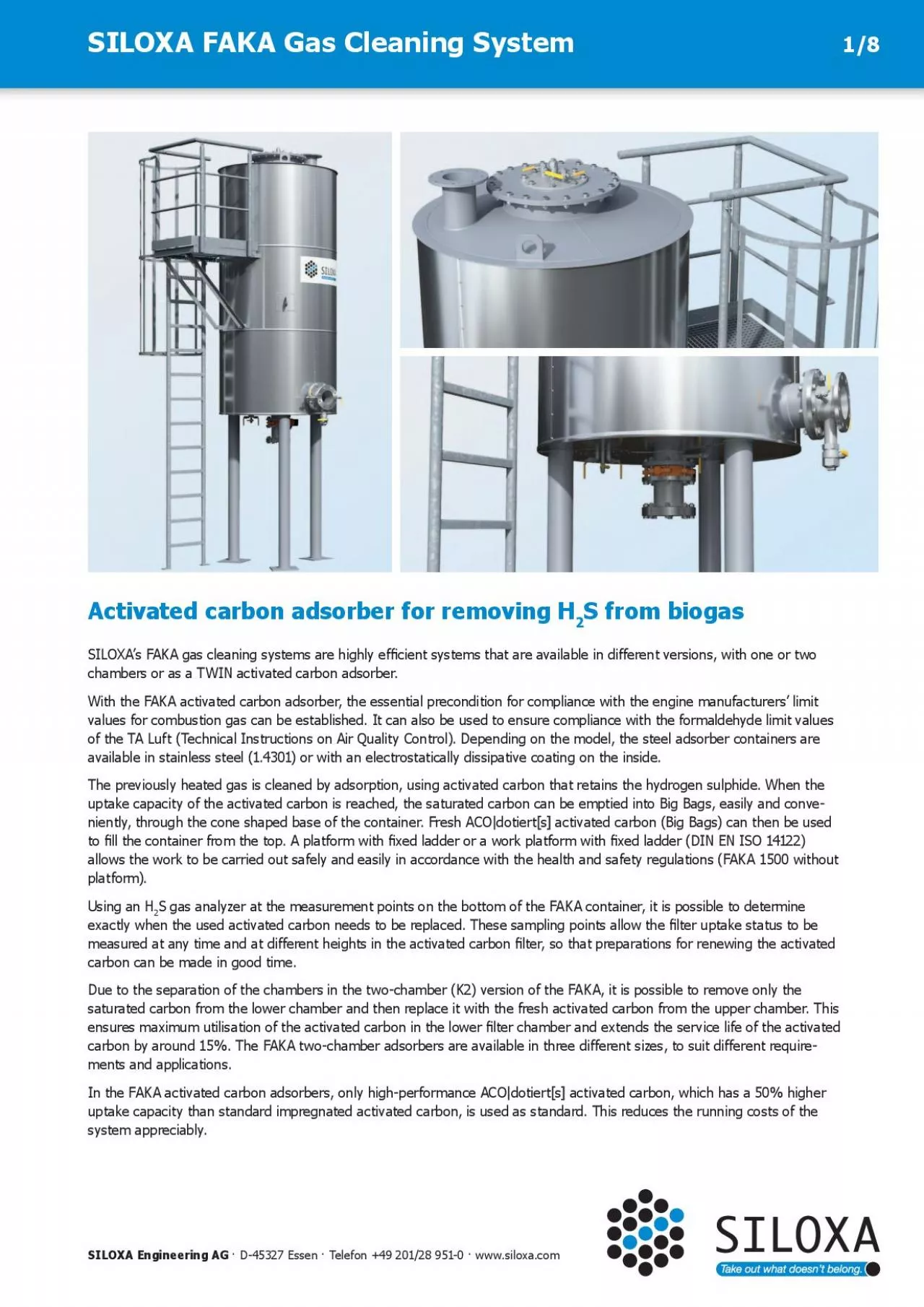
Activated carbon adsorber for removing H2S from biogas SILOXA Engineering AG D45327 Essen Telefon 49 20128 9510 wwwsiloxacomSILOXAs FAKA gas cleaning systems are highly efx00660069cient systems ID: 867726

gas carbon mbar activated carbon gas activated mbar x00660069 000 siloxa faka 150 max 500 x0066006c 900 200 steel

Share:

Link:

Embed:

Download Presentation from below link

Download Pdf The PPT/PDF document "SILOXA FAKA Gas Cleaning System" is the property of its rightful owner. Permission is granted to download and print the materials on this web site for personal, non-commercial use only, and to display it on your personal computer provided you do not modify the materials and that you retain all copyright notices contained in the materials. By downloading content from our website, you accept the terms of this agreement.


Presentation Transcript

1 SILOXA FAKA Gas Cleaning System Activate
SILOXA FAKA Gas Cleaning System Activated carbon adsorber for removing H 2 S from biogas SILOXA Engineering AG · D-45327 Essen · Telefon +49 201/28 951-0 · www.siloxa.com SILOXA’s FAKA gas cleaning systems are highly ef�cient systems that are available in different versions, with one or two chambers or as a TWIN activated carbon adsorber. ith the FAKA activated carbon adsorber, the essential precondition for compliance with the engine manufacturers’ limit values for combustion gas can be established. It can also be used to ensure compliance with the formaldehyde limit values of the TA Luft (Technical Instructions on Air Quality Control). Depending on the model, the steel adsorber containers are available in stainless steel (1.4301) or with an electrostatically dissipative coating on the inside. Th e previously heated gas is cleaned by adsorption, using activated carbon that retains the hydrogen sulphide. When the - niently, through the cone shaped base of the container. Fresh ACO|dotiert[s] activated carbon (Big Bags) can then be used to �ll the container from the top. A platform with �xed ladder or a work platform with �xed ladder (DIN EN ISO 14122) allows the work to be carried out safely and easily in accordance with the health and safety regulations (FAKA 1500 without platform). U sing an H 2 S gas analyzer at the measurement points on the bottom of the FAKA container, it is possible to determine exactly when the used activated carbon needs to be replaced. These sampling points allow the �lter uptake status to be measured at any time and at different heights in the activated carbon �lter, so that preparations for renewing the activated carbon can be made in good time. D saturated carbon from the lower chamber and then replace it with the fresh activated carbon from the upper chamber. This ensures maximum utilisation of the activated carbon in the lower �lter chamber and extends the service life of the activated ca

2 rbon by around 15%. The FAKA two-chamber
rbon by around 15%. The FAKA two-chamber adsorbers are available in three different sizes, to suit different require - ments and applications. In the FAKA activated carbon adsorbers, only high-performance ACO|dotiert[s] activated carbon, which has a 50% higher uptake capacity than standard impregnated activated carbon, is used as standard. This reduces the running costs of the system appreciably. 1/8 Make optimal use of the activated carbon with the convenient FAKA system Sizes/net capacity Type descriptionNet capacityDiameterHeight 2000 K2 Steel 2 x 1,000 l1,270 mm5,034 mm 3000 K1 Steel 3,000 l1,270 mm5,034 mm 6000 K2 Steel 2 x 3,000 l1,900 mm6,999 mm 7000 K1 Steel 7,000 l1,900 mm6,999 mm 1500 K1E 1,500 l1,220 mm2,514 mm 3000 K2E 2 x 1,500 l1,270 mm9,980 mm* 6000 K2E 2 x 3,000 l1,900 mm9,980 mm* 7000 K1E 7,000 l1,900 mm9,980 mm* 3000 K2E TWIN 2 x 1,500 l + 2 x 1,500 l1,270 mm9,980 mm* 6000 K2E TWIN 2 x 3,000 l + 2 x 3,000 l1,900 mm9,980 mm* 7000 K1E TWIN 2 x 7,000 l + 2 x 7,000 l1,900 mm9,980 mm* * Height with crane SILOXA FAKA Gas Cleaning System SILOXA Engineering AG · D-45327 Essen · Telefon +49 201/28 951-0 · www.siloxa.com Issued: 05/2016, subject to technical modi�cations. 2/8 Features the �lter system guarantees long service life of the oxidation catalysts signi�cant lengthening of CHP maintenance intervals prevention of deposits in the combustion chamber high availability of gas utilisation system, operational reliability, low maintenance opportunity for upgrading with further options – easy replacement of activated carbon with Big Bags Consumptio n costs – the activated carbon consumption is determined by the H 2 S load and the gas quantity – the adsorber is optimised for quick and easy activated carbon replacement, to keep wage costs and downtimes as low as possible – large adsorber volumes reduce speci�c replacement costs because the greater the quantity of activated carbon replaced, the lower the speci�c costs for

3 transport, wages and downtimes packing
transport, wages and downtimes packing of activated carbon in Big Bags reduces transport costs S ervi ce – SIL OXA offers a full range of services throughout Europe for the operation of gas cleaning systems with activated carbon adsorbers, from delivering the activated carbon to full service. F AKA Steel steel construction with electrostatically dissipative coating basic features two gas connections (gas inlet and outlet) DN 150 PN10, FAKA 6000K1 & FAKA 7000K1 DN 200 PN 10 inspection opening DN 500 connecting piece with ball valves for inertisation and taking gas samples shut-off valve for emptying activated carbon DN 150 ladder with cage and platform or work platform with handrail thermal insulating mineral wool 50 mm and aluminium sheet jacket F AKA Stainless Steel stainless steel construction (1.4301) basic features two gas connections (gas inlet and outlet) DN 150 PN10 (FAKA 1500 K1E), otherwise DN 200 PN10 inspection opening DN 500 connecting piece with ball valves for inertisation and taking gas samples shut-off valve for emptying activated carbon DN 150 SILOXA FAKA Gas Cleaning System SILOXA Engineering AG · D-45327 Essen · Telefon +49 201/28 951-0 · www.siloxa.com Issued: 05/2016, subject to technical modi�cations. 3/8 Hydrogen sulphide uptake is easily tested at the three measurement points. Technical description ladder with cage and platform or work platform with handrail (except for FAKA 1500 K1) thermal insulating mineral wool 50 mm and aluminium sheet jacket crane unit with winch mechanism and electric chain hoist (650 kg lifting capacity) galvanised steel supporting structure TWIN FAKA stainless steel construction (1.4301) basic features uninterruptible operation possible gas connections (gas inlet and outlet) DN 200 PN 10 depending on �ow rate inspection opening DN 500 connecting piece with ball valves for inertisation and taking gas samples shut-off valve for emptying activated carbon DN 150 thermal insulating mineral wool 50 mm and aluminium sheet jacket

4 ladder with cage and platform or work p
ladder with cage and platform or work platform with handrail crane unit with winch mechanism and electric chain hoist (650 kg lifting capacity) galvanised steel supporting structure De�agration 2 �ame arresters �ame arrester EC type examination certi�cation as per Directive 94/9/EC in accordance with ATEX 95 and EN 12874 equipped with PT100 resistance thermometer Gas heating �anged tube bundle heat exchanger for heating biogas, material in contact with gas media 1.4571 pressure resistance, gas-side 0.5 bar (gauge) pressure resistance, jacket-side 6 bar (gauge) gas connection depending on �ow rate – heating connection 1“ hot water supply temperature 700 kg/h, 70 to 90°C, provided by customer integration in gas supply is the responsibility of the customer SILOXA FAKA Gas Cleaning System SILOXA Engineering AG · D-45327 Essen · Telefon +49 201/28 951-0 · www.siloxa.com Issued: 05/2016, subject to technical modi�cations. 4/8 Easy re�lling of the activated carbon adsorber thanks to the working platform. Available options H 2 S online analysis gas sensor 0 to 100 ppm condensate trap evaluation unit with 4 �oating contacts and analogue output, illuminated 4-line display, 2 alarm thresholds, 2 alarm, buzzer and fault relays power supply and communication must be connected, and if necessary evaluated, by the customer indoor and outdoor installation possible Air metering unit diaphragm pump (required if the gas �ow rate indicator with regulating valve contains less than activation is the customer‘s responsibility 0.5 % O 2 by volume) TÜV (Technical Inspection Agency) Safety Test Report Installation/ installation of activated carbon adsorber on foundation provided by customer commissioning carrying out commissioning and training Machinery access ladder available on enquiry Safety temperature on request monitors Safety overpressure valve – on request, (design dependent on the

5 customer‘s pressure generator) Opera
customer‘s pressure generator) Operating information When using activated carbon adsorbers for removing hydrogen sulphide, please observe the following: for the removal of hydrogen sulphide, the biogas must have an oxygen content of at least 0.5 and no more than 3.0 vol. %. The required minimum percentage of oxygen depends on the hydrogen sulphide load and can be speci�ed in agreement with Siloxa Engineering AG. The adsorber must be monitored by the opera tor to ensure that it functions properly. Siloxa Engineering AG accepts no liability for damage arising from insuf�cient monitoring of the adsorber function. SILOXA FAKA Gas Cleaning System SILOXA Engineering AG · D-45327 Essen · Telefon +49 201/28 951-0 · www.siloxa.com Issued: 05/2016, subject to technical modi�cations. 5/8 SILOXA FAKA Gas Cleaning System SILOXA Engineering AG · D-45327 Essen · Telefon +49 201/28 951-0 · www.siloxa.com Issued: 05/2016, subject to technical modi�cations. 6/8 * For the option with de�agration �ame arrester Design parameters Material Medium Activated carbon replacement system Number of chambers Diameter of the �lter Activated carbon in the working �lter Activated carbon in the control �lter Nominal �ow rate Max. volumetric �ow rate Operating temperature Permissible operating pressure Max. operating pressure Max. operating temperature Pressure loss at max. vol. Pressure loss at max. vol. Type of activated carbon Gas composition Methane CH 4 Carbon dioxide CO 2 Oxygen O 2 Relative gas humidity Hydrocarbons > C 5 Siloxanes Max. hydrogen sulphide H 2 S Physical properties Gas density Speci�c heat capacity C Installation conditions Installation site Permissible temperature Inlet/outlet Inlet height Dimensions in mm (l x w x h) Empty weight in kg Operating weight in kg Type of insulation Version: platform/ladder Steel with electrostatically conductive inner coating Bi

6 ogas Big Bag 1,270 mm1,270 mm
ogas Big Bag 1,270 mm1,270 mm 1,900 mm1,900 mm 1,000 L3,000 L 3,000 L7,000 L 1,000 L – 3,000 L – 500 Nm 3 /h750 Nm 3 /h 1,400 Nm 3 /h1,700 Nm 3 /h 600 Nm 3 /h900 Nm 3 /h 1,700 Nm 3 /h2,000 Nm 3 /h 4° C to 60° C > -60 / < 500 mbar> -60 / < 500 mbar > -25 / < 500 mbar> -25 / < 500 mbar max. 160 mbar 60° C < 10 mbar< 23 mbar < 18 mbar< 23 mbar < 15 mbar< 33 mbar < 42 mbar< 53 mbar ACO|dotiert[s] approx. 60 vol. % approx. 40 vol. % > 0,5 & < 3 vol. % 50 - 60 % < 100 mg/m 3 0 mg/m 3 1,000 ppm approx. 1,2 kg/Nm 3 approx. 1,6 kJ/Nm 3 K Outdoors - 15° to + 35° C DN 150/150 PN10 DN 150/200 PN10 1,970 mm1,970 mm 2,100 mm2,100 mm 2,240 x 2,150 x 5,0342,240 x 2,150 x 5,0342,040 x 3,077 x 6,9992,040 x 3,077 x 6,999 525 kg 1,475 kg 1,900 kg1,850 kg 2,925 kg3,575 kg 6,700 kg7,450 kg 50 mm mineral wool / sheet aluminium Acc. to DIN EN ISO 14122 FAKA 2000K2FAKA 3000K1FAKA 6000K2FAKA 7000K1 Technical Data SILOXA FAKA Gas Cleaning System SILOXA Engineering AG · D-45327 Essen · Telefon +49 201/28 951-0 · www.siloxa.com Issued: 05/2016, subject to technical modi�cations. 7/8 * For the option with de�agration �ame arrester Design parameters Material Medium Activated carbon replacement system Optional Number of chambers Diameter of the �lter Activated carbon in the working �lter Activated carbon in the control �lter Nominal �ow rate Max. volumetric �ow rate Operating temperature Permissible operating pressure Max. operating pressure Max. operating temperature Pressure loss at max. vol. Pressure loss at max. vol. Type of activated carbon Gas composition Methane CH 4 Carbon dioxide CO 2 Oxygen O 2 Relative gas humidity Hydrocarbons > C 5 Siloxanes Max. hydrogen sulphide H 2 S Physical properties Gas density Speci�c heat capacity CP Installation conditions Installation

7 site Permissible temperature Inlet/outle
site Permissible temperature Inlet/outlet Inlet height Dimensions in mm (l x w x h) Dimensions in mm (with crane) Empty weight Operating weight Type of insulation Type of crane Max. lifting weight Electrical connection Version: platform/ladder FAKA 1500K1EFAKA 3000K2EFAKA 6000K2EFAKA 7000K1E Stainless steel (1.4301) Biogas Big Bag Crane 1,220 mm1,270 mm 1,900 mm1,900 mm 1,500 L1,500 L 3,000 L7,000 L – 1,500 L 3,000 L – 360 Nm 3 /h750 Nm 3 /h 1,400 Nm 3 /h1,700 Nm 3 /h 450 Nm 3 /h900 Nm 3 /h 1,700 Nm 3 /h2,000 Nm 3 /h 4° C to 60° C > -50 / < 200 mbar> -100 / < 300 mbar > -100 / < 300 mbar > -100 / < 300 mbar max. 160 mbar 60° C < 10 mbar< 23 mbar < 18 mbar< 23 mbar < 13 mbar< 26 mbar < 30 mbar< 37 mbar ACO|dotiert[s] approx. 60 vol. % approx. 40 vol. % > 0,5 & < 3 vol. % 50 to 60% < 100 mg/m 3 0 mg/m 3 1,000 ppm approx. 1,2 kg/Nm 3 approx. 1,6 kJ/Nm 3 K Outdoors - 15° to + 35° C DN 150 PN10DN 200/200 PN10 DN 200/200 PN10DN 200/200 PN10 491 mm2,200 mm 2,200 mm2,200 mm 1,704 x 1,385 x 2,5143,742 x 3,090 x 6,822 2,470 x 3,341 x 6,6602,470 x 3,341 x 6,660 – 3,742 x 3,090 x 9,980 3,747 x 3,341 x 9,9803,747 x 3,341 x 9,980 750 kg2,700 kg 2,950 kg2,850 kg 1,950 kg5,100 kg 7,750 kg8,450 kg 50 mm mineral wool / sheet aluminium – YALE CPVF 10-4 – 650 kg – 400 V - 3Ph+N+PE - 50 Hz – Acc. to DIN EN ISO 14122 Technical Data SILOXA FAKA Gas Cleaning System SILOXA Engineering AG · D-45327 Essen · Telefon +49 201/28 951-0 · www.siloxa.com Issued: 05/2016, subject to technical modi�cations. 8/8 Stainless steel (1.4301) Biogas Big Bag Crane 1,270 mm 1,270 mm1,900 mm 1,900 mm1,900 mm 1,900 mm 1,500 L 1,500 L3,000 L 3,000 L7,000 L 7,000 L 1,500 L 1,500 L3,000 L 3,000 L – – 750 Nm³/h 1,400 Nm³/h 1,700 Nm³/h 900 Nm 3 /h 1,700 Nm³/h 2,000 Nm 3 /h 4° C to 60° C

8 > -100 / < 300 mbar m
> -100 / < 300 mbar max. 160 mbar 60° C < 23 mbar < 18 mbar < 46 mbar < 27 mbar < 30 mbar < 60 mbar ACO|dotiert[s] approx. 60 vol. % approx. 40 vol. % 0,5 & < 3 vol. % approx. 60% < 100 mg/m³ 0 mg/m³ 1,000 ppm approx. 1,2 kg/Nm³ approx. 1,6 kJ/Nm³ Outdoors - 15° to + 35° C DN 200 / 200 PN10 2,200 mm 3,300 x 2,450 x 6,873 5,207 x 2,738 x 6,873 5,207 x 2,738 x 6,873 5,511 x 2,450 x 9,980 6,716 x 2,738 x 9,980 6,716 x 2,738 x 9,980 5,600 kg 6,900 kg 6,900 kg 10,600 kg 16,500 kg 18,100 kg 50 mm Mineralwolle / Aluminiumblech YALE CPVF 10-4 1,000 kg 400 V - 3ph+N+PE - 50 Hz Acc. to DIN EN ISO 14122 Design parameters Material Medium Activated carbon replacement system Optional Number of chambers Diameter of the �lter Activated carbon in the working �lter Activated carbon in the control �lter Nominal �ow rate Max. volumetric �ow rate Operating temperature Permissible operating pressure Max. operating pressure Max. operating temperature Pressure loss at max. vol. Pressure loss at max. vol. Type of activated carbon Gas composition Methane CH 4 Carbon dioxide CO 2 Oxygen O 2 Relative gas humidity Hydrocarbons > C 5 Siloxanes Max. hydrogen sulphide H 2 S Physical properties Gas density Speci�c heat capacity C Installation conditions Installation site Permissible temperature Inlet/outlet Inlet height Dimensions in mm (l x w x h) Dimensions in mm (with crane) Empty weight Operating weight Type of insulation Type of crane Max. lifting weight Electrical connection Version: platform/ladder TWIN-FAKA 3000K2ETWIN-FAKA 6000K2ETWIN-FAKA 7000K1E Technical Data * For the option with de�agration �ame ar