/
K NAGAOKA et al FEEDFORWARD CONTROLLER FOR CONTINUOUS PATH I K NAGAOKA et al FEEDFORWARD CONTROLLER FOR CONTINUOUS PATH I

K NAGAOKA et al FEEDFORWARD CONTROLLER FOR CONTINUOUS PATH I - PDF document

natalia-silvester
natalia-silvester . @natalia-silvester
Follow
472 views
Uploaded On 2014-12-13

K NAGAOKA et al FEEDFORWARD CONTROLLER FOR CONTINUOUS PATH I - PPT Presentation

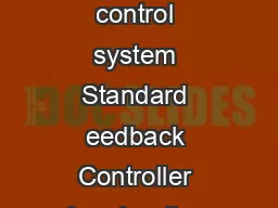
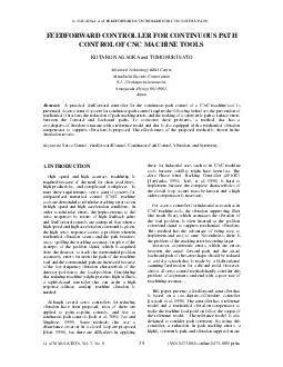
NAGAOKA et al FEEDFORWARD CONTROLLER FOR CONTINUOUS PATH IJ of SIMULATION Vol 7 No 8 ISSN 1473804x online 14738031 print 39 FEEDFORWARD CONTROLLER FOR CONTINUOUS PATH CONTROL OF CNC MACHINE TOOLS KOTARO NAGA ID: 23181

NAGAOKA FEEDFORWARD

Share:

Link:

Embed:

Download Presentation from below link

Download Pdf The PPT/PDF document "K NAGAOKA et al FEEDFORWARD CONTROLLER F..." is the property of its rightful owner. Permission is granted to download and print the materials on this web site for personal, non-commercial use only, and to display it on your personal computer provided you do not modify the materials and that you retain all copyright notices contained in the materials. By downloading content from our website, you accept the terms of this agreement.


Presentation Transcript

K. NAGAOKA et al: FEEDFORWARD CONTROLLER FOR CONTINUOUS PATH… I.J of SIMULATION, Vol. 7, No. 8 ISSN 1473-804x online, 1473-8031 print FEEDFORWARD CONTROLLER FOR CONTINUOUS PATH CONTROL OF CNC MACHINE TOOLS KOTARO NAGAOKA and TOMONORI SATO Advanced Technology R&D Center, Mitsubishi Electric Corporation 8-1-1 Tsukaguchi-honmachi, Amagasaki, Hyogo 661-8661, Japan K. NAGAOKA et al: FEEDFORWARD CONTROLLER FOR CONTINUOUS PATH… I.J of SIMULATION, Vol. 7, No. 8 ISSN 1473-804x online, 1473-8031 print Assuming the position command reaches to the vertex of the corner at , the coordinate value of the position command and is written as follows: ()cos ctvt ()sinctvtwhere is the velocity of the corner command along the path and is the exterior angle of the corner. Then, the coordinate value of the actual path p and p becomes ()cos()sin()(0)sin2(0)§·ªºt©¹¬¼ptvttvtttvtttwhere [()] H stands for the inverse Laplace transform of . Consequently, edge unsharpness is given by eyd . (3) (c) Asymmetric error Setting the time function () to the difference between the forward path and the backward path for the corner command along the y axis, it is said that ()()(2) yyydetptpttThus, the asymmetric error is given by max[()]. (4) DESIGN OF SERVO CONTROLLER Modeling of the Mechanical System In order to design a controller, a model of the mechanical system is required. There are, however, many vibration modes. In general, the most influential mode is the one that has the lowest eigenfrequency, because the vibration of a higher frequency is attenuated faster. A controller will then be designed to suppress the lowest mode of vibration and the model of the mechanical system is simplified to a two-mass system as shown in Fig. 3This model consists of the first mass (mass M ), the second mass (mass M ), a spring element (stiffness K ), and a damper element (viscous constant). The first mass receives force by an actuator such as a motor. The position of the first mass is detected as the detector position x to send to the controller as feedback. The position of the second mass represents the load position x which determines the actual path. The transfer function from the actuator force to the detector position is written as 222221aaarr s s and the one from the detector position to the load position is written as 2221aaaas where is the resonant frequency, is the anti- resonant frequency, is the resonant damping ratio, is the anti-resonant damping ratio, and M is the total mass, which is given by fa K M raC 12fazC M Actuatorforce Detector position Load position Mass 1 m f fC f K d x l x 1 M Mass 22 M Fig. 3 Model of mechanical system 3.2Structure of the Conventional Method The conventional controller for the servo control of a CNC machine tool is shown in Fig. 4. In this figure, x is the commanded position, x is the detector position, x is the load position, dis is the disturbance force, is the velocity loop compensator, is the position loop compensator, is the notch filter, and and are the coefficients that change the efficiency of the feedforward control. The notch filter removes those vibrations with frequencies that are resonant frequencies of the closed loop system and suppresses the vibration of the load position. Ordinarily, proportional (P) and proportional- integrate (PI) compensators are used as position and velocity loop compensators, respectively. Although there are various ways to design notch filters, a bi-quad filter is generally used [Dumetz et al, 2001; Ellis, 1991]. This filter is explained as follows: K. NAGAOKA et al: FEEDFORWARD CONTROLLER FOR CONTINUOUS PATH… I.J of SIMULATION, Vol. 7, No. 8 ISSN 1473-804x online, 1473-8031 print method. Each of the trajectory error parameters calculated in section 3.3 and section 3.5 are summarized in Table 1. The path of the corner shaped command for the conventional method and the proposed method is shown in Fig. 6 and Fig. 7respectively. The coordinate value of x axis and y axis are normalized by the values cos() and sin() , respectively. According to these table and figures, it is clear that the proposed method has a higher tracking ability and greater symmetry than the conventional method. Table 1 Comparison of trajectory error parameters Convention- al method Proposed method (B) Ratio (/) 0.25 0.056 sin(/2) 0.54 0.28 0.51 sin(/2) 0.15 0.0088   VXEQU   VXUK EQOOCPFGFRCVJCEVWCNRCVJ Fig. 6 Corner path in conventional method  VXEQU   VXUK EQOOCPFGFRCVJCEVWCNRCVJ Corner path in proposed method Case Study Numerical simulations are carried out to compare the two methods. However, while the mechanical model for designing the controller is a two-mass system, the actual mechanical system for the simulation is set as a three- mass system, in order to estimate the influence of modeling errors. The parameters of the actual mechanical system are shown in Table 2. In addition, the Bode diagram of the mechanical system is shown in Fig. 8The commanded path for the simulations is defined as follows: Corner shaped, a feedrate of 5mm/s, and a corner angle of /2 rad. In the conventional method, the frequency and the damping ratio of the notch filter is set to be the same as those of the first vibration mode, and the feedforward ratio and varies from 0.7 to 1.05, where . In the proposed method, the parameters of position, velocity, and force feedforward compensators are determined by the resonant frequency, the anti-resonant frequency, and the damping ratio of the first vibration mode of the mechanical system. The gain of the reference model varies from 30 rad/s to 55 rad/s. The simulations are executed using MATLAB/Simulink. Table 2 Parameters of mechanical system 1st mode 2nd mode Resonant frequency 200rad/s 400rad/s Anti-resonant frequency 150rad/s 300rad/s Damping /CIPKVWFG F$ 2JCUG FGI HTQOVQZHTQOVQZ (TG CFUGE Fig. 8 Bode diagram of mechanical system The relationship between vibration amplitude and edge unsharpness, which is obtained by the simulation, is shown in Fig. 9. In this paper, vibration amplitude is defined as the maximum amplitude of the actual path in the perpendicular direction of the commanded path after the K. NAGAOKA et al: FEEDFORWARD CONTROLLER FOR CONTINUOUS PATH… I.J of SIMULATION, Vol. 7, No. 8 ISSN 1473-804x online, 1473-8031 print Franklin G. F., Powell J. D., and Emami-Naeini A. 1994, Feedback Control of Dynamic Systems, 3rd ed. Reading, MA: Addison-Wesley. Hori Y. 1996, “A Review of Torsional Vibration Control Methods and a Proposal of Disturbance Observer- based New Techniques”. In Proceedings of 13 IFAC World Congress, Pp7-13. Itoh K., Iwasaki M., and Matsui N. 2004, “Optimal Design of Robust Vibration Suppression Controller Using Genetic Algorithms”. In IEEE Transactions on Industrial Electronics, vol. 51, no. 5, Pp947-953. Iwasaki T., Sato T., Morita A., and Maruyama H. 1996, “Auto-Tuning of Two-Degree-of-Freedom Motor Control for High-Accuracy Trajectory Motion”. In Control Engineering Practice, vol. 4, no. 4, Pp537-544. Koyama M. and Yano M. 1991, “Two Degrees of Freedom Speed Controller using Reference System Model for Motor Drives”. In Proceedings of 4European Conference on Power Electronics and Applications, Pp60-65. Pao L. Y. and Singhose W. E. 1995, “On the Equivalence of Minimum Time Input Shaping with Traditional Time-Optical Control”. In Proceedings of 4 IEEE Conference on Control ApplicationsPp1120-1125. Tomizuka M. 1994, “Zero Phase Error Tracking Algorithm for Digital Control”. ASME Journal of Dynamic Systems, Measurement, and Control109, no. 1, Pp583-592. Torfs D. E., Vuerinckx R., Swevers J., and Schoukens J. 1998, “Comparison of Two Feedforward Design Methods Aiming at Accurate Trajectory Tracking of the End Point of a Flexible Robot Arm”. In IEEE Transactions on Control Systems Technology, vol. 6, no. 1, Pp2-14. BIOGRAPHY Kotaro Nagaoka received his Master of Engineering degree from Kyoto University in 2001. He is currently a researcher in Advanced Technology R&D Center, Mitsubishi Electric Corporation and working on development of motion control systems for factory automation. Tomonori SATO received the B.E. and M.E in Engineering from Kyoto University, Japan, in 1990 and 1992 respectively. He joined the R&D Lab. in Mitsubishi Electric Co. in 1992. He received the Ph.D. degree in Engineering from Kyoto University, Japan in 2003. His research interests include motion control, machining process control and servo control for machine tool.