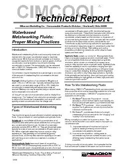
/
Most, but not all, metalworking systems have Most, but not all, metalworking systems have

Most, but not all, metalworking systems have - PDF document

natalia-silvester
natalia-silvester . @natalia-silvester
Follow
396 views
Uploaded On 2016-06-04

Most, but not all, metalworking systems have - PPT Presentation

OVERVIEW some form of ltration Whether it is a system for coolants cleaners stamping uids or corrosion preventives the intent is generally the same The purpose of ltration is to remove con ID: 348965

OVERVIEW some form ltration. Whether

Share:

Link:

Embed:

Download Presentation from below link

Download Pdf The PPT/PDF document "Most, but not all, metalworking systems ..." is the property of its rightful owner. Permission is granted to download and print the materials on this web site for personal, non-commercial use only, and to display it on your personal computer provided you do not modify the materials and that you retain all copyright notices contained in the materials. By downloading content from our website, you accept the terms of this agreement.


Presentation Transcript

OVERVIEW Most, but not all, metalworking systems have some form of ltration. Whether it is a system for coolants, cleaners, stamping uids or corrosion preventives, the intent is generally the same. The purpose of ltration is to remove contaminants in order to: » Help maintain the current uid in a status of “t for continued use. » Prolong the life of the uid by keeping it clean » Protect uid pumps from damage While there is both gravity and positive ltration, the vast majority of end users utilize positive ltration. Because of this aspect, this “Skill Builder” will focus on positive ltration. DEFINITION A lter is a porous, physical membrane/device with a function of separating contaminants (chips, nes, shop towels, cigarettes, dirt, etc.) from the main uid. The key to understanding the ltration is, “Just how clean does the uid have to be?” The answer to this question will dictate ltration type and conguration needed The effect of dirt and nes on the surface nish requirements of the nal part will generally dictate the lter system requirements. For example, if the operation is striving for a 10-micron nish, but the lter unit is permitting particles larger than that level, the nish requirements may not be met. Generally plant engineering and the lter manufacturer will decide on the overall design and set up of the ltration system. The designed system may ELEMENTS OF FILTRATION All lter systems have essentially the same elements in design. You need the following: » A process where the uid is used and becomes contaminated » A holding tank or reservoir that holds the bulk » A cleaning device where the ltration takes place; this could be part of the main holding tank or a separate tank » A “clean” tank that holds ltered uid; this could be a section/part of the main holding tank Filter systems tend to differ in their approach to handling the ow of the uid. There is: » Full ow - permits continuous cleaning of all the dirty uid » By-pass - only lters a small percentage of the dirty uid quakerchem.com | info@quakerchem.com © 2016 Quaker Chemical Corporation. All rights reserved. » Batch ltration - similar to the by-pass but handles a large volume as part of the ow Most operations with stringent nish requirements typically have that type of application set up on a by-pass lter. The by-pass lter would user ner ltration than the bulk operation. Setting up a series of FILTRATION successfully ner lters may be necessary to avoid blinding of the nal lter in the by-pass system. Usually it is the engineering staff that will dictate how much the nes will impact the nish. When references are made to the dirty side or clean side of the lter you have to understand where the uid is considered dirty (i.e. prior to ltration) or clean (i.e. after ltration). This understanding is important when using additives. Sometimes it is better to add to the dirty side versus the clean side depending upon the purpose of the additive. For systems where there is a clean side next to a dirty side, the clean side typically overows back into the dirty side as a way to maintain ow. METHODS OF FILTRATION Filtration can be conducted under gravity, vacuum or pressure. Gravity ltration is dependent upon the ow of the uid or the lack thereof. As the uid slows down, solids have a chance to settle to the bottom while lighter uids will rise to the surface. Many settling tanks have bafes or weirs that help to slow the speed of the uid. These same tanks also tend to have some form of drag bar/drag chain that sweeps across the bottom of the tank at scheduled intervals. The tank usually has an angled ramp at one end to permit the solids to be dragged up and out of the tank. Vacuum lters utilize a vacuum to pull uid through a membrane and leave the debris on the surface. Over time, a lter “cake” will build up providing ner and ner ltration. Usually, a vacuum lter is set to “index” when the vacuum reaches a specic level. Indexing is the process whereby the lter paper advances to yield more clean surface area for ltration or the drag chain moves across the surface of the lter to remove debris and yield more surface area for improved ltration. The level setting for the indexing is set by the manufacturer. This setting can be altered by the end user in order to use less media or improve the ltration. There are times when a certain contaminant might “blind” the media and cause the lter to index too often. A typical setting is 8-10 inches of mercury (in. Hg). A pressure lter is just the opposite of a vacuum lter. Pressure ltration tends to be more efcient because more volume can be forced through the media versus a vacuum set up. Because of this, pressure lters can have a smaller footprint but can also cost more money. Some systems can use a pre-coating to obtain ner ltration. The pre-coating can be something like diatomaceous earth (DE) or some form of ne cellulose. No matter what the pre-coat, the concept is to help build a thicker lter cake faster. A thicker cake means ner ltration. FILTRATION CAPACITY Filter media is rated as either nominal or absolute. These terms are used to describe the cut-off point at which lter membrane operates. Of course, these terms are applied under controlled laboratory conditions with FILTRATION low-pressure differentials. For example, a membrane rated at 10 microns nominal means that a high level percentage (~90%) of particles will not pass through at 10 microns. However, there can be a level of inconsistency in the lter media that permits larger particles to pass through. This also impacts absolute ratings. The term means this is the largest particle size that can pass through the membrane, under controlled conditions. There is a higher degree of consistency in a membrane with an absolute rating. Like the example above, a 10-micron absolute media means that a higher percentag�e (90%) of particles greater than 10 microns will not pass through. More media is being rated under absolute ratings instead of nominal ratings. FILTER PAPER (TYPES AND WEIGHTS) There are many manufacturers of lter paper but there is similarity in the materials themselves. Typical types of media are: » Polyester - generally good for coolants » Polyolens - both propylene and polyethylene are good for oil removal » Rayon » Nylon Other considerations for the type of media are high wet strength, lightweight, chemical resistance and cost. These are the details that the media supplier should provide. Certainly, their knowledge of their product will be critical in choosing the proper media. Beyond the parameters listed above, media performance is also chosen based on its weight (oz./yd 2 ), air permeability (ft. 3 /min.) and burst strength (PSI). There is not always a direct relationship between the weight and the porosity. It certainly makes sense that the more material per square yard that you have, should remove/retain more contaminants. See the table below for approximate comparisons. Again, the lter media supplier should be able to choose their best product for a given application. APPROXIMATE WEIGHT VS. POROSITY OUNCES/SQUARE YARD MICRON 2.25 - 3.0 10 0.90 - 1.00 50 0.60 - 0.80 100 0.50 - 0.70 150 0.40 - 0.60 200 0.40 - 0.50 300 STRIPPING OF FLUIDS The main concern, from a uid perspective, is to make sure that the ltration is not ner than the average particle size for the uid. The difference between an emulsion and a solution is important to understand. An emulsion is a mixture of “oil particles” (or whatever the primary lubricant is) evenly dispersed in water. The oil particle is not a hard particle, like a grain of sand, but is more like a porous water balloon. The “skin” of the balloon is the emulsier. If the skin gets broken, the particle falls apart. Remember, too, that particle sizes vary based on the level of emulsier. Soluble oils can range from 2-10 microns. FILTRATION Semi-synthetics are micro-emulsions and have an average particle size less than 1.0 microns. On the other hand, a solution does not have visible particles but still contains particles less than 0.1 microns. A solution will pass through lters that would strip a soluble oil or semi-synthetic. For example, if a product being used in an application has an average particle size of 5 microns, then the porosity of the lter media should be larger than 5 microns. The purpose of the lter is to remove the chips and other debris while allowing the emulsion to pass through unharmed or unaltered. The use of a 5-micron absolute lter would probably have a negative impact on the uid in this example! The “stripping” of an emulsion could result in poor performance and eventual emulsion instability. Key components can be stripped out of the uid. Ultra-ltration (UF) is sometimes used but it must be recognized that UF is extremely ne. UF uses a semi-permeable membrane, under pressure, to achieve a nominal cut-off of 95% or higher based on molecular weight. UF is unsuitable for soluble oils and semi-synthetics and can even strip out certain components of true solutions and cleaners. UF can lter as low as 0.05 microns! Many UF lters have pre- ltration, as low as 5 microns, to protect the UF membranes. Clogged UF membranes can be expensive to replace. Often times UF is used to process the nal waste stream from a waste treatment process. The UF will strip just about everything out of this process stage. TYPES OF FILTERS There are some standards used in the industry at this time. One manufacturer introduced the “wedge wire” concept for positive ltration years ago. Closely-knit wires run across the oor of the lter unit spaced about one ten thousandth of an inch apart. The wires are wedged-shaped so that the larger part of the wedge is at the surface and the narrower part faces toward the “clean side” of the lter. As the debris builds up on the surface of the wedge, the vacuum increases because it is more difcult to pull the uid through the debris. When the vacuum reaches its set point, the drag chain will move perpendicularly across the wires to remove the debris in order to create a renewed ltration surface. Another version of the wedge wire is called the suction indexing drum (SID). Imagine the wedge wire lter described above rolled into a large tube with both ends sealed. This tube is suspended in the dirty side. Suction is applied to one end of the tube so that uid and debris is pulled into the tube on all surfaces. Instead of having a drag chain that scrapes off the built up debris, the drum rotates against a xed blade that knocks the debris to the bottom of the tank. There, the drag chain scrapes the bottom of the tank and removes the debris. Also similar to the wedge wire is a porous metal plate, called a platen, covered with lter paper and supported by a vacuum chamber. The platen allows the lter paper to t tightly but not be pulled into the vacuum chamber. The method is employed with most paper lters. FILTRATION Bags, cartridges and canisters are replace - ments for paper. The concept remains the same except these media offer the option of serial ltration by altering the number and porosity of the ltering media. For example, there could be several lters in line with the rst lter at 25 microns, the second at 10 microns, and the last lter at 5 microns. This level of ltering actually works better than a single pass through a single porosity. The devices that contain these media are typically smaller and easier to work with versus a large pressure or vacuum lter. Much of this media is rated for specic applications based on ow rate and permeability. Another option to lter paper is a permabelt. A permabelt is used just like lter paper but is contained in a closed loop process. When the indexing process occurs, the permabelt moves ahead but passes through an area that back ushes the belt to remove the debris. Eventually the entire belt gets used over and over in ltering the uid. Permabelts are typically made of polypropylene. ADJUNCT PROCESSES It is possible to have other process equipment as part of keeping uid clean. These other processes are typically associated with removing additional nes or oating contamination, like tramp oil. Removing additional nes can be achieved via centrifugation, a hydrocyclone or magnetic separator. Commercial centrifuges have been used for years to remove nes as well as tramp oil and other oating contaminants. If properly maintained, a centrifuge will perform well in keeping the uid clean. It is possible, however, that some of the oil-soluble components can be extracted along with the tramp oil. The hydrocyclone uses a similar process as a centrifuge but has no moving parts. It tends to be less efcient and also relies on about 5-10% bypass of the uid to assist with removal of debris. Another method is a magnetic separator. The concept is the use of a magnetic conveyor that pulls metallic nes out of the uid and dumps them into a hopper. Of course, this only works for iron and steel alloys. Tramp oil removal can be achieved with an assortment of skimmers that pull the oating oil off of the surface. As mentioned above, a centrifuge will remove tramp oil. Also, coalescers are typically set up as part of a by-pass process. As the uid moves through the coalescer the ow rate decreases and provides the residual time to permit the coalescing to occur. TROUBLESHOOTING It would be expected that the supplier of the ltration system would provide the service to solve problems. However, there are many times that the response is too slow or the uid gets blamed without investigation. Below are some suggestions based on Quaker’s experiences. If the question arises as to whether the lter is working or not, the rst action to take is to obtain samples from the clean side and dirty side. You can also compare the clean side to a sample coming out of the nozzle at the machine that is using the uid. FILTRATION Sometimes fairly simple tests can be conducted to compare the uid samples. In some cases, it might be necessary to run a particle size analysis. If the question above indicates that ltration is not occurring, then the supplier must get involved. It is possible that one of the following is part of the problem: » The SID is not rotating properly. There could be something physical blocking the gear mechanism that impacts the drum rotation or something is jammed against the scraper blade » The scraper blade that cleans the SID is bent or is somehow not contacting the surface. The scraper blade should be changed every 12 months » The lter paper is torn or continues to tear because of some blockage as the paper is loaded into the ltration area » For systems that utilize bag or cartridge lters conrm that the bag/cartridge is the correct model and is properly tted in place » Make sure that the vacuum setting was set properly and is currently at that setting. Sometimes adjustments are made to overcome a temporary problem and the original setting is not re-established. The same can happen with timed settings » Many systems are set up with some type of by-pass mechanism that guarantees that the clean side can never starve the demand. This mechanism permits the dirty side to ow into the clean side. Make sure that this mechanism is functioning properly » Make sure nozzles are not clogged and they are properly aimed at the work area to provide maximum coverage with the uid A SID can be lifted out of the system for inspection. Unfortunately, systems with ltration at the bottom of the tank can only be inspected by draining the entire system. This applies to standard wedge wire systems as well as vacuum lters that utilize paper ltration. This obviously can have a large impact on getting any work performed on the system if there is nowhere to store the current uid. CONCLUSION Understanding how the uid system functions can be critical to successful operations. You can provide input to your customer to help them solve their problems. This makes you more valuable to them as a supplier. FILTRATION quakerchem.com | info@quakerchem.com © 2016 Quaker Chemical Corporation. All rights reserved. quakerchem.com | info@quakerchem.com © 2016 Quaker Chemical Corporation. All rights reserved. 03.16-V003 A LOCAL PARTNER YOU CAN DEPEND ON. ANYWHERE IN THE WORLD. Our Associates are on the ground in every region of the globe. That means our entire infrastructure (from sales to service, R&D to manufacturing) is designed to support our customers at a local level, whether in one facility or spread across multiple plants worldwide. Put the right partner to work for you during every step of success. Contact Quaker today to transform your business from the inside.