/
www.vishay.com www.vishay.com

www.vishay.com - PDF document

natalia-silvester
natalia-silvester . @natalia-silvester
Follow
391 views
Uploaded On 2016-08-11

www.vishay.com - PPT Presentation

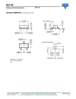
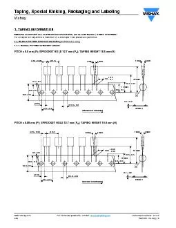
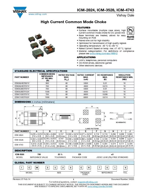
Document Number 40076For technical questions contact polytechvishaycom THIS DOCUMENT IS SUBJECT TO CHANGE WITHOUT NOTICE THE PRODUCTS DESCRIBED HEREIN AND THIS DOCUMENTARE SUBJECT TO SPECIFIC DI ID: 442360

Document Number: 40076For technical questions

Share:

Link:

Embed:

Download Presentation from below link

Download Pdf The PPT/PDF document "www.vishay.com" is the property of its rightful owner. Permission is granted to download and print the materials on this web site for personal, non-commercial use only, and to display it on your personal computer provided you do not modify the materials and that you retain all copyright notices contained in the materials. By downloading content from our website, you accept the terms of this agreement.


Presentation Transcript

www.vishay.com Document Number: 40076For technical questions, contact: polytech@vishay.com THIS DOCUMENT IS SUBJECT TO CHANGE WITHOUT NOTICE. THE PRODUCTS DESCRIBED HEREIN AND THIS DOCUMENTARE SUBJECT TO SPECIFIC DISCLAIMERS, SET FORTH AT www.vishay.com/doc?91000 INTRODUCTIONTantalum electrolytic capacitors are the preferred choice inapplications where volumetric efficiency, stable electrical parameters, high reliability, and long service life are primaryconsiderations. The stability and resistance to elevatedtemperatures of the tantalum/tantalum oxide/manganesedioxide system make solid tantalum capacitors anappropriate choice for today's surface mount assemblyVishay Sprague has been a pioneer and leader in this field,producing a large variety of tantalum capacitor types forconsumer, industrial, automotive, military, and aerospaceelectronic applications.Tantalum is not found in its pure state. Rather, it iscommonly found in a number of oxide minerals, often incombination with Columbium ore. This combination isknown as tantaliteŽ when its contents are more thanone-half tantalum. Important sources of tantalite includeAustralia, Brazil, Canada, China, and several Africancountries. Synthetic tantalite concentrates produced fromtin slags in Thailand, Malaysia, and Brazil are also asignificant raw material for tantalum production.Electronic applications, and particularly capacitors,consume the largest share of world tantalum production.Other important applications for tantalum include cuttingtools (tantalum carbide), high temperature super alloys,chemical processing equipment, medical implants, andmilitary ordnance.Vishay Sprague is a major user of tantalum materials in theform of powder and wire for capacitor elements and rod andsheet for high temperature vacuum processing.THE BASICS OF TANTALUM CAPACITORSMost metals form crystalline oxides which arenon-protecting, such as rust on iron or black oxide oncopper. A few metals form dense, stable, tightly adhering,electrically insulating oxides. These are the so-calledvalveŽmetals and include titanium, zirconium, niobium,tantalum, hafnium, and aluminum. Only a few of thesepermit the accurate control of oxide thickness byelectrochemical means. Of these, the most valuable for theelectronics industry are aluminum and tantalum.Capacitors are basic to all kinds of electrical equipment,from radios and television sets to missile controls andautomobile ignitions. Their function is to store an electrical charge for later use.Capacitors consist of two conducting surfaces, usuallymetal plates, whose function is to conduct electricity. Theyare separated by an insulating material or dielectric. Thedielectric used in all tantalum electrolytic capacitors istantalum pentoxide.Tantalum pentoxide compound possesses high-dielectricstrength and a high-dielectric constant. As capacitors arebeing manufactured, a film of tantalum pentoxto their electrodes by means of an electrolytic process. Thefilm is applied in various thicknesses and at various voltagesand although transparent to begin with, it takes on differentcolors as light refracts through it. This coloring occurs on thetantalum electrodes of all types of tantalum capacitors.Rating for rating, tantalum capacitors tend to have as muchas three times better capacitance/volume efficiency thanaluminum electrolytic capacitors. An approximation of thecapacitance/volume efficiency of other types of capacitorsmay be inferred from the following table, which shows thedielectric constant ranges of the various materials used ineach type. Note that tantalum pentoxide has a dielectricconstant of 26, some three times greater than that ofaluminum oxide. This, in addition to the fact that extremelythin films can be deposited during the electrolytic processmentioned earlier, makes the tantalum capacitor extremelyefficient with respect to the number of microfarads availableper unit volume. The capacitance of any capacitor isdetermined by the surface area of the two conductingplates, the distance between the plates, and the dielectricconstant of the insulating material between the plates.In the tantalum electrolytic capacitor, the distance betweenthe plates is very small since it is only the thickness of thetantalum pentoxide film. As the dielectric constant of thetantalum pentoxide is high, the capacitance of a tantalumcapacitor is high if the area of the plates is large:whereC = capacitancee = dielectric constantA = surface area of the dielectrict = thickness of the dielectricTantalum capacitors contain either liquid or solidelectrolytes. In solid electrolyte capacitors, a dry material (manganese dioxide) forms the cathode plate. A tantalumlead is embedded in or welded to the pellet, which is in turnconnected to a termination or lead wire. The drawings showthe construction details of the surface mount types oftantalum capacitors shown in this catalog. COMPARISON OF CAPACITORDIELECTRIC CONSTANTSDIELECTRICDIELECTRIC CONSTANT Air or vacuum1.0 Paper2.0 to 6.0 Plastic2.1 to 6.0 Mineral oil2.2 to 2.3 Silicone oil2.7 to 2.8 Quartz3.8 to 4.4 Glass4.8 to 8.0 Porcelain5.1 to 5.9 Mica5.4 to 8.7 Aluminum oxide8.4 Tantalum pentoxide26 Ceramic12 to 400K C= www.vishay.com Document Number: 40076For technical questions, contact: polytech@vishay.com THIS DOCUMENT IS SUBJECT TO CHANGE WITHOUT NOTICE. THE PRODUCTS DESCRIBED HEREIN AND THIS DOCUMENTARE SUBJECT TO SPECIFIC DISCLAIMERS, SET FORTH AT www.vishay.com/doc?91000 SOLID ELECTROLYTE POLYMER TANTALUM CAPACITORSSolid electrolyte polymer capacitors utilize sintered tantalum pellets as anodes. Tantalum pentoxide dielectric layer is formedon the entire surface of anode, which is further impregnated with highly conductive polymer as cathode system.The conductive polymer layer is then coated with graphite, followed by a layer of metallic silver, which provides a conductivesurface between the capacitor element and the outer termination (lead frame or other).Molded chip polymer tantalum capacitor encases the element in plastic resins, such as epoxy materials. After assembly, thecapacitors are tested and inspected to assure long life and reliability. It offers excellent reliability and high stability for variety ofapplications in electronic devices. Usage of conductive polymer cathode system provides very low equivalent series resistance(ESR), which makes the capacitors particularly suitable for high frequency applications. TANTALUM CAPACITOR WITH POLYMER CATHODE TYPE T50 / T55 / T56 TANTALUM CAPACITOR WITH POLYMER CATHODE TYPE T58 Silver adhesive Solderable cathode termination Polymer / carbon / silver coating Sintered tantalum pellet Epoxy encapsulation Lead frame welded to Ta wire Anode polarity bar Solderable anode termination Anode polarity bar Side anode termination (+) Side cathode termination (-)EncapsulationSintered tantalum pelletPolymer / carbon / silver coating Glass reinforced epoxy resin substrateBottom cathode termination (-)Silver adhesive epoxyConductive stripRating / markingBottom anode termination (+)Copper padAnode wire www.vishay.com Document Number: 40076For technical questions, contact: polytech@vishay.com THIS DOCUMENT IS SUBJECT TO CHANGE WITHOUT NOTICE. THE PRODUCTS DESCRIBED HEREIN AND THIS DOCUMENTARE SUBJECT TO SPECIFIC DISCLAIMERS, SET FORTH AT www.vishay.com/doc?91000 TANTALUM CAPACITOR WITH POLYMER CATHODE TYPE T52 TANTALUM CAPACITOR WITH POLYMER CATHODE TYPE T54 / T59 Polarity barSide anode termination (+)Side cathode termination (-)Bottom anodeSilver plated copper substrateBottom cathodeSilver adhesive epoxyConductive stripT52 E5 caseEncapsulationPolymer / carbon / silver coating Sinteredtantalum pellet T52 M1 caseSide anode termination (+)Bottom anode termination (+)Polarity bar markingSide cathode termination (-)Sinteredtantalum pelletPolymer / carbon / silver coating Silver platedcopper strateBottom cathode termination (-)Silver adhesive epoxy Encapsulation Anode polarity markingSide anode termination (+)Side cathode termination (-)EncapsulationSintered tantalum pelletPolymer / carbon / silver coatingTop / bottom cathode termination (-)Silver plated copper substrateTop / bottom cathode termination (-)Top / bottom anode termination (+)Top / bottom anode termination (+)Conductive stripSilver adhesive epoxy www.vishay.com Document Number: 40076For technical questions, contact: polytech@vishay.com THIS DOCUMENT IS SUBJECT TO CHANGE WITHOUT NOTICE. THE PRODUCTS DESCRIBED HEREIN AND THIS DOCUMENTARE SUBJECT TO SPECIFIC DISCLAIMERS, SET FORTH AT www.vishay.com/doc?91000 POLYMER CAPACITORS - MOLDED CASESERIEST50, T55, T56PRODUCT IMAGEVPolyTanperformance polymerFEATURESHigh performanceTEMPERATURE RANGE-55 °C to +105 °CCAPACITANCE RANGE3.3 F to 1000 F2.5 V to 63 VCAPACITANCE TOLERANCELEAKAGE CURRENT0.1 CVDISSIPATION FACTORESRCASE SIZESJ, P, A, T, B, Z, V, D, CTERMINATION FINISHCases J, P, C: 100 % tinCase A, T, B, Z, V, D: Ni / Pd / Au POLYMER CAPACITORS - LEADFRAMELESS MOLDED CASESERIEST52T58T59T54PRODUCTIMAGEvPolyTansurface mount chip capacitors, low profile, leadframeless molded typevPolyTan polymer surface mount chip capacitors, compact, leadframeless molded typevPolyTan polymer surface mount chip capacitors,low ESR, leadframelessmolded typevPolyTansurface mount chip capacitors, low ESR, leadframeless molded type, hi-rel commercial off-the-shelf (COTS)FEATURESLow profileSmall case sizeMultianodeHi-rel COTS, multianodeTEMPERATURE-55 °C to +105 °C-55 °C to +105 °C-55 °C to +105 °C-55 °C to +125 °CCAPACITANCERANGE 47 µF to 1500 µF1 µF to 330 µF15 µF to 470 µF15 µF to 470 µF10 V to 35 V6.3 V to 35 V16 V to 75 V16 V to 75 VCAPACITANCETOLERANCE± 20 %± 20 %± 10 %, ± 20 %± 20 %LEAKAGECURRENT0.1 CVDISSIPATION10 %8 % to 14 %10 %10 %ESR to 150 mCASE SIZESE5, M1, M9, B2MM, M0, W0, W9,A0, AA, B0, BBEEEETERMINATION100 % tin100 % tin / lead www.vishay.com Document Number: 40076For technical questions, contact: polytech@vishay.com THIS DOCUMENT IS SUBJECT TO CHANGE WITHOUT NOTICE. THE PRODUCTS DESCRIBED HEREIN AND THIS DOCUMENTARE SUBJECT TO SPECIFIC DISCLAIMERS, SET FORTH AT www.vishay.com/doc?91000 MOLDED CAPACITORS, T50 / T55 / T56 TYPESNote€A reel diameter of Note€A reel diameter of PLASTIC TAPE AND REEL PACKAGING DIMENSIONSTAPE WIDTH812A + 0 / - 3Ø 180B + 1 / 0Ø 60C ± 0.2Ø 13D ± 0.5Ø 21E ± 0.52.0W ± 0.39.013.0 PLASTIC TAPE SIZE DIMENSIONSCASE CODEA ± 0.2B ± 0.2W ± 0.3F ± 0.1E ± 0.1P ± 0.1tmax.J1.01.88.03.51.754.01.3P1.42.28.03.51.754.01.6A1.93.58.03.51.754.02.5T3.13.88.03.51.754.01.7B3.13.88.03.51.754.02.5C3.76.312.05.51.758.03.1Z4.87.712.05.51.758.02.6V4.87.712.05.51.758.02.6D4.87.712.05.51.758.03.4 DEWBAC Direction of tape flowInserting directiontAFP1WBEØ 1.5Pocket+ 0.104.0 ± 0.12.0 ± 0.1 PerforationSymbol: R Marking side (upper)Mounting terminal side (lower) www.vishay.com Document Number: 40076For technical questions, contact: polytech@vishay.com THIS DOCUMENT IS SUBJECT TO CHANGE WITHOUT NOTICE. THE PRODUCTS DESCRIBED HEREIN AND THIS DOCUMENTARE SUBJECT TO SPECIFIC DISCLAIMERS, SET FORTH AT www.vishay.com/doc?91000 LEADFRAMELESS MOLDED CAPACITORS, ALL TYPESNotes€Metric dimensions will govern. Dimensions in inches are rounded and for reference only, are determined by the maximum dimensions to the ends of the terminals extending from the component body and / or the bodydimensions of the component. The clearance between the ends of the terminals or body of the component to the sides and depth of thecavity (A) must be within 0.002" (0.05 mm) minimum and 0.020" (0.50 mm) maximum. The wed must also prevent the cavity of not more than 20°Tape with components shall pass around radius RŽ without damage. The minimum trailer length may length to provideRŽ minimum for 12 mm embossed tape for reels with hub diameters approaching N minimumThis dimension is the flat area from the edge of the sprocket hole to either outward deformation of the carrier tape between the embossedthe cavity whichever is lessThis dimension is the flat area from the edge of the carrier tape opposite the sprocket holes to either the outward deformation of the carrierity or to the edge of the cavity whichever is lessThe embossed hole location shall be measured from the sprocket hole controlling the location of the embossment. Dimensions ofembossment location shall be aof each otherrence dimension tape feeder clearance only PLASTIC TAPE AND REEL PACKAGING in inches [millimeters]Tape and Reel Specifications: all case sizes areStandard reel diameter is 7" [178 mm]. max.K0Tape thickness Embossment0.069 ± 0.004[1.75 ± 0.10]D1 (min.) for components 0.079 x 0.047 [2.0 x 1.2] and larger rotation(Side or front sectional view) reference onlyConcentric around BTopTop cover cavity size Cathode (-)Anode (+)DIRECTION OF FEED component rotationTypicalTypical(Top view) Tapeape0.039 [1.0]max.0.039 [1.0]max.CamberAllowable camber to be 0.039/3.937 [1/100](Top view) www.vishay.com Document Number: 40076For technical questions, contact: polytech@vishay.com THIS DOCUMENT IS SUBJECT TO CHANGE WITHOUT NOTICE. THE PRODUCTS DESCRIBED HEREIN AND THIS DOCUMENTARE SUBJECT TO SPECIFIC DISCLAIMERS, SET FORTH AT www.vishay.com/doc?91000 NotesFor reference onlyis with paper tape. Plastic tape is available per requestNote are determined by the maximum dimensions to the ends of the terminals extending from the component body and / or the bodydimensions of the component. The clearance between the ends of the terminals or body of the component to the sides and depth of thecavity (A) must be within 0.002" (0.05 mm) minimum and 0.020" (0.50 mm) maximum. The clearance allowed must also prevent rotationvity of not more than 20° CARRIER TAPE DIMENSIONS in inches [millimeters]CASE CODETAPE SIZEB (MAX.) (1) (MIN.)FK (MAX.)PE512 mm0.329 [8.35]0.059 [1.5]0.217 ± 0.002[5.50 ± 0.05]0.071 [1.8]]0.476 ± 0.008[12.1 ± 0.20]8 mm0.075 [1.91]0.02 [0.5]0.138 [3.5]0.043 [1.10]0.157 [4.0]0.315 [8.0]M1, M912 mm0.32 [8.2]0.059 [1.5]0.217 ± 0.002[5.5 ± 0.05]0.094 [2.39]9]0.472 + 0.012 / - 0.004472 + 0.012 / - 0.004W98 mm0.126 [3.20]0.030 [0.75]0.138 [3.5]0.045 [1.15]0.157 [4.0]0.315 [8.0]W08 mm0.126 [3.20]0.030 [0.75]0.138 [3.5]0.045 [1.15]0.157 [4.0]0.315 [8.0]A08 mm-0.02 [0.5]0.138 [3.5]0.049 [1.25]0.157 [4.0]0.315 [8.0]AA8 mm0.154 [3.90]0.039 [1.0]0.138 [3.5]0.079 [2.00]0.157 [4.0]0.315 [8.0]B012 mm0.181 [4.61]0.059 [1.5]0.217 [5.5]0.049 [1.25]0.157 [4.0]0.315 [8.0]BB8 mm0.157 [4.0]0.039 [1.0]0.138 [3.5]0.087 [2.22]0.157 [4.0]0.315 [8.0]EE12 mm0.32 [8.2]0.059 [1.5]0.217 ± 0.002[5.5 ± 0.05]0.175 [4.44][8.0 ±1.0]0.472 + 0.012 / - 0.004472 + 0.012 / - 0.004B28 mm0.157 [4.0] 0.039 [1.0]0.138 [3.5] 0.057 [1.45]0.157 [4.0]0.315 [8.0] PAPER TAPE AND REEL PACKAGING DIMENSIONS in inches [millimeters]CASEEFWTMM8 mm0.041 ± 0.002[1.05 ± 0.05]0.071 ± 0.002[1.8 ± 0.05]0.06 ± 0.004[1.5 ± 0.1]0.157 ± 0.004[4.0 ± 0.1]0.157 ± 0.004[4.0 ± 0.1]0.079 ± 0.002[2.0 ± 0.05]0.069 ± 0.004[1.75 ± 0.1]0.0138 ± 0.002[3.5 ± 0.05]0.315 ± 0.008[8.0 ± 0.2]0.037 ± 0.002[0.95 ± 0.05]M08 mm0.049 ± 0.002[1.25 ± 0.05]0.081 ± 0.002[2.05 ± 0.05]0.06 ± 0.004[1.5 ± 0.1]0.157 ± 0.004[4.0 ± 0.1]0.157 ± 0.004[4.0 ± 0.1]0.079 ± 0.002[2.0 ± 0.05]0.069 ± 0.004[1.75 ± 0.1]0.0138 ± 0.002[3.5 ± 0.05]0.315 ± 0.008[8.0 ± 0.2]0.041 ± 0.002[1.05 ± 0.05] Ø D0 T Bottom cover P1A0 B0E2P2 W P0 E1 Cavity ize Bottom cover tape USER FEED DIRECTION Cavity center line cover tape[10 pitche cumulative tolerance on tape ± 0.2 mm] G Anode www.vishay.com Document Number: 40076For technical questions, contact: polytech@vishay.com THIS DOCUMENT IS SUBJECT TO CHANGE WITHOUT NOTICE. THE PRODUCTS DESCRIBED HEREIN AND THIS DOCUMENTARE SUBJECT TO SPECIFIC DISCLAIMERS, SET FORTH AT www.vishay.com/doc?91000 PACKING AND STORAGEPolymer capacitors meet moisture sensitivity level rating (MSL) of 3 or 4 as specified in IPC/JEDEC J-STD-020 and are drypackaged in moisture barrier bags (MBB) per J-STD-033. MSL for each particular family is defined in the datasheet - either inFeaturesŽ section or Standard RatingsŽ table. Level 3 specifies a floor life (out of bag) of 168 hours and level 4 specifies life of 72 hours at 30 °C maximum and 60 % relative humidity (RH). Unused capacitors should be re-sealed in the MBB withfresh desiccant. A moisture strip (humidity indicator card) is included in the bag to assure dryness. To remove excess moisturecapacitors can be dried at 40 °C (standard dry boxŽ conditions).For detailed recommendations please refer to J-STD-033.Notes€T50, T52, T55, T56, and T58 capacitors are process sensitive.PSL classification to JEDEC J-STD-075: R4G€T54 and T59 capacitors with 100 % tiprocess sensitive.PSL classification to JEDEC J-STD-075: R6G RECOMMENDED REFLOW PROFILESthan 3 cycles of reflow in accordance with J-STD-020.PROFILE FEATURESnPb EUTECTIC ASSEMBLYLEAD (Pb)-FREE ASSEMBLYPREHEAT AND SOAKTemperature min. (TSmin.)100 °C150 °CTemperature max. (TSmax.)150 °C200 °CTime (t) from (TSmax.) 60 s to 120 s60 s to 120 sRamp-up rate (T)3 °C/s maximum)183 °C217 °CTime (t) maintained above T60 s to 150 sPeak package body temperature (T) max.Depends on type and case - see table belowTime (t) within 5 °C of the peak max. temperature20 s5 sRamp-down rate (T)6 °C/s maximumTime from 25 °C to peak temperature6 min maximum8 min maximum PEAK PACKAGE BODY TEMPERATURE (TTYPECASE CODEPEAK PACKAGE BODY TEMPERATURE (T) MAX.SnPb EUTECTIC ASSEMBLYLEAD (Pb)-FREE ASSEMBLYT55J, P, A, T, B, C, Z, V, DT52E5, M1, M9, B2260 °CT58MM, M0, W9, W0, A0, AA, B0, BB260 °CT50DT56DT59EE220 °C250 °CT54EE220 °C250 °C Time TemperaturetS Time 25 °C to peak tpTPTLTSmin.25 tL TSmax. Preheat area Max. ramp up rate = 3 °C/s www.vishay.com Document Number: 40076For technical questions, contact: polytech@vishay.com THIS DOCUMENT IS SUBJECT TO CHANGE WITHOUT NOTICE. THE PRODUCTS DESCRIBED HEREIN AND THIS DOCUMENTARE SUBJECT TO SPECIFIC DISCLAIMERS, SET FORTH AT www.vishay.com/doc?91000 MOLDED CAPACITORS, T50 / T55 / T56 TYPESLEADFRAMELESS MOLDED CAPACITORS, ALL TYPES PAD DIMENSIONSDIMENSIONSCAPACITOR SIZEPAD DIMENSIONSLWG (max.)Z (min.)X (min.)Y (Ref.)J1.60.80.72.51.00.9P2.01.250.52.61.21.05A3.21.61.13.81.51.35T / B3.52.81.44.12.71.35C5.83.22.96.92.72.0Z / V / D7.34.34.18.22.92.05 PAD DIMENSIONS in inches [millimeters]FAMILYCASE CODEA (NOM.)B (MIN.)C (NOM.)D (MIN.)E50.094 [2.40]0.073 [1.85]0.187 [4.75]0.333 [8.45]M1, M90.161 [4.10]0.073 [1.85]0.187 [4.75]0.333 [8.45]B20.094 [2.39]0.044 [1.11]0.072 [1.82]0.159 [4.03]MM, M00.024 [0.61]0.027 [0.70]0.025 [0.64]0.080 [2.03]W0, W90.035 [0.89]0.029 [0.74]0.041 [1.05]0.099 [2.52]AA, A0, A20.047 [1.19]0.042 [1.06]0.065 [1.65]0.148 [3.76]BB, B00.094 [2.39]0.044 [1.11]0.072 [1.82]0.159 [4.03]T59 / T54EE0.209 [5.30]0.098 [2.50]0.169 [4.30]0.366 [9.30] CapacitorPatternLYZG BCD www.vishay.com Document Number: 40076For technical questions, contact: polytech@vishay.com THIS DOCUMENT IS SUBJECT TO CHANGE WITHOUT NOTICE. THE PRODUCTS DESCRIBED HEREIN AND THIS DOCUMENTARE SUBJECT TO SPECIFIC DISCLAIMERS, SET FORTH AT www.vishay.com/doc?91000 GUIDE TO APPLICATIONAC Ripple Current: the maximum allowable ripplecurrent shall be determined from the formula:where,P = power dissipation in W at +45 °C as given inthe tables in the product datasheets. = the capacitor equivalent series resistance atthe specified frequency.AC Ripple Voltage: the maximum allowable ripplevoltage shall be determined from the formula:or, from the formula:where,P = power dissipation in W at +45 °C as given inthe tables in the product datasheets. = The capacitor equivalent series resistance atthe specified frequency.Z = The capacitor impedance at the specifiedfrequency.2.1The tantalum capacitors must be used in such acondition that the sum of the working voltage andripple voltage peak values does not exceed the ratedvoltage as shown in figure below. power dissipation isaffected by the heat sinking capability of themounting surface. If these capacitors are tobe operated at temperatures above +45 °C, thepermissible ripple current (or voltage) shall becalculated using the derating coefficient as shown in the capacitors are not intended foruse with reverse voltage applied. However, they arecapable of withstanding momentary reverse voltagepeaks, which must not exceed the following values:At 25 °C: 10 % of the rated voltage or 1 V, whicheverAt 85 °C: 5 % of the rated voltage or 0.5 V, whicheverAt 105 °C: 3 % of the rated voltage or 0.3 V,whichever is smaller. capacitors can be attached byconventional soldering techniques; vapor phase,convection reflow, infrared reflow, wave soldering,and hot plate methods. The soldering profile chartsshow recommended time / temperature conditionsfor soldering. Preheating is recommended. Therecommended maximum ramp rate is 2 °C per s.Attachment with a soldering iron is notrecommended due to the difficulty of controllingtemperature and time at iron must never come in contact with the capacitor.For details see www.vishay.com/doc?40214 Limit Pressure on Capacitor Installation withMounter: pressure must not exceed 4.9 N with a tool end diameter of 1.5 mm when applied to thecapacitors using an absorber, centering tweezers, orsimilar (maximum permitted pressurization time: 5 s).An excessively low absorber setting position wouldresult in not only the application of undue force to thecapacitors but capacitor and other componentscattering, circuit board wiring breakage, and / orcracking as well, particularly when the capacitors aremounted together with other chips having a height of1 mm or less.Flux Selection5.3.1Select a flux that contains a minimum of chlorine andamine.5.3.2After flux use, the chlorine and amine in the fluxremain must be removed. the following solvents areusable when cleaning the capacitors after mounting.Never use a highly active solvent.€Halogen organic solvent (HCFC225, etc.)€Alcoholic solvent (IPA, ethanol, etc.)€Petroleum solvent, alkali saponifying agent, water,etc.Circuit board cleaning must be conducted at atemperature of not higher than 50 °C and for animmersion time of not longer than 30 minutes. Whenan ultrasonic cleaning method is used, cleaning mustbe conducted at a frequency of 48 kHz or lower, atan vibrator output of 0.02 W/cm, at a temperature ofnot higher than 40 °C, and for a time of 5 minutes orNotes€Care must be exercised in cleaning process so that themounted capacitor will not come into contact with anycleaned object or the like or will not get rubbed by a stiffbrush or similar. If such precautions are not takenparticularly when the ultrasonic cleaning method isemployed, terminal breakage may occur€When performing ultrasonic cleaning under conditionsother than stated above, conduct adequate advancecheckoutMAXIMUM RIPPLE CURRENT TEMPERATURE DERATING FACTOR 45 °C1.055 °C0.885 °C0.6105 °C0.4125 °C0.25 RMSESR------------ RMS------------ RMS VoltageRipple voltageOperatingvoltageWorking voltageTime (s)