/
INSTRUCTION MANUAL & PARTS LISTING INSTRUCTION MANUAL & PARTS LISTING

INSTRUCTION MANUAL & PARTS LISTING - PDF document

olivia-moreira
olivia-moreira . @olivia-moreira
Follow
405 views
Uploaded On 2016-08-08

INSTRUCTION MANUAL & PARTS LISTING - PPT Presentation

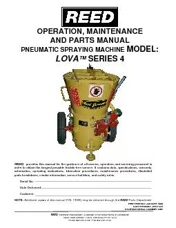
001759 SEPT 08 TABLE OF CONTENTS Safety Warnings 11 Airless Spray gun Assembly Airless Spray Gun Troubleshooting Rev Tips Field Troubleshooting Servicing Outlet Valve Servicing Inlet Valve Gearbox As ID: 438083

001-759 SEPT 08 TABLE CONTENTS Safety

Share:

Link:

Embed:

Download Presentation from below link

Download Pdf The PPT/PDF document "INSTRUCTION MANUAL & PARTS LISTING" is the property of its rightful owner. Permission is granted to download and print the materials on this web site for personal, non-commercial use only, and to display it on your personal computer provided you do not modify the materials and that you retain all copyright notices contained in the materials. By downloading content from our website, you accept the terms of this agreement.


Presentation Transcript

001-759 SEPT 08 INSTRUCTION MANUAL & PARTS LISTING TABLE OF CONTENTS Safety Warnings 11 Airless Spray gun Assembly Airless Spray Gun Troubleshooting Rev Tips Field Troubleshooting Servicing Outlet Valve Servicing Inlet Valve Gearbox Assembly Clutch Assembly Frame Assembly Swivel Wheel Assembly Gun Assembly Gun Holder Assembly Suction Assembly Optional Floating Gun Assembly Clutch Troubleshooting Striping Accessories 30 1 Filling the Packing Nut/Wet Cup 2. Spray Tip 3. Prime Valve 5. Choke, Fuel Throttle 11 11 9. Spray Tip 11 10. Spray Tip Assembly 11 11. Airless Spray Gun Assembly 13. Outlet Valve 14. Inlet Valve 17. Gearbox Assembly 18. Clutch Assy 19. Frame Assembly 20. Swivel Wheel Assembly 21. Gun Assembly 22. Gun Holder Assembly 24. Suction Assembly 25. Optional Floating Gun Assembly NO MODIFICATIONS or alterations of any PIONEER Equipment or part is allowed. All Service Procedures to be performed by an Authorized Service Center ONLY HANDLE THIS UNIT AS YOU WOULD A LOADED FIREARM! HIGH PRESSURE SPRAY CAN CAUSE EXTREMELY SERIOUS INJURY. OBSERVE ALL WARNINGS! MANUAL NOTATIONS WARNING - Alerts user to avoid or correct conditions that could cause bodily injury. CAUTION - Alerts user to avoid or correct conditions that could cause damage to or destruction of equipment. IMPORTANT - Alerts users to steps or procedures that are essential to proper equipment repair and maintenance. NOTE - Identi�es essential procedures or extra information. BEFORE OPERATING THIS UNIT, READ AND FOLLOW ALL SAFETY WARNINGS AND INSTRUCTIONS RELATED TO THE USAGE OF THIS EQUIPMENT ON PAGES 2, 3 & 4. READ, LEARN, AND FOLLOW THE PRESSURE RELIEF PROCEDURE ON PAGE 9 OF THIS MANUAL. Model BS 3000 Max Pressure 3000 PSI (206 BAR) Output (At Pressure) 0.80 GPM (3 Liters/min) Standard Spray Tip 217 (4” wide stripe, .0.017” Ori�ce) Max Spray Tip 1 gun @ 0.029 in. 1”x8” (30cm) Line The heart of the BS 3000 is our time tested and contractor proven piston paint pump. Designed for spraying 2500 gallons per year, this pump is used daily by thousands of painting professionals worldwide--with a reputation for trouble free performance that’s unmatched in the industry. It’s compact, easy to use, and quick to clean. Even changing colors is a breeze. Stripe with water-based paints made for athletic �elds or traf�c lines. A professional quality spray gun is mounted on a multi-position spray arm. Great balance and light weight make it ideal for a one-man operation. A quick release of the spray gun from its mount lets you paint using stencils, or utilize the 50' of supplied hose and the spray gun to paint with exterior latex and enamel paints. Flexibility makes the BS3000 popular with professional athletic facilities, major college programs, cities, school districts, and sports programs. Use it for athletic �elds or parking lot striping, and for use as a mobile airless spraying station. It’s perfect for painting fences, buildings, and covering graf�ti. NOTE TO PHYSICIAN: Injection in the skin is a traumatic injury. It is important to treat the injury surgically as soon as possible. DO NOT DELAY treatment to research toxicity. Tox icity is a concern with some exotic coatings injected directly into the blood stream. Consultation with a plastic surgeon or reconstructive hand surgeon may be advisable. FLUIDS UNDER HIGH PRESSURE FROM SPRAY OR LEAKS CAN PENETRATE THE SKIN AND CAUSE EXTREMELY SERIOUS INJURY, INCLUDING THE NEED FOR AMPUTATION. NEVER point the spray gun towards anyone or at any part of the body. NEVER put hand or �ngers over the spray tip. Do not use rag or other materials over your �ngers. Paint will penetrate through material and into the hand. NEVER try to stop or de�ect leaks with your hand or body. ALWAYS have gun tip guard in place when spraying. ALWAYS lock gun trigger when you stop spraying. ALWAYS remove tip from the gun to clean it. NEVER try to "blow back" paint, it’s not an air sprayer. ALWAYS follow the PRESSURE RELIEF PROCEDURE, as shown on page 9, before cleaning or removing the spray tip or servicing any system equipment. Be sure equipment safety devices are operating properly before each use. ALWAYS tighten all �uid connections before each use. If any �uid appears to penetrate your skin, get EMERGENCY CARE AT ONCE. DO NOT TREAT AS A SIMPLE CUT. • Go to an emergency room immediately. • Tell the doctor you suspect an injection injury. • Tell him what kind of material you were spraying with and have him read NOTE TO PHYSICIAN above. NEVER alter equipment in any manner. NEVER smoke while in spraying area. NEVER spray highly �ammable materials. NEVER use around children. NEVER allow another person to use sprayer unless he is thoroughly instructed on its' safe use and given this operators manual to read. ALWAYS wear a spray mask, gloves and protective eye wear while spraying. ALWAYS ensure �re extinquishing equipment is readily available and properly maintained. NEVER LEAVE SPRAYER UNATTENDED WITH PRESSURE IN THE SYSTEM. FOLLOW PRESSURE RELIEF PROCEDURES ON PAGE 9. Keep spraying area free from obstructions. Make sure area has good ventilation to safely remove vapors. NEVER keep �ammable material in spraying area. NEVER spray in vicinity of open �ame or other sources of ignition. Spraying area must be at least 20 ft. away from spray unit. HIGH PRESSURE SPRAY CAN CAUSE EXTREMELY SERIOUS INJURY. OBSERVE ALL WARNINGS. THIS SPRAYER IS FOR PROFESSIONAL USE ONLY. ALWAYS set safety lock on the gun in " LOCKED " position when not in use and before servicing or cleaning. DO NOT remove or modify any part of gun. ALWAYS remove spray tip when cleaning. Flush unit with LOWEST POSSIBLE PRESSURE. CHECK operation of all gun safety devices before each use. Be very careful when removing the spray tip or hose from gun. A plugged line contains �uid under pressure. If the tip or line is plugged, follow the PRESSURE RELIEF PROCEDURE as outlined on page 9. TIP GUARD ALWAYS have the tip guard in place on the spray gun while spraying. The tip guard alerts you to the injection hazard and helps prevent accidentally placing your �ngers or any part of your body close to the spray tip. USE EXTREME CAUTION when cleaning or changing spray tips. If the spray tip clogs while spraying, engage the gun safety latch immediately. ALWAYS follow the PRESSURE RELIEF PROCEDURE before removing the spray tip to clean it. NEVER wipe off build up around the spray tip. ALWAYS remove tip & tip guard to clean AFTER pump is turned off and the pressure is relieved by following the PRESSURE RELIEF PROCEDURE. ALWAYS INSPECT SPRAYING AREA WARNINGS CONTINUED ON NEXT PAGE......... WARNINGS MEDICAL ALERT - Airless Spray Wounds If any �uid appears to penetrate your skin, get EMERGENCY MEDICAL CARE AT ONCE. DO NOT TREAT AS A SIMPLE CUT. Tell the doctor exactly what �uid was injected. Have him read the following "NOTE TO PHYSICIAN". GENERAL PRECAUTION MEDICAL TREATMENT SPRAY TIP SAFETY TIP GUARD SPRAY GUN SAFETY WARNINGS - CONTINUED Hazardous �uid or toxic fumes can cause serious injury or death if splashed in eyes or on skin, inhaled or swallowed. Know the hazards of the �uid you are using. Store & dispose of hazardous �uids according to manufacturer, local, state & national guidelines. ALWAYS wear protective eyewear, gloves, clothing and respirator as recommended by �uid manufacturer. Keep all labels on the unit clean and readable. Replacement labels are available from manufacturer. Tighten all �uid connections securely before each use. High pressure �uid can dislodge a loose coupling or allow high pressure spray to be emitted from the coupling and result in an injection injury or serious bodily injury. Use only hose that has a spring guard. The spring guard helps protect the hose from kinks or other damage which could result in hose rupture and cause an injection injury. NEVER use a damaged hose, which can result in hose failure or rupture and cause in injection injury or other serious bodily injury or bodily damage. Before each use, check entire hose for cuts, leaks, abrasion or bulging of cover, or damage or movement of couplings. If any of these conditions exist, replace the hose immediately. Never use tape or any device to try to mend the hose as it cannot contain the high pressure �uid. NEVER ATTEMPT TO RECOUPLE THE HOSE. High pressure hose is not recoupleable. Help prevent damage to the hose by handling and routing it carefully. Do not move the sprayer by pulling it with the hose. Ground the sprayer and other components in the system to reduce the risk of static sparking, �re or explosion which can result in serious bodily injury and property damage. ALWAYS GROUND ALL OF THESE COMPONENTS: 1. Sprayer: Connect a ground wire and clamp (supplied) to a true earth ground. 2. Fluid Hose: use only grounded hoses. 3. Spray gun or dispensing valve: grounding is obtained through connection to a properly grounded �uid hose and pump. 4. Object being sprayed: according to your local code. 5. All solvent pails used when �ushing should only be metal pails which are conductive. Once each week, check electrical resistance of hose (when using multiple hose assemblies, check overall resistance of unpressurized hose must not exceed 29 megohms (max) for any coupled length or combination of hose lengths. If hose exceeds these limits, replace it immediately. Never exceed 500 Ft. (150 m.) overall combined hose length to assure electrical continuity. Keep clear of moving parts when starting or operating the sprayer. Do not put your �ngers into any openings to avoid amputation by moving parts or burns on hot parts.Precaution is the best insurance against an accident. When starting the engine, maintain a safe distance from moving parts of the equipment. Before adjusting or servicing any mechanical part of the sprayer, follow the PRESSURE RELIEF PROCEDURE on page 9, and remove the ignition cable from the spark plug to prevent accidental starting of sprayer. TOXIC FLUID HAZARD WARNINGS CONTINUED ON NEXT PAGE......... ALWAYS INSPECT SPRAYING AREA BEFORE PERFORMING ADJUSTMENTS OR REPAIRS Disconnect spark plug wire and keep it away from spark plug. Disconnect battery at negative terminal (only engines with electric start). WHEN TESTING FOR SPARK Use approved spark plug tester. Do not check for spark with spark plug removed. WARNING: Clean spilled paint off the top of the gauge glass before it dries in order to read gauge. This sprayer operates at 3000 psi (205 bar). ALWAYS be sure that all components and accessories have a maximum working pressure of at least 3000 psi to avoid rupture which can result in serious bodily injury including injection and property damage. NEVER leave a pressurized sprayer unattended to avoid accidental operation of it which could result in serious bodily injury. ALWAYS follow the PRESSURE RELIEF PROCEDURE whenever you stop spraying and before adjusting, removing or repairing any part of the sprayer. NEVER alter or modify any part of the equipment to avoid possible component rupture which could result in serious bodily injury and property damage. NEVER use weak or damaged or non-conductive paint hose. Do not allow kinking or crushing of hoses or allow it to vibrate against rough or sharp or hot surfaces. Before each use, check hoses for damage and wear and ensure all �uid connections are secure. REPLACE any damaged hose. NEVER use tape or any device to mend the hose. NEVER attempt to stop any leakage in the line or �ttings with your hand or any part of the body. Turn off the unit and release pressure by following PRESSURE RELIEF PROCEDURE. ALWAYS use approved high pressure �ttings and replacement parts. ALWAYS ensure �re extinquishing equipment is readily available and properly maintained. Place unit 25 feet away from spraying in ventilated area. NEVER operate in buildings unless exhaust is piped outside. NEVER allow hose to lay against engine muf�ers or hot parts. NEVER re�ll fuel tank while engine is hot or is running. IMPORTANT: United States Government safety standards have been adopted under the Occupational Safety & Health Act. These standards, particularly the General Standards, Part 1910, & the Construction Standards, part 1926 should be consulted. WHEN SPRAYING & CLEANING WITH FLAMMABLE PAINTS OR THINNERS: 1. When spraying with �ammable liquids, the unit must be located a minimum of 25 feet away from the spraying area in a well ventilated area. Ventilation must be suf�cient enough to prevent the accumulation of vapors. 2. To eliminate electrostatic discharge, ground the spray unit, paint bucket and spraying object. Use only high pressure airless hoses approved for 3000 psi which is conductive. 3. Remove spray tip before cleaning gun and hose. Make contact of gun with bucket and spray without the tip in a well ventilated area, into the grounded steel bucket. 4. Never use high pressure in the cleaning process. USE MINIMUM PRESSURE. 5. Do not smoke in spraying/cleaning area. Reduce the risk of injection injury, static sparking or splashing by following the speci�c cleaning procedure on page 6 and 9. ALWAYS follow the PRESSURE RELIEF PROCEDURE on page 9. ALWAYS remove the spray tip before �ushing. Hold a metal part of the gun �rmly to the side of a metal pail and use the lowest possible �uid pressure during �ushing. NEVER use cleaning solvents with �ash points below 140 degress F. Some of these are: acetone, benzene, ether, gasoline, naphtha. Consult your supplier to be sure. NEVER SMOKE IN THE SPRAYING/CLEANING AREA. ALWAYS be sure all equipment and objects being sprayed are properly grounded. ALWAYS ground sprayer, paint bucket and object being sprayed. See "grounding" on page 3 for detailed grounding information. Vapors created when spraying can be ignited by sparks. To reduce the risk of �re, always locate the sprayer at least 20 feet (6 m.) away from the spray area. DO NOT plug in or unplug any electrical cords in the spray area, which can create sparks, when there is any chance of igniting vapors still in the air. Follow the coating & solvent manufacturers safety warnings and precautions. Use only conductive �uid hoses for airless applications. Be sure gun is grounded through hose connections. Check ground continuity in hose & equipment. Overall (end to end) resistance of unpressurized hose must not exceed 29 megohms for any coupled length or combination of hose length. Use only high pressure airless hoses with static wire approved for 3000 psi. WARNING Do not use halogenated solvents in this system. The prime valve, 2 gun manifold and most airless guns have aluminum parts and may explode. Cleaning agents, coatings, paints or adhesives may contain halogenated hydrocarbon solvents. DON"T TAKE CHANCES! Consult your material suppliers to be sure. Some of the most common of these solvents are: Carbontetrachloride, Chlorobenzene, Dichloroethane, Dichlo roethyl Ether, Ethylbromide, Ethylchloride, Tethrachloethane. Alternate valves and guns are available if you need to use these solvents. AVOID COMPONENT RUPTURE PREVENT STATIC SPARKED FIRE/ EXPLOSIONS WARNINGS - CONTINUED FIG. 1 1. CONNECT THE HOSE AND GUN 2. FILL THE PACKING NUT/WET CUP 3. CHECK THE ENGINE OIL LEVEL 4. FILL THE FUEL TANK a. Remove the plastic cap plug from the outlet and screw a conductive or grounded 3000 psi spray hose onto �uid outlet. b. Connect an airless spray gun to the other end of the hose, but do not install the spray tip yet! NOTE: Do not use thread sealer on swivel unions as they are made to self seal. NOTE: The 6' whip hose should always be 3/8". Fill the Packing Nut/Wet Cup 1/3 full with Throat Seal Oil (TSO) (pn# 2501). FIG 1 BELOW. a. Unscrew the oil �ll plug. The dipstick is attached to the plug. b. Without threading the plug into place, check to be sure the oil is up to the top mark on the dipstick. c. If oil is needed, refer to engine manual. WARNING: Fuel spilled on a hot surface can cause a �re or explosion and cause serious bodily injury and property dam age. Always shut off the engine and let it cool before �lling the tank, and carefully follow steps a - c below being sure not to spill any fuel. a. Close the fuel shutoff valve. b. Use only clean, fresh, well-known brands of unleaded regular grade gasoline. c. Remove the fuel cap and �ll tank. Be sure the air vent in the �ll cap is not plugged so fuel can �ow to the carburetor, then replace the cap. Your unit was factory tested in an anti-freeze solution which was left in the pump. Before using oil-base paint, �ush with mineral spirits only. Before using water-base paint �ush with mineral spirits, followed by soapy water, then a clean water �ush. Flush with a compatible solvent such as mineral spirits or water. Flush with soapy water, then mineral spirits. Flush with mineral spirits, followed by soapy water, then a clean water �ush. 3. CHANGING FROM WATER-BASE TO OIL-BASE PAINT 4. CHANGING FROM OIL-BASE TO WATER-BASE PAINT Oil-base paint: Flush with mineral spirits. Water-base paint: Flush with water, then mineral spirits and leave the pump, hose and gun �lled with mineral spirits. For longer storage, use mixture of mineral spirits and motor oil (half & half). Shut off the sprayer, follow PRESSURE RELIEF PROCEDURE on page 9 to relieve pressure and make sure prime valve is left open. Before using water-base paint, �ush with soapy water and then a clean water �ush. When using oil-base paint, �ush out the mineral spirits with the material to be sprayed. 1. NEW SPRAYER 5. STORAGE 6. START UP AFTER STORAGE 5. FLUSH THE SPRAYER a. Flush sprayer per instructions below. USING THE “QUICK FLUSH” FOR DAILY CLEAN-UP PAINT MUST BE FLUSHED FROM THE STRIPER WITH WATER AFTER EACH USE. THE “QUICK FLUSH” ADAPTER SIMPLIFIES THIS OPERATION. IT ALLOWS YOU TO RECOVER THE PAINT IN THE HOSE AND SPRAY GUN, AND SAVES YOU TIME. STEP 4: Attach a garden hose to the Quick Flush System; lock your gun open by putting the �at washer on the chain between the gun body and the retainer, then turn on your water supply to full pressure. STEP 1: Follow the Pressure Relief Procedure and lift the suction assembly out of the paint container. Cycle pump slowly and allow it to empty paint out of the suction assembly and the �uid pump. STEP 2: Turn machine off, place suction assembly into a clean empty bucket & close the prime pressure valve. STEP 3: Remove tip and guard from gun & clean the individual pieces. Attach Quick Flush System to the gun. STEP 6: Once water appears in the paint, close the prime pressure valve and place the return hose back into the empty bucket with the suction hose. STEP 7: Open prime pressure valve & use the water �owing through the return hose to spray clean the suction hose & inlet strainer as you �ll the bucket. STEP 8: Turn on and cycle the pump slowly to �ush the suction assembly and the �uid pump. STEP 9: When bucket is half full, stop the pump, close the prime valve & clean outside of the suction assembly by hand. Remove suction assembly from bucket & dispose of the contaminated water per the paint manufacturer’s instruction. Place suction assembly back into the clean empty bucket and open the prime pressure valve. STEP 10: Turn off the machine and follow the Pressure Relief Procedure. Check the �lters in the gun handle, the high- pressure �lter (if equipped) and the inlet strainer to make sure they are clean. Reattach the tip and tip guard to the gun. The pump is now clean and ready for storage. STEP 11: Once pump is clean, add Pump Conditioner (1 oz. per gallon) to water in the bucket, turn off the water supply & remove the Quick Flush System from the gun. Place gun in bucket with the Pump Conditioner, shut your prime pressure valve & operate the gun using low pressure to �ush the Pump Conditioner through gun and hose. STEP 5: Hold return hose in the paint container and open the prime pressure valve. Paint in the hose and gun will now be forced back through the bypass hose into your paint bucket for future use. BE SURE TO RELIEVE PRESSURE IN THE PUMP AFTER FILLING WITH AIRLESSCO PUMP CONDITIONER. AIRLESSCO AIRLESS SPRAY GUN AIRLESS PAINT HOSE FLAT WASHER RING WARNING : To reduce the risk of static sparking, which can cause �re or explosion, always hold a metal part of the gun �rmly against the metal pail when �ushing. This also reduces splashing. Refer to Fig 6. 1. Be sure the gun safety latch is engaged and there is no spray tip in the gun. Refer to Fig. 2. Refer to your separate instruction manual provided with your gun on its safety features and how to engage safety latch. 2. Pour enough clean, compatible solvent into a large, empty metal pail to �ll the pump and hoses. 3. Place the suction tube into the pail or place the pail under the pump. 4. Turn pressure control knob to low. Refer to Fig. 4. 5. Open the prime valve to the open - "Priming Position". This will allow an easy start. Refer to Fig. 3. 6. Turn the engine ON/OFF switch to ON. 7. Move the choke toward the closed position as per Fig.5. 8. Move the throttle lever slightly to the left as per Fig.5. 9. Turn the fuel valve ON as per Fig. 5. Pull the start rope. Pull the engine over against compression stroke and then let the rope rewind slowly into the starter. Pull �rmly and rapidly to start the engine. Do NOT drop the rope. Hold on to the handle while rewinding, or the rope may rewind improperly and jam the assembly. If the engine does not start, open the choke a little more. If the engine �oods, open the choke all the way and continue cranking. 10. After the engine is warm, gradually close the choke, raise the RPM of engine slightly by moving throttle to the left. Close the prime valve. Refer to Fig. 3 11. Point the gun into the metal pail and hold a metal part of the gun �rmly against the pail Refer to �g. 6. 12. Disengage the gun safety latch and squeeze the gun trigger. At the same time, slowly turn the pressure control knob clockwise just enough to move liquid at low pressure. 13. Allow the pump to operate until clean solvent comes from the gun. 14. Release the trigger and engage the gun safety latch. 15. If you are going to start spraying, place the pump or suction tube into the supply container. Release the gun safety latch and trigger the gun into another empty, metal container, holding a metal part of the gun �rmly against the metal pail (Fig. 6), forcing the solvent from the pump and hose. When paint starts coming from gun, turn pressure control knob to minimum pressure, place prime valve in prime (open) position and engage the gun safety latch. 16. If you are going to store the sprayer, remove the suction tube or pump from the solvent pail force the solvent from the pump and hose. Engage the gun safety latch and refer to the "Storage" Procedure on page 5. Step 5. 17. Whenever you shut off the sprayer follow the PRESSURE RELIEF PROCEDURE warning on page 9. HOW TO FLUSH REMOVE SPRAY TIP. ENGAGE GUN SAFETY LATCH. FIG. 2 CHOKE LEVER FUEL VALVE THROTTLE LEVER FIG. 5 PRIME VALVE CLOSED (Pressure) OPEN (Priming & Pressure Relief FIG. 3 FIG. 4 PRESSURE CONTROL KNOB HIGH PRESSURE MAINTAIN FIRM METAL TO METAL CONTACT BE TWEEN GUN AND CONTAINER FIG. 6 STARTING UP a. Turn the Pressure Control Knob Clockwise to increase pressure and counterclockwise to decrease pressure. b. Always use the lowest pressure necessary to completely atomize the material. NOTE: OPERATING THE SPRAYER AT HIGHER PRESSURE THAN NEEDED, WASTES MATERIAL, CAUSES EARLY TIP WEAR, AND SHORTENS SPRAYER LIFE. PRESSURE CONTROL KNOB is used to adjust pressure. Turn clockwise (CW) to increase pressure and counterclockwise (CCW) to decrease pressure. PRIME/PRESSURE (PR) RELIEF VALVE is used to prime pump and to relieve pressure from gun, hose and tip. 2. PREPARE THE MATERIAL a. Prepare the material according to the material manufacturer's recommendations. b. Place the suction tube into the material container. 3. STARTING THE SPRAYER Prime/PR Valve must be "OPEN" in the priming position. b. When you have ensured that the gun safety latch is engaged, attach tip and safety guard. c. Turn the engine ON/OFF switch to the "ON" position. Pull rope vigorously until engine starts. d. Turn Pressure Control Knob clockwise to prime the pump. e. After the pump is primed, turn Prime/PR Valve to the "Closed" position. f. Turn Pressure Control Knob to the desired spray pressure. g. Disengage the gun safety latch and you are ready to spray. 4. ADJUSTING THE PRESSURE FOLLOW THE "PRESSURE RELIEF PROCEDURE". To reduce the risk of injection, never hold your hand, body, �ngers or hand in a rag in front of the spray tip when cleaning or checking for a cleared tip. Always point the gun toward the ground or into a waste container when checking to see if the tip is cleared or when using a self-cleaning tip. When you spray into the paint bucket, always use the lowest spray pressure and maintain �rm metal to metal contact between gun and container. To stop the unit in an emergency, turn the engine off. Then relieve the �uid pressure in the pump and hose as instructed in the Pressure Relief Procedure. a. Whenever you stop spraying, even for a short break, follow the "Pressure Relief Procedure". b. Clean the tip & gun as recommended in the seperate Gun Manual supplied with the gun. c. Flush the sprayer at the end of each work day, if the material you are spraying is water-based, or if it could harden in the sprayer overnight. See "Flushing". Use a compatible solvent to �ush, then �ll the pump and hoses with an oil based solvent such as mineral spirits. d. For long term shutdown or storage, refer to the "Flushing" section of this manual. 5. WHEN SHUTTING OFF THE SPRAYER Be sure to relieve pressure in the pump after �lling with Airlessco Pump Conditioner. AVOIDING TIP CLOGS There is an easy way to keep the outside of the tip clean from material build up: Every time you stop spraying, for even a minute, lock the gun and submerge it into a small bucket of thinner suitable for the material sprayed. Thinner will dissolve the buildup of paint on the outside of tip, tip guard and gun much more effectively if the paint doesn't have time to dry out completely. (Prime/PR Valve) Used to relieve pressure from gun, hose & tip and to primethe unit when in OPEN position. (It is in open positionwhen there is a wider gap between valve handle and cam body.) When in CLOSED position,there is only a very slight gap between handle & body. When closed the system is pressurized. Handle as a loaded �rearm! c. If more coverage is needed, use a larger tip rather than increasing the pressure. d. Check the spray pattern. The tip size and angle determines the pattern width and �ow rate. 5. Re-engage gun safety latch and close Prime/Pressure Relief Valve. TO AVOID POSSIBLE SERIOUS BODY INJURY, ALWAYS FOLLOW THIS PROCEDURE WHENEVER THE SPRAYER IS SHUT OFF, WHEN CHECKING IT, WHEN INSTALLING, CHANGING OR CLEANING TIPS, WHENEVER YOU STOP SPRAYING, OR WHEN YOU ARE INSTRUCTED TO RELIEVE THE PRESSURE. IMPORTANT! 1. Engage the gun safety latch. Refer to the separate instruction manual provided with your gun on its safety features and how to engage safety latch. 2. Turn the unit off. 3. Disengage the gun safety latch and trigger the gun to relieve residual �uid pressure. HOLD METAL PART OF THE GUN IN CONTACT WITH GROUNDED METAL PAIL. USE MINIMUM PRESSURE ! 4. Turn Prime/Pressure Relief Valve (PR Valve) to the open (priming) position to relieve residual �uid pressure. THERE WILL BE A WIDER GAP BETWEEN VALVE HANDLE AND CAM BODY WHEN IN OPEN POSITION. IN THE CLOSED POSITION THERE IS ONLY A VERY SLIGHT GAP. NOTE: THE VALVE HANDLE CAN MOVE BOTH CLOCKWISE AND COUNTER CLOCKWISE AND CAN FACE DIFFERENT DIRECTIONS. If the SPRAY TIP OR HOSE IS CLOGGED , follow Step 1 through 5 above. Expect paint splashing into the bucket while relieving pressure during Step 4. If you suspect that pressure hasn't been relieved due to damaged Prime/Pressure Relief Valve or other reason, engage the gun safety latch and take your unit to an authorized Airlessco Service Center. 1. Always stop the pump at the bottom of its stroke when you take a break or at the end of the day. This helps keep material from drying on the rod, damaging the packings. 2. Keep the displacement pump packing nut/wet cup 1/3 full of Throat Seal Oil (2501) at all times. The TSO helps protect the packings and rod. 3. Lubricate Connecting Rod Pin every 3 months. 4. Inspect the packing nut daily. Your paint pump has a patented "Triple Life Packing System". Packing life will be extended a minimum of 3 times if the proper packing tightening procedure is followed! DAILY MAINTENANCE PACKING TIGHTENING PROCEDURE: Inspect the packing nut daily! If seepage of paint into the packing nut and/ or movement of the piston upward is found (while not spraying), the packing nut should be tightened enough to stop leakage only, but not any tighter. OVERTIGHTENING WILL DAMAGE THE PACKINGS and reduce the packing life to the life of other piston pumps. a. Stripers are factory aligned, but if necessary, loosen the two bolts (�g. 20, item 19) on the swivel wheel assembly, just enough to be able to move the wheel by hand. Align wheel and re-tighten bolts. b. Place the turnbuckle over the two mounting nubs on the frame. c. Pressurize the unit with water and Airlessco's Pump Conditioner and spray out several lines with the swivel assembly in the locked position. Use the turnbuckle to �ne tune the alignment of the wheels, until the stripes are straight. d. Tighten the jam nuts on the turnbuckle to af�x the turnbuckle length for future reference. e. Tighten the ratchet handles. CURVES AND ARCS Basically the same as above, except the swivel wheel assembly is set at angle. The swivel assembly can be adjusted to 30 degrees either side of straight ahead. If you have arcs that you paint regularly, purchase additional turnbuckles (136-231) and keep them set to those arc sizes. LINE STRIPING OPERATION There is a hole in each corner of the striper frame, in which the gun arm can be mounted. In a standard set up, the gun arm would be mounted in the right hand near the single wheel. This allows for an easier visual check for straight line striping and for basic arc striping. a. Ensure that a striping tip is in the gun. b. Pick a tip size for the desired line width. EXAMPLE : a 317ST tip for a four inch line. c. Place gun into the gun holder, so that the top of the taper on the gun handle is �ush with the edge of the gun holder. d. Set gun height for the desired line width. Adjust height by loosening the small black handle on the gun holder assembly and slide the gun arm to the correct height. Now tighten the handle. This will require some experimentation to �nd the correct height. It is suggested that tape, or some other method is used to mark the height of commonly used settings. e. Attach the swivel heads to the gun if painting curbs or wide stripes. f. Angle the guns slightly forward. This allows the spray pressure from the guns to help blow dirt and debris out of the path of the new stripes. Once the handle and gun arm assembly is set up to the preferred position, pressurize the unit and trigger the gun to ensure that it activates and releases correctly. If not, adjust the cable tension as follows: a. Locate the adjustment knobs on the base of the gun trigger, where the cable connects to the gun trigger assembly. b. Loose the locking nut and move the adjusting screw until the slack has been removed from the cable. c. Tighten locking nut and retest gun triggers for proper function. NOTE: THERE IS AN ADDITIONAL CABLE ADJUSTMENT WHERE THE CABLE ATTACHES TO THE GUN HOLDER ASSEMBLY. USE ONLY IF THE GUN TRIGGER ADJUSTMENT IS INSUFFICIENT. CURBS: Adjust gun to desired height and turn swivel head towards curb. b. WIDE STRIPES: Install wider fan striping tips and raise the gun height to achieve the desired width line. c. STENCILS: Install standard spray tip on the outer gun. Remove this gun from the gun holder and spray out the stencils. A second gun and hose can be attatched and bolted with a ball valve for stencils. d. STANDARD PAINTING: Same as stencils, but use additional paint hose as required. 4. CABLE TENSION ADJUSTMENT 6. MISCELLANEOUS OPPERATIONS 3. SETTING UP THE GUNS 1. CHOOSE THE GUN ARM POSITION 5. ALIGN SWIVEL WHEEL ASSEMBLY Choose the handlebar position. The handlebars can be adjusted by loosening the bolts (�g. 19, item 10) and rotating each handlebar to desired heights, then tightening the bolts. Rotating the handlebars all the way forward allows for easy storage of the unit. RELEASING THE SWIVEL WHEEL SWIVEL WHEEL SETTING THE SWIVEL WHEEL ANGLE SPRAY Attach spray gun to airless unit and tighten �ttings securely. Set the gun safety latch. (Also may be called gun safety lock, or trigger lock) * The gun safety latch should always be set when the gun is not being triggered. Read all warnings and safety precautions supplied with the spray gun and in product manual. MAJOR COMPONENTS OF SPRAY GUN AND REVERSIBLE SPRAY TIP FIG. 7 1. Be sure pressure relief procedure is followed before assembling tip and housing to the gun. 2. Lock gun safety latch. 3. Insert REV-TIP™ cylinder into the REV-GUARD™ (guard housing assembly). 4. Guide metal seat into REV-GUARD™ (guard housing assembly) through retaining nut & turn until it seats against the cylinder. 5. Insert O-Ring gasket on metal seat so it �ts in the grooves. 6. Finger tighten REV-GUARD™ retaining nut onto the gun. 7. Turn guard in the desired position. 8. Completely tighten the retaining nut. 1. Lock gun safety latch. 2. Turn REV-TIP™ handle 180 degrees. 3. Disengage trigger lock & trigger gun into pail. 4. If the REV-TIP™ handle appears locked (resists turning), loosen the retaining nut. The handle will now turn easily. 5. Engage gun safety latch & return handle to the spray position. Spray Position Shown REVERSE TO UNPLUG RETAINING NUT CLOGGED FLAT TIP Should the spray tip become clogged, relieve pressure from hose by following the "Pressure Relief Procedure." Secure gun with the safety latch, take off guard, take out the tip, soak in appropriate solvent & clean with a brush. (Do not use a needle or sharp pointed instrument to clean the tip. The tungsten carbide is brittle and can chip.) CLEANING SPRAY GUN Immediately after the work is �nished, �ush the gun out with a solvent. Brush pins with solvent and oil them lightly so they will not collect dried paint. To clean the �lter, use a brush dipped in an appropriate solvent. Change or clean �lters at least once a day. Some types of latex may require a �lter change after four hours of operation. SPRAY TIP ASSEMBLY CLEANING FILTER IN GUN HANDLE TO REMOVE CLOGS FROM SPRAY TIP FIG. 10 METAL SEAT REV-TIP™ CYLINDER RETAINING NUT REV-GUARD™ GUARD HOUSING ASSEMBLY G Thread 7/8" 561-002 F Thread 11/16" 561-001 REVERSIBLE SPRAY TIP TIP GUARD (FILTER INSIDE) GUN SAFETY LATCH OR LOCK FIG. 8 FIG. 9 METAL SEAT REV-GUARD™ REV-TIP™ AIRLESS SPRAY GUN OPERATION GUN SAFETY LATCH GUN SAFETY LATCH 11 AIRLESS SPRAY GUN FIG. 11 PARTS LIST FIGURE 11 Item No. Part No. Description 1* 120-530 Gun Seat Assembly 2* 120-535 Gasket-Seat 3* 120-520 Needle Assembly 120-529 Gun Seat Adapter 120-562 Trigger Guard 120-539 Pivot Trigger Pin 120-509 Gun Head 120-540 Actuator Pin (2) 120-536 Gun Plate 10* 120-038 Nut 11 120-056 Plastic Washer 12 120-538 Gun Trigger Lock 13 120-055 Wave Washer 14 120-049 Retaining Ring 15 120-082 Handle Seal 16 2590 Gun Filter-Coarse 2590F Gun Filter-Fine 17 2591 Spring 18 2613 Gun Handle Assembly 19 120-506 Gun Trigger 2521 Gun Repair Kit AIRLESS SPRAY TROUBLESHOOTING Coarse spray Low pressure Increase the pressure Excessive fogging (overspray) High pressure Material too thin Reduce the pressure to satisfactory pattern distrabution Use less thinner Patten too wide Spray angle too large Use smaller spray angle tip Pattern too narrow Spray angle too small use larger spray angle tip ( if coverage is OK, try tip in same nozzle group) Too much material Nozzle too large Material too thin Pressure too high Use smaller nozzle Reduce pressure Too little material Nozzle too small Use next larger nozzle Material too thick Thin distribution in center of pattern “horns” Worn tip Wrong tip Change to new tip Use nozzle with narrow spray angle Thick skin on work Material too viscous Application too heavy Thin cautiously Reduce pressure and/or use tip in next smaller nozzle group Coating fails to close & smooth over Material too viscous Thin cautiously Spray pattern irregular, de�ected Ori�ce clogged Tip damaged Clean carefully Replace with new tip Craters or pock marks, bubbles on work Solvent balance Use 1 to 3% “short solvents remainder “long” solvents (this is most likely to happen with material of low viscosity, lacquers, etc.) Clogged screens Extraneous material in paint Course pigments Poorly milled pigments (paint pigments glocculate) Clean screen Use coarse screen if ori�ce size allows. Use courser screen, larger ori�ce tips. Obtain ball milled paint. If thinner has been added, test to see if a cover screen. Incompatible drop placed on top of paint mixes or �attens out on the paint mixture & thinners on the surface. If not, try different thinner in fresh batch of paint. GOOD, FULL SPOTTY PATTERN, INCREASE PRESSURE TEST THE PATTERN LINE STRIPING TIP CHART REV-TIP TM FAN WIDTH (6” FROM SURFACE) 1-2 25-51 2597 2600 2-4 51-102 2601 2594 2598 2599 4-6 102-152 2595 2604 2605 Striping paint Oil Base Oil Base Latex Latex Latex Unit doesn’t prime Airleak due to: • loose suction nut • worn o-rings • hole in sucktion hose Stuck or fouled balls • tighten suction nut • replace o-ring (2589) on suction seat & o-ring (2584) below suction seat • replace suction hose (2529) • service outlet valve suction assembly Unit primes but has poor or no pressure Pressure set too low Filter(s) are clogged Outlet valve fouled/worn Prime/pressure relief valve bypassing Packings and/or piston worn • turn up pressure • clean or replace gun �lter, inlet �lter, and/or manifold �lter • service outlet valve • clean or replace prime valve • tighten packing nut • repack unit Unit does not maintain good spraying pressure Blown spray tip Packings and/or pistons worn Upper seat worn • replace spray tip • repack unit • replace upper seat WATER FLOW RATE (gpm) (lpm) .18 .69 .24 .91 .31 1.17 .38 1.47 .47 1.79 PAINT FLOW RATE (latex paint @ 2000psi, 138/1.36 spec. gr.) (gpm) (lpm) .15 .57 .21 .17 .27 1.02 .33 1.25 .40 1.51 PUMP MINIMUM OUTPUT* (gpm) (lpm) .25 1.0 .33 1.25 .40 1.5 .50 1.9 .60 2.3 REV-TIP TM REV-TIP TM REV-GUARD TM P.N. 561-002 7/8-14 “G” Thread. Fits some: Graco, Wagner, Titan, SPRAY TIP REPLACEMENT: During use the abrasiveness of the paint going through under high pressure will cause the ori�ce to grow larger. This destroys the �at spray pattern or will leave tailing or two heavy lines on the outside of the pattern. When this occurs, replace the spray tip or excessive paint will be wasted. STRIPING TIPS should not be used for regular spraying. Striping tips are designed for a single pass application, while spray tips are designed for the overlap technique used for spray painting. REGULAR PAINTING SPRAY TIP SERVICING THE FLUID PUMP REFER TO FIGURE 12 1. Follow the Pressure Relief Procedure on page 9. 2. Flush the material you are spraying out of the machine. 3. Remove the connecting rod shield. 4. Move the piston rod to its lowest position by cycling pump slowly. 5. Turn off the motor. 6. Disconnect sensor by holding it in place with a 7/8” wrench and unscrewing the swivel with a 11/16” wrench. 7. Remove the retaining ring from the connecting rod and slide the sleeve down revealing the connecting rod pin. 8. Remove the suction tube assembly from the �uid pump by unscrewing the suction nut with the packing adjustment tool (2503T). 9. Using a 1/2” wrench unscrew the two bolts from the cover assembly. The �uid pump will be hanging loosely at this point. 10.Remove the connecting rod pin out of the connecting rod, allowing the removal of the �uid pump from the machine. REFER TO FIGURES 12 & 14 1. Loosen the packing nut and ensure that the piston rod is in its upper position in the �uid pump body. Slip the sleeve & the retaining ring over the piston rod. 2. Push the piston rod up into the connecting rod & align the holes. Insert the connecting rod pin through the connecting rod & piston. Slip the sleeve up over the connecting rod pin and insert the retaining ring into the groove on the connecting rod. 3. Push the two bolts through the tube spacers & screw them into the cover assembly. Using a 1/2” wrench, tighten the two bolts evenly (alternating between them) until you reach 20 ft-lbs. 4. Reassemble lower suction valve assembly by placing the suction seat, O-ring, suction ball & suction ball guide in the suction nut & screw onto �uid pump body. 5. Reconnect sensor to the �uid pump body. Hold sensor with a 7/8” wrench while tightening the swivel with a 11/16” wrench. 6. Start the machine and operate slowly to check the piston rod for binding. Adjust the two bolts, holding the �uid pump body to the cover assembly, if necessary. This will eliminate any binding. 7. Tighten packing nut clockwise until resistance is felt against the Belleville Springs, go 3/4 of a turn more. Put �ve drops of Throat Seal Oil (2501) in the packing nut. 8. Run the machine at full pressure for several minutes. Release the pressure by following the PRESSURE RELIEF PROCEDURE & readjust the packing nut per step 7 above. 9. Install the connecting rod shield so that the small hole is in the upper right hand corner. FLUID PUMP DISCONNECT FLUID PUMP REINSTALL 4,5 10 11 12 13 PARTS LIST FIGURE 12 Item No. Part No. Description 119-028 Connecting Rod Pin 331-117 Sleeve 331-062 Retaining Ring 115-019 Hose Connector 100-603 Swivel 331-034 Suction Nut 100-318 Bolts 2516 Fluid Pump 331-093 Piston Rod 10 331-074 Tube Spacers 11 2551 Connection Rod Shield 12 331-038 Connecting Rod 13 331-537 Cover Assembly FIG. 12 SERVICING THE OUTLET VALVE 10 11 12 13 1. Disconnect the Fluid Pump following instructions on page 15. 2. Place piston holder in a vise. Slide piston into the holder & lock in place with a 3/8” dowel. 3. Use a 1/4” allen wrench to unscrew the outlet seat retainer from the piston. 4. Remove the outlet seat, O-ring and outlet ball. 5. Inspect outlet ball & seat for wear. Replace as necessary. Ensure seat is right side up. 6. While piston is still locked in the holder, install parts back into the piston in the following order: BALL, OUTLET SEAT AND O-RING Before reinstalling the outlet seat support, apply two drops of Loctite No. 242 (blue) on the threads & torque to 20 ft-lbs. NOTE : LP pump tool kit 188-197 is required for this task. Kit includes: Tightening Bar (189-211), Packing Removal Tool (331-465), Piston Holder (331-195), 3/8” dowel (331-196). SERVICING THE INLET ASSEMBLY 1. Un-thread and remove suction nut from the �uid pump body. 2. Remove suction seat, O-ring, suction ball and suction retainer. 3. Clean all parts and inspect them for wear or damage, replacing parts as needed. 4. Clean inside of the �uid pump body. 5. Reassemble lower suction valve assembly by placing the suction seat, O-ring, suction ball & suction ball guide in the suction nut & screw onto �uid pump body. DISASSEMBLY OF THE OUTLET VALVE FIG. 14 FIG. 13 PARTS LIST FIGURE 13 & 14 Item No. Part No. Description 2531 Piston 331-195 Piston Holder 331-196 Dowel Pin 2564 Outlet Ball 2588 O-Ring 2532 Outlet Seat 2565 Outlet Seat Retainer 2504 Fluid Pump Body 2582 Suction Ball Guide 10 2520 Suction Ball 11 2589 O-Ring 12 2587 Suction Seat 13 331-034 Suction Nut PACKING REPLACEMENT PROCEDURES 10 13 14 15 16 17 18 19 20 21 22 23 11 12 FIG. 15 13. Take the packing holder & replace the white O-ring & the black O-ring with new ones from the packing kit. 14. Slide the packing holder over the top of the upper packings so they �t inside. 15. Lubricate inside of the �uid pump body & the outside of the packings with a light weight oil. 16. Slide assembly into �uid pump body. TO KEEP PACKINGS SECURED IN CORRECT POSITION, HOLD THE PUMP BODY UPSIDE DOWN & PUSH THE COMPLETED ASSEMBLY UPWARDS INTO THE PUMP BODY. ONCE PLACED INSIDE, TILT PUMP BODY BACK UP TO KEEP ALL PIECES IN. 17. Tighten packing nut onto the top of the �uid pump body & tighten until you feel slight resistance against the Belleville Springs. Using the Packing Adjustment Tool, tighten another 3/4 of a turn. !8. Reinstall Fluid Pump as instructed on page 15. DISASSEMBLY OF THE FLUID PUMP REFER TO FIGURE 15 & 16 1. Disconnect the Fluid Pump as instructed on page 15. 2. Unscrew & remove the packing nut. 3. Push the piston rod down through the packings & out of the pump. 4. Now push the packing removal tool up throughthe pump & remove from the top bringing packings, spacer & springs along with it, leaving �uid body empty. *Make sure all old packings & glands have been removed from �uid pump. 5. Clean inside of �uid body. 6. Disassemble all parts & clean for reassembly. Discard any old packings. 7. Lubricate leather packing in lightweight oil for 10 minutes prior to reassembly. REASSEMBLY PARTS LIST ON FOLLOWING PAGE REFER TO FIGURE 15 1. Take lower male gland & place it down on the �at side. 2. Take three of the lower polyethylene packings & two of the leather packings & place onto the male gland inthe following order with the inverted side down POLYETHYLENE, LEATHER, POLYETHYLENE, LEATHER, POLYETHYLENE. 3. Take the female adaptor, which is inverted on both sides , & place it on top of your assembled lower packings. 4. Follow step 2 with your packings inverted side up. 5. Take the second lower male gland and place it on top of your assembled packings with the rounded side down. 6. Take assembled glands & packings (13 pieces) & slide onto the lower half of the piston. 7. Take the spacer & slide over the top of the piston (it doesn’t matter which direction it sits, falling onto lower packings. 8. Take three Belleville Springs & slide over the top of the piston in the following order: • First spring, curve facing down • Second spring, curve facing up • Third spring, curve facing down 9. Take the upper male gland & place it rounded side up. 10. Take three upper polyethylene packings & two leather packings & assemble with inverted side down, on to the male gland in the following order: polyethylene, leather, polyethylene, leather, polyethylene. 11. Take upper female gland & place on top of assembled upper packings with the inverted side down. 12. Take assembled upper glands & packings (7 pieces) & slide on over the top of the piston, making sure inverted sides are down. PACKING REPLACEMENT PROCEDURES PARTS LIST FIGURE 15 & 16 Item No. Part No. Description 2572* Male Gland 2571* Packing Polyethylene 2581* Female Adaptor 2504 Fluid Pump Body 2582 Suction Ball Guide 2520* Suction Ball 2589* O-Ring 2587 Suction Seat 331-034 Suction Nut 10 2565 Outlet Seat Retainer 11 2532 Outlet Seat 12 2588* O-Ring 13 2564* Outlet Ball PARTS LIST FIGURE 15 & 16 CONT Item No. Part No. Description 14 331-708 Piston 15 331-018* Spacer 16 2579* Belleville Springs 17 2578* Male Gland 18 2577* Packing Polyethylene 19 331-021* Female Gland 20 2563 Packing Holder 21 2503 Packing Nut 22 2574* Packing Leather 23 2573* Packnig Leather 24 106-009* White O-Ring 25 106-010* Black O-Ring 2515 Packing Kit 15* 25* 14 13* 12* 11 20 19* 18* 17* 16* 24* 23* 22* 21 7* 6* 3* 2* 1* 1* FIG. 16 FIG. 17 PARTS LIST FIGURE 17 Item No. Part No. Description 2609 Shoulder Screw (2) 100-381 Screw (2) 331-537 Cover 2632 Ball Bearing 2614 Crosshead Assy 2615 Crank Assy 113-093 Retaining Ring (3) 112-068 Ball Bearing 305-340 Pinion Shaft 10 2634 Ball Bearing 11 305-287 End Bell 12 305-342 Mounting Box Bracket 13 100-374 Screw (4) 14 2631 Clutch Assy 15 112-029 Key 16 301-160 Motor Honda GX160 17 331-496 Set Screw (4) 18 113-023 Washer 10 11 12 13 14 15 16 17 18 19 20 21 22 23 24 25 26 27 28 29 30 31 35 34 33 PARTS LIST FIGURE 17 CONT Item No. Part No. Description 19 331-497 Nut (4) 20 100-398 Retaining Ring 21 136-217 Nut (2) 22 188-041 Screw(2) 23 2633 Bearing 24 113-094 Key 25 119-028 Pin 26 331-117 Sleeve 27 331-062 Retaining Spring 28 2516 Fluid Pump 29 115-019 Hose Connector 30 331-074 Spacer (2) 31 331-061 Sleeve Bearing 100-318 Scre (2) 33 331-197 Screw (2) 34 331-103 Washer (2) 35 331-111 Cover Guard 331-132 Grease (1 lb) PARTS LIST FIGURE 18 Item No. Part No. Description 331-496 Screw 331-497 Nut 113-023 Lock Washer 301-160 Motor Honda GX160 111-016 Nylon Tie 100-637 Mounting Base 100-632* Locknut 100-633* Screw 100-634* Lock Washer 10 112-029 Key 11 305-279* Clutch Adapter 11*, 12 13, 14, 15*, 16 17 21 18 1, 2, 3 10 19, 20 7*, 8*, 9* PARTS LIST FIGURE 18 CONT Item No. Part No. Description 12 331-495 Bushing 13 113-093 Retaining Ring 14 113-094 Key 15 305-278* Clutch 16 331-178 Rubber Extrusion 17 100-374 Screw 18 305-342 Mounting Box Bracket 19 136-217 Nut 20 188-041 Screw 21 305-310 Gearbox and Pump Assy 2631 Clutch Assy CLUTCH ASSEMBLY FIG. 18 1, 2, 3, 4 15, 16 18 26 27 28 29 30 34 35 7, 8, 9, 10 11, 12, 13, 14 11, 12, 13, 17 19, 20, 21, 22, 23, 24, 25 31, 32, 33 FRAME ASSEMBLY (305-411) PARTS LIST FIGURE 19 Item No. Part No. Description 2562 Cable End Lug 301-335 Shrink Tubing (2) 2544 Cable Insert 2561 Lever 2555 Rubber Grip (2) 305-314 Handle Weldment (Left) 113-022 Nut (2) 100-686 Paint Hose Hook (4) 100-344 Washer (4) 10 100-360 Screw (4) 11 100-696 Nut (2) 12 140-034 Washer (2) 13 140-035 Washer (2) 14 100-695 Screw (2) 15 100-687 Two Channel Strap (3) 16 100-688 Screw (3) 17 139-327 Rivnut (2) 18 301-166 13” Wheel FIG. 19 PARTS LIST FIGURE 19 CONT Item No. Part No. Description 19 188-367 Axle 20 100-369 Wave Washer (2) 21 113-030 Spacer (2) 22 136-131 Chain Sash 23 136-133 Key Ring 24 2527 Set Collar (2) 25 143-028 Washer (2) 26 305-395 Frame 27 305-396 Bucket Base 28 119-026 Screw (3) 29 305-428 Stop 30 100-621 Cap 31 188-042 Lock Nut (4) 305-185 Brake Clamp 33 100-390 Screw (4) 34 100-601 Plug (2) 35 305-315 Handle Weldment (Right) SEE PAGE 22 SWIVEL WHEEL ASSEMBLY FIG. 20 PARTS LIST FIGURE 20 Item No. Part No. Description 2527 Set Collar (2) 143-028 Washer (4) 136-230 Axel 305-253 Swivel Clamp 139-337A Wheel 2538 Swivlel Lock Pin 2639 Swivel Lock 2537 Spring 100-223 Grease Fitting 10 119-035 Nut (4) 11 100-344 Washer (2) *12 305-395 Frame Weldment 13 179-029 Spacer (2) 14 100-648 Screw (2) 15 305-261 Cabel Holder PARTS LIST FIGURE 20 CONT Item No. Part No. Description 16 100-652 Cable 17 2540 Lock End Lug 18 2545 Cable Adjustor 19 100-318 Screw (2) 20 113-023 Washer (2) 21 113-021 Cotter Pin 22 260-029 Hex Castle Nut 23 2541 Flanged Bearing (2) 24 111-036 Spring Clamp 25 140-040 Washer (2) 26 117-072 Screw (2) 27 136-231 Turnbuckle 28 140-053 Washer 29 100-649 Screw (2) 255WK Swivel Repair Kit 10 11 12* 13 14 15 16 17 18 19 20 21 22 23 24 25, 26 27 28 29 10 23 * The swivel wheel weldment is part of the entire striper frame weldment. GUN HOLDER ASSEMBLY (305 - 150) 10 11 18 16 15 14 13 12 19 20 23 22 21 17 24 25 26 GUN ASSEMBLY (305-167) FIG. 22 PARTS LIST FIGURE 21 Item No. Part No. Description 305-150 Gun Holder 2593 RevGuard (G Thread) 3* 2610M Seal-Metal 4* 2610 Seal-Plastic 2583 Swivel Assembly 2511 008 Airless Gun 100-177 Elbow 2619 Seal Kit PARTS LIST FIGURE 22 Item No. Part No. Description 2549 Lever Assy. 2544 Cable Insert (2) 100-685 Gun Cable Assy. 2545 Cable Adjuster 111-052 Tube Connecter 305-154 Bracket 2621 Clamp (2) 2620 Knob (3) 100-342 Screw 10 305-159 Sleeve Bearing (2) 11 140-045 Jam Nut (2) 12 305-161 Spacer (2) 13 305-079 Wire Swivel Assy. 14 305-155 Lever 15 2622 Nut 16 2542 Spring 17 169-050 Screw 18 113-027 Lock Washer 19 305-156 Thrust Washer (2) 20 305-158 Shoulder Screw 21 100-673 Screw 22 305-297 GS Holder 23 116-105 Spring Clip 24 143-027 Ball Guide 25 171-008 Screw (2) 26 136-019P Swivel Clam Assy. FIG. 21 PAINT SYSTEM FIG. 23 15 10 11 12 13 14 16 17 18 PARTS LIST FIGURE 23 Item No. Part No. Description 2511 008 Airless Gun 2509 Hose 50’ x 1/4” 100-109 Nipple 3/8” x 1/4” 100-199 Hose 6’ x 3/8” 100-642 Gasket 305-293 Re�ector 188-373 Return Pipe 2636 Hose 4’ x 1/4” 100-660 Elbow 1/8” x 1/4” PARTS LIST FIGURE 23 CONT Item No. Part No. Description 10 3004 Prime Valve 11 331-294-99 Sensor 12 100-603 Swivel 13 331-209 Fluid Pump 14 100-115 Tee 15 111-014 Gauge 16 100-003 Swivel 17 100-226 Elbow 45º 18 115-019 Connector SUCTION ASSEMBLY (2529) FIG. 24 PARTS LIST FIGURE 24 Item No. Part No. Description 2529 Suction Hose Assy 2576 Inlet Strainer 331-035 Suction Elbow 331-034 Suction Nut 2584 Te�on O-Ring 10 PARTS LIST FIGURE 24 CONT Item No. Part No. Description 331-231 Bypass Hose Assy 331-425 Bypass Hose 331-090R Fitting 111-016 Nylon Tie 10 331-135 Spring Clip OPTIONAL DUAL WHEEL FLOATING GUN ASS’Y (2525) 10 11 12 13, 14, 15, 16 17 18 19 20, 21 35 22 23 24 25 26 27 28, 29, 30 31 28, 32, 33, 34 36 PARTS LIST FIGURE 25 CONT Item No. Part No. Description 20 2625 Lock Nut (2) 21 305-050R Screw (2) 22 2546 Cable Assy. 23 305-108 Clamp Plate (2) 24 305-051M Clamp (2) 25 100-320 Wing Screw (2) 26 305-292 Support Tube (2) 27 136-019P Swivel Block (3) 28 2122 Nut (4) 29 140-035 Lock Washer (3) 30 188-125 Screw, 3/8 HX (3) 31 136-039R Set Collar 136-039 Set Collar 33 171-088 Screw 3/8 (4) 34 188-378 Spacer 35 143-027 Ball Guide (5) 36 2620 Knob - SG Holder Assy. 37 2549 Hand Lever (Not Shown) PARTS LIST FIGURE 25 Item No. Part No. Description 305-352 Mounting Tube 305-367 Wheel (2) 2527 Set Collar (4) 305-351 Axel 305-079 Wire Swivel Assy. 119-049R Screw 305-273 Spacer (2) 2544 Cable Sleeve 2545 Cable Adjustor 10 2542 Compression Spring 11 331-103 Washer (3) 12 136-217 Nylon Lock Nut 13 100-342 Screw, 5/16 14 305-161 Spacer 15 305-159 Sleeve Bearing (2) 16 140-045 Nut 17 305-274 Trigger Lever 18 305-243 Gun Holder Tube 19 119-276 Spring Clip FIG. 25 REPLACEMENT OF ELECTRICAL CONTROL BOARD 1. Remove electrical cover. 2. Disconnect sensor lead from Electrical Board. 3. Disconnect two clutch leads on Electrical Board from leads on clutch. 4. Using a 1/16" allen, loosen set screw in Pressure Control Knob and remove knob. 1. Turn "Pressure Calibration" Trimpot adjustment on electrical control board in the counter clockwise direction at least 15 revolutions. 2. Connect 5000 psi glycerine pressure guage on outlet of pump between �uid pump & airless hose to monitor Fluid Pump Pressure. 3. Start engine and run at maximum RPM. Turn Prime Valve to the open (Prime) position. Turn Pressure Control Knob to maximum position (fully clockwise). 5. Using a 1/2" nutdriver or 1/2" deep socket, remove nut from pressure control shaft. This will allow removal of electrical control board from frame. 6. Replace Electrical Board Assembly in reverse order. Adjust pressure as per procedure below, "Pressure Calibration on the Electrical Control Board". 4. Using an insulated screwdriver, adjust "Pressure Calibration" Trimpot by turning clockwise until the clutch engages. When the clutch engages the pump will commence Priming. When pump is primed, turn the Prime Valve to the Closed (Pressure) Position. THE PUMP WILL BEGIN TO PRESSURIZE AND THE CLUTCH WILL DISENGAGE AT A LOW PRESSURE. CONTINUE TURNING THE TRIMPOT CLOCKWISE TO INCREASE PRESSURE TO 3000 PSI. 5. Trigger gun. The pressure should drop approximately 350-400 psi, the clutch will engage and build pressure to 3000 psi and disengage. Trigger gun several times to ensure proper pressure setting. 6. Turn Pressure Control Knob to minimum position. The clutch should disengage and pump stop moving. 7. Secure leads with tie strap. 8. Replace cover on unit. Ensure the leads are not pinched or damaged in the process of replacing covers. PRESSURE CALIBRATION OF THE ELECTRICAL CONTROL BOARD PARTS LIST FIGURE 26 Item No. Part No. Description 106-019 O-Ring 301-523A Knob 117-045 Grommet 2567 Control Board TO CLUTCH (301-666) PRESSURE CALIBRATION TRIMPOT TO ENGINE SENSOR BLUE BLUE GREEN BLACK BLACK BLACK BLACK FIG. 26 ELECTRICAL TROUBLESHOOTING STEP 1: Ensure that the pressure control knob (POT) is in the maximum (CW) position. STEP 2: Remove the clutch and electrical box covers. STEP 3: Check all electrical connections between the engine magneto, sensor, control board and clutch for loose connections or damaged leads. STEP 4: Disconnect the two leads from the control board (blue) and the clutch assembly (black). Using a multimeter, with the engine at maximum RPM, pressure control knob in the maximum position and the prime valve open (priming) position, test the DC voltage across the boards leads (blue). This voltage must be 13-14 VDC. If the readings are correct, the board, sensor and magneto are okay and the problem is the clutch assembly. If this is the case, proceed to Step 5. If the voltage is outside this range go to Step 7. STEP 5: Check the spacing between the clutch �eld and plate. The gap should be a maximum of .010”. If the gap is greater than .010” the gap is too wide. If this gap is too wide, replace the clutch assembly. STEP 6: When the DC voltage from the board is not 13-14 VDC, disconnect the control board lead (black) from the engine magneto lead (pink), located on the side of the engine. With the engine at maximum RPM (3600), pressure control knob in maximum (CW) position and prime valve open (priming), read the AC voltage from the magneto lead to the sprayer frame. This reading should be 19-24 VAC. If outside this range, contact your local small engine repair facility for magneto replacement. If the magneto is producing the proper AC voltage, continue to Step 7. STEP 7: Test the sensor by reading the resistance between the red and black wires. The resistance runs between 1.5-3K ohms. A defective sensor usually shows no resistance (open). If the reading is outside standards, replace the sensor. An alternative method to test the sensor, is to plug a new sensor into the board and see if the clutch will engage. Caution! When using this method, ensure prime/pressure valve is in the prime position. This is important because the sensor plugged into the board is not measuring pressure in the �uid section. STEP 8: When Steps 6 & 7 have been completed and the magneto and sensor check good, the electrical control board is the only item left, replace the board. STRIPING ACCESSORIES For use on any single gun striper for stencilling or spraying paint. Includes a 2nd gun, 50’ of �” airless hose, 18” extension pole & shut-off ball valve. PART # 305-399 STENCIL KIT FLOATING SPRAY GUN KIT 12GAL CONTAINER Upgrades any Brite Striper 3000 striper to a �oating gun mount for consistent width lines on bumpy, uneven surfaces like sports �elds. Wheels provide added wind protection for spray pattern. PART # 305-355. (PATENT PENDING) Gravity type glass bead dispenser kits. High capacity plastic paint bucket PART # 189-006 For easy line-up and striping of long lines. PART # 2640