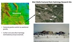
/
Blair Wallis Fractured Rock Hydrology Research Blair Wallis Fractured Rock Hydrology Research

Blair Wallis Fractured Rock Hydrology Research - PowerPoint Presentation

pasty-toler
pasty-toler . @pasty-toler
Follow
382 views
Uploaded On 2017-07-17

Blair Wallis Fractured Rock Hydrology Research - PPT Presentation

Wyoming Fractured granite amp metamorphic rock overlain by weathered granite Surface and subsurface hydrology dominated by spring snowmelt httpwwwjusttrailscomtagvedauwoo Blair Creek ID: 570937

blair water 105 pvc water blair pvc 105 shermanclassic 2015 2016 granite airlifted coring air rotary amp downhole w41

Share:

Link:

Embed:

Download Presentation from below link

Download Presentation The PPT/PDF document "Blair Wallis Fractured Rock Hydrology Re..." is the property of its rightful owner. Permission is granted to download and print the materials on this web site for personal, non-commercial use only, and to display it on your personal computer provided you do not modify the materials and that you retain all copyright notices contained in the materials. By downloading content from our website, you accept the terms of this agreement.


Presentation Transcript

Slide1

Blair Wallis well field:

boreholes completed in both saprolite (eroded granite & metamorphic rocks) & underlying bedrock;

Bedrock wells: BW1-BW9;

Government Gulch:

Wells completed in basement granite and overlying basin fills at the mountain front;

High

Plains

Aquifer

Belvoir Ranch wells:

(Casper Fm.) bedrock wells, shallow riparian wells, & stream gages – all in the outcrop area at the mountain front;

Research wells:

ATLAS TCE plume in High Plains:

Drawing is not to scale: the plume is about 1 mile wide, 10 miles long, and a few hundred feet deep.

Laramie

(UW)

Laramie Range

WY

CO

Cheyenne

http://geofaculty.uwyo.edu/yzhang/

Slide2

Blair Wallis Fractured Rock Research Well Field

Geology

: fractured granite & metamorphic rock overlain by weathered granite;

Hydrology: SW/GW dominated by snowmelt. Hydrological research:

SW/GW monitoring; well tests (single & cross-hole); borehole profiling (

FLUTe liner, televiewer, flowmeter logs); Geophysical research: borehole & surface (seismic, resistivity, GPR, NMR, gravity, etc.)

Petrophysics research: from field to mountain scale;Slide3

Blair Wallis Fractured Rock Hydrology Research

Wyoming

http://www.justtrails.com/tag/vedauwoo/Slide4

Blair Creek

wetland

Regional view

Blair Creek

Well field

Granite outcrop

Granite outcrop

Granite outcrop

Lineaments

0

1

2

km

N

Medicine Bow

National Forest

Wetland

Outcrop

Weather granite (

saprolite

)Slide5

Blair Wallis Fractured Rock Hydrology Research Well Field

BW 6, 7, 8, and 9 were drilled in Fall 2016: cross-hole communication is observed with BW1

Blair Creek

wetlandhttp://geofaculty.uwyo.edu/yzhang/files/Blair_Hydraulics_Research.pdfhttp://geofaculty.uwyo.edu/yzhang/files/Summary_HydraulicTests_2015.pdfhttp://geofaculty.uwyo.edu/yzhang/files/Step_test_BW6.pdf

0

100

200

m

NSlide6

Drilling at Blair

Coring at BW5 (Jordan Hayes)

Setting surface casing made of PVC at BW6

Saprolite Samples & NMR porosity profile in saprolite (Brady Flinchum)Slide7

Bedrock cores: Classic Sherman

Bedrock cores: Sulfide-Rich Sherman from BW4Slide8

BW-1

BW-2

BW-3BW-4BW-5BW-6

BW-7BW-8BW-9Coord.41.183939° N, 105.394125° W41.183888° N, 105.397732° W41.185873° N, 105.399440° W41.184046° N, 105.393329° W41.184099° N, 105.398273° W 41.183842° N, 105.394332° W 41.183989° N, 105.394456° W41.183904° N,105.394667° W41.183753° N,105.394551° WTD (m)30.27

16.0339.1058.6139.02

60.7672.83

76.260.96

Casing depth (m)17

6.16.79.818

17.0717.07

16.76

17.07Casing diameter (

inch)7’’ steel casing7’’ pvc casing7’’ pvc casing

4’’ pvc casing4’’ pvc casing6’’ pvc casing6’’ pvc casing

6’’ pvc casing

6’’

pvc casing

Borehole diameter*1 (inch

)4 7/8’’5.5’’

5.5’’~3.8’’~3.8’’5’’

5’’5’’

5’’Rock type

Classic ShermanClassic Sherman

Classic Sherman

Sulfide-rich Sherman

Classic Sherman

Classic Sherman

Classic Sherman

Classic Sherman

Classic Sherman

DTW

(m)

*2

11.8 (8/15/2015)

11.03

(11/18/2015)

5.7

(9/11/2015)

11.7

(11/18/2015)

10.9

(9/11/2015)

13.18 from toc

(9/8/2016)

12.645

bgs

(8/31/2016)

11.835

from toc?

(9/8/2016)

11.755

bgs

(9/1/2016)

13.743 (12/8/2016)

12.947

(12/8/2016)

*1 This is diameter of the open borehole

beneath

the casing (see the diagram on previous page; also see caliper logs); *2 From top of casing (TOC) unless it is labeled as

bgs

(below ground surface); continuous WL monitoring is available since May, 2015. *3 No

corings

for BW 6, 7, 8, and 9. Note most shallow

saprolite

wells (Brady’s; Austin’s) in Blair Wallis were drilled using the

backpack

shaw

drill.

Drilling method

air/water rotary +coring; airlifted;

air/water rotary +coring;

not developed

wireline+coring

(drilled with water);

not developed

wireline+coring

(drilled with water);

airlifted;

wireline+coring

(drilled with water);

airlifted;

air/water rotary

+

downhole hammer

*3

airlifted;

air/water rotary

+

downhole hammer;

airlifted;

air/water rotary

+

downhole hammer;

airlifted;

air/water rotary

+

downhole hammer;

airlifted;Slide9

Numerous bedrock fractures, variable orientations, observed in cores & logs;

Short-term pumping tests (up to 44 hr

): (1) low to moderate productivity; (2) fresh water (TDS<150 mg/l); (3) a few wells produced suspended sediments (granite minerals & clay);

Well Field Observations28 hr pumping test @ 20 gpm;Total drawdown in BW4 is ~12 m;BW1, 60 m away, had no response;

Slug tests (BW1-9): bedrock equivalent KH: 10-7~10-4

m/s (fine-medium sand);

FLUTe K profile (BW 5, 6, 7): (1) 10

-8~10-5 m/s; (2) hydraulically active zone down to 53 m depth;

Mean bulk fracture porosity: 0.04%;Fracture (ambient) flow velocity: 0.4~80 m/day;

Cross-hole interference tests (BW 1, 6, 7, 8): differential drawdowns for each test

 strong heterogeneitySlide10

Surface casing

(saprolite)

Weathering front?Slide11

BW 7 Test

Sediments cause pumping rate to reduce;

Drawdown stabilization after 44 hr: water-supply BC? Blair Creek (30 m E of well field) ran dry ~ 1 week days later;

Differential drawdowns observed in nearby wellsSediment productionSlide12

BW-4

:Lies in a different type of granite;A low-k underground dyke likely exist as a flow barrier between BW-4 and the rest of the well field;

A geomechanical response was likely observed in BW1 during the 28-hour pumping test of BW-4 (

http://geofaculty.uwyo.edu/yzhang/files/Summary_HydraulicTests.pdf );Has the highest k based on limited well test data among the bedrock wells;Has developed significant deformation, see downhole camera recording when transducer in BW-4 was temporarily stuck:https://uwy-my.sharepoint.com/personal/yzhang9_uwyo_edu/_layouts/15/guestaccess.aspx?guestaccesstoken=DgcVW0DN5N9iSlk5q%2f0CzUvqZZ4Om5%2fYO0QE8LuxvrQ%3d&docid=12513c8803b9f4f38a3a4f4eb25cffe2a&rev=1 Slide13

Discharge

: GW flow to basin is estimated at

6~19% of the total precipitation over the Range, assuming K at Blair extends to mountain scale.

Recharge: GW level dominated by annual snowmelt; connectivity to surface.Recharge & DischargeSlide14

The water level becomes the initial condition for launching the integrated SW/GW simulation.

Estimated WL constrained

by Lidar DEM & GW inversion

Estimated GW flow direction assuming a tensorial fracture network effective (continuum) hydraulic conductivity. Orientation is for schematic only. Well tests will determine the large scale KHx/KHy. Slide15

Borehole Geophysics for BW1—BW9 (known to Ye):

Caliper logs;Downhole NMR;

Sonic velocities; OBI logs;acoustic

televiewer logs;Spinner & heat flowmeter logsVSP;Electrical resistivity (?);GPR (?);ABI Amplitude Kx-filtered horizontal fracture (Courtesy of Brad Carr);Slide16

Seismic refraction;

Surface NMR;Electrical Resistivity; GPR;

Subsurface interpretation from seismic refraction data (Curtesy of Brady

Flinchum)Surface Geophysics (known to Ye):Well fieldModeled seismic P wave velocityInterpolated average water level from 4 boreholesSlide17

(a) Lidar

t

opography of Blair

Wallis well field. (b) Interpreted interface between saprolite and fractured granite by extracting the 1.2 km/s P-wave velocity contour from a kriged

volume (Flinchum

, 2017). (c) Interpreted interface between fractured granite and

less fractured

protolith by extracting the 4.0 km/s surface (

Flinchum

, 2017). (d) A geological model of the well field (vertically

exaggerated 4 times) based on (a), (b),

c)

. The fractured bedrock is ~ 4× the thickness of the saprolite*. (e) A N-S cross section through (d). (e) An E-W cross section through (d).

* In the geological model (d), the protolith layer is not shown, as we don

t yet know

the thickness of this layer.