/
Crimping Instructions Fischer Connectors SA SaintPrex Switzerland Phone      Fax     Crimping Instructions Fischer Connectors SA SaintPrex Switzerland Phone      Fax

Crimping Instructions Fischer Connectors SA SaintPrex Switzerland Phone Fax - PDF document

pasty-toler
pasty-toler . @pasty-toler
Follow
593 views
Uploaded On 2015-03-12

Crimping Instructions Fischer Connectors SA SaintPrex Switzerland Phone Fax - PPT Presentation

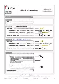
fischerconnectorscom mailfischerconnectorsch Assembly Instructions Document No 60000451 Date 22 Nov 2013 Rev 26 Established by TGN Approved by SKE Fischer Connectors SA All rights reserved This document is the property of Fischer Connectors SA ID: 44502

fischerconnectorscom mailfischerconnectorsch Assembly Instructions Document

Share:

Link:

Embed:

Download Presentation from below link

Download Pdf The PPT/PDF document "Crimping Instructions Fischer Connectors..." is the property of its rightful owner. Permission is granted to download and print the materials on this web site for personal, non-commercial use only, and to display it on your personal computer provided you do not modify the materials and that you retain all copyright notices contained in the materials. By downloading content from our website, you accept the terms of this agreement.


Presentation Transcript

-Barrel dimensions and stripping length P/N AWG Section 2a Overall Product Range • Crimp contacts•Recommended crimp tool settings• Crimping and assembly tools-Wire size and tool chart-Table 1b-Table 3b -Barrel dimensions and stripping length P/N AWG Section 2b Only for UltiMate™ Size 08 and 11 • APPENDIX 1 -Wire size 16 • Assembly in connector17 Section 3 Page 1 of 18 This document provides general guidelines and procedures for understanding and achieving reliable crimp terminations when using Fischer Connectors closed barrel crimp contacts.Its contents may slightly differ from individual company guidelines and procedures, and is not intended to replace them.Given the broad variety of cable sizes, stranding and qualities, it is always recommended to perform trials to verify and if necessary adapt the procedure to the particular situation and application.If a conflict occurs between this document and Fischer Connectors' catalogues, this document will take precedence. SCOPE Document No. 600.00.451Rev : 2.6The connection between the wire and the terminal is a critical element of any wire termination.A good termination is important because it ensures mechanical integrity and electrical performances required for the applicatioCrimping is one common method of achieving this connection. It occurs inside the crimp barrel (terminal) of the contact.There are two types of barrels -open and closed. This specification only deals with closed barrels because all contacts referred in this document are screw-machined which is the usual process for producing this type of barrel.Wire sections are expressed in AWG (American Wire Gauge), mmor CMA (Circular Mil Area). See conversion table in Appendix 1Because the wire stranding and insulation type or thickness can vary widely within a particular wire size, it is very important to carefully verify the compatibility between the selected wire and the crimp contact by checking the barrel hole dimensions in Table 1aTable 1b for UltiMate™ Size 08 and 11.Wire types:Stranded conductors shall be used for crimping.Solid round conductors may only be used when their suitability has been proven.The end result of a properly crimped terminal is a reliable mechanical and electrical connection.StrandedSolid Parts of a machined Fischer Connector crimp contactConductor crimp areaInspection windowContact retaining spring mechanism in contact blockMating interface (male or female) a b c d Crimping Instructions Assembly Instructions Note 1: This spring mechanism is not present on crimp contacts for Fischer UltiMate™ Size 08 & 11 products.For this reason be removed from the contact block by means of extraction tools. 1) Section 1Page 2 of 18 Crimp Tool ULTRA PRECISIONfor closed crimp termination BALMAR 18 -000DANIELS MH -800 Part Number C Crimp Tool Ø0.5 Ø0.9 Ø1.3 Ø1.6 ASTRO TOOL 615708 The best choice of precision crimp tools for highly reliable eight indenter crimping per US-MIL, IEC and DIN Specifications.These hand tools have an integral mechanism to control the crimping operation to the extend that, once the crimping operation has been started, the crimping tool cannot be opened until the crimping cycle has been completed (full-cycle/ratcheting tool).Positioners have to be ordered according to contact.Table 1aIEC 60203 / DIN 41 611, Part 3MIL-C-22520, Class I, Type CRIMPING AND ASSEMBLY TOOLS Document No. 600.00.451Rev : 2.6 Contact Insertion Tool Part Number Ø0.5 Ø0.9 Tool for inserting male and female removablecrimp contacts into the contact block.Especially recommended for small gauge and fragile wires.POM (black Delrin®)Tool Steel, chrome plated TX00.210 TX00.211 TX00.273 Contact Extraction Tool Part Number Ø0.5 Ø0.9 Tool for extracting male and female removablecrimp contacts from the contact block.The sleeve of this tool is pushed over the contact, thereby releasing the contact retaining mechanism. The tool plunger is then pushed to eject the TX00.205 TX00.212 Material-Handle:-Fork:POM (black Delrin®)Tool SteelMaterial-Housing and Plunger:-Sleeve:-Slide: Assembly Instructions Section 2a7 of 18 -Barrel dimensions and stripping lengthTable 2a P/N AWG CONTENTS Crimping Instructions CRIMP CONTACTS Crimping Instructions Document No. 600.00.451Rev : 2.6MaleFemaleAssembly InstructionsLegendCompatible Crimp style connectors are supplied with the appropriate quantity of crimp contacts. However, replacement contacts may be ordered according to table below.Crimp contacts cannotbe removed from the contact block by means of extraction tools. All dimensions shown are in millimeters and are for reference only. Polarit Contact Size Part Numbe r A Barrel dimensions B C All contacts below are injected insulating support style crimp contacts. Stripping lengthWire Size and Tool Chart Barrel Dimensions and Stripping Length Note 1: Exceptionally for a given AWG, the diameter of some stranded conductor designs could be larger than the hole diameterofthe crimp barrel.Make sure that the conductor diameter fits into the hole. See barrel dimensions in below. Positione ContactCrimp Tool UltiMate Size 200.2895200.2896 Part Numbe r -- Replaces TX00.240 MaleFemalePolarit Ø0.7 TX00.301TX00.370 • • • Sizee08111318--Part NumberPart Numbe r Wire Size A WG 28-24TABLE 1bTABLE 2bThe wire insulationshall fit into D2. 1) Female Ø0.7 Male 200.2895 3.40.63.10.62(0.024") (0.134'')(0.024'')(0.122'')(0.039'')(0.110'') 0.65(0.026") BD2 Inspection window Sect. 2b Only for UltiMate™ Size 08 and 11Page 9 of 18 AWG CONTENTS Crimping Instructions CONTENTS Fischer Connectors SASaint-Prex, SwitzerlandPhone +41 21 800 95 95Fax+41 21 800 39 24www.fischerconnectors.commail@fischerconnectors.ch Instructions Document No. 600.00.451Rev : 2.6© Fischer Connectors SA / All rights reservedThis document is the property of Fischer Connectors SA. All communications to third parties or the reproduction in any form, even partial, are prohibited without our written consent. Page • APPENDIX 1 -Wire size • Crimp process-Preparation-Stripping-Strand damage and end cuts-Wire insulation damage-Cleanliness-Conductor deformation/birdcaging-Examples of stripping faults-Crimping-Conductor location-Deformation of the crimp barrel-Mechanical properties of the crimped connection-Methods for building up conductor cross-section