/
Background, design and construction of a Background, design and construction of a

Background, design and construction of a - PDF document

phoebe-click
phoebe-click . @phoebe-click
Follow
414 views
Uploaded On 2016-08-07

Background, design and construction of a - PPT Presentation

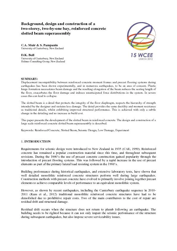
two storey two by one bay reinforced concrete slotted beam superassembly CA Muir S Pampanin University of Canterbury New Zealand D K Bull University of Canterbury New Zealand ID: 437513

two - storey two - by - one bay reinforced concrete

Share:

Link:

Embed:

Download Presentation from below link

Download Pdf The PPT/PDF document "Background, design and construction of a" is the property of its rightful owner. Permission is granted to download and print the materials on this web site for personal, non-commercial use only, and to display it on your personal computer provided you do not modify the materials and that you retain all copyright notices contained in the materials. By downloading content from our website, you accept the terms of this agreement.


Presentation Transcript

Background, design and construction of a two - storey, two - by - one bay, reinforced concrete slotted beam superassembly C.A . Muir & S. Pampanin University of Canterbury, New Zealand D . K . Bull University of Canterbury, New Zealand Holmes Consulting Group, New Zealand SUMMARY : Displacement incompatibility between reinforced concrete moment frames and precast flooring systems during earthquakes has been shown experimentally, and in numerous earthquakes, to be an area of concern. Plastic hinge form ation necessitates beam damage and the resulting elongation of the beam reduces the seating length of the floor, exacerbates the floor damage and induces unanticipated force distributions in the system. In severe case s this can lead to collapse. The slott ed beam is a detail that protects the integrity of the floor diaphragm, respects the hierarchy of strength intended by the designer and sustains less damage. The detail provides the same ductility and moment resistance as traditional details, whilst exhibi ting improved structural performance. This is achieved with only a subtle change in the detailing and no increase in build cost. This paper presents the development of the slotted beam in reinforced concrete. The design and construction of a large scale r einforced concrete slotted beam superassembly is described. Keywords: Reinforced Concrete , Slotted Beam, Seismic Design, Low Damage, Experiment 1. INTRODUCTION Requirements for seismic design were introduced to New Zealand in 1935 ( CAE, 1999 ) . Reinforced concrete has remained a popular construction material since this time, and throughout subsequent revisions. During the 1960’s the use of precast concrete construction gained popularity throug h the introduction of precast flooring systems. This was followed by a rapid increase in the use of precast elements as part of the primary lateral load resisting system in the 1980’s. Building performance during historical earthquakes, and extensive labo ratory tests, have shown that well detailed monolithic reinforced concrete structures perform well during large earthquakes. C onstruction methods with precast concrete have evolved to primarily involve joining together precast elements to achieve comparabl e levels of performance to an equivalent monolithic system. However, as shown by recent earthquakes, including the Canterbury earthquake sequence in 2010 - 2011 ( Kam et al., 2012 ) traditional monolithic reinforced concrete structures have had to be demolished due to prohibitive repair costs. Two of the main contributors to the cost of repair are residual drift and structural damage. Residual drift occurs when the structure does not return to plumb following an earthquake. The building needs to be righted because it can not only impair the seismic performance of the structure during subsequent earthquakes, but a lso impose severe serviceability issues. Structural damage within a monolithic concrete moment resisting frame primarily stems from plastic hinge zones. In a traditional monolithic structure the energy is dissipated through alternative tensile and compre ssive yielding of the top and bottom longitudinal reinforcement over loading reversals. This mechanism results in there being a n offset in the neutral axes at the beam ends, this geometry results in beam elongation. Shear transfer through a plastic hinge z one is by way of equivalent truss mechanism. The horizontal component of the diagonal shear strut causes tensile forces, and hence strains, to be larger than compressive. These accumulating tensile strains cause a further material contribution to beam elon gation. The cumulative effect of combined geometric and material contributions to beam elongation is the potential to form an unintended inelastic mechanism and tearing of the floor diaphragm. Floor diaphragm damage has been shown to inhibit lateral force transfer and in extreme cases cause floor collapse ( Bull, 2004 ; Matthews, 2004 ) . These deficiencies with current design in reinforced concrete need to be rectified. Efforts to date have primarily focussed on developing low damage connection using dry jointed ductile connections or PREcast Seismic Structura l System (PRESSS) technology ( Pampanin, 2005 ; Priestley, 1996 ; Priestley et al., 1999 ) . Whilst these systems directly address connection damage they require additional solutions to limit floor and column damage caused by beam elongation. There can be a cost premium to use this type of system that can make it comparatively less attractive to a client. 2. BACKGROUND The slotted beam is a solution which addresses the issues inherent of traditional design in reinforced concrete. The concept was first proposed during the PRESSS research programme in the form of the UT - GAP connection ( Palmieri et al., 1996 ) , shown in Figure 2. 1 (a) and TCY - Gap connection ( Priestley, 1996 ; Priestley, et al., 1999 ) . This connection provided a 1” slot extending ¾ down the column face. This forced rotation to occur about the bottom of the beam, constraining plasticity to the top longitudinal reinforcement. Th e connection performed satisfactorily and was developed throughout the PRESSS programme to include post - tensioning to provide a more direct force transfer. This connection reduces beam elongation; however it is likely to damage the floor diaphragm due to g ap opening occurring at the top of the beam. It was noted during the PRESSS program that inverting the connection would resolve this issue ( Palmieri, et al., 1996 ) . (a) UT - GAP connection dev eloped during PRESSS program ( Palmieri, et al., 1996 ) . (b) Early Japanese reinforced concrete slotted beam ( Ohkubo et al., 1999 ) . Figure 2 . 1 . Early slotted beam concepts. The slotted beam for insitu reinforced concrete was proposed at a similar time in Japan ( Matsuoka & Ohkubo, 1996 ) . An early schematic of the system is shown in Figure 2.1 (b). A slot extending approximately ¾ up the column face is provided which constrains rotation to occur about the top concrete hinge for both p ositive and negative flexure. The top longitudinal reinforcement is stronger than the lower to limit strain, and hence cracks and elongation at the top concrete hinge . Moment resistance and energy dissipation is provided by tension and compression yiel ding of the bottom longitudinal reinforcement. A portion of the lower longitudinal reinforcement is unbonded to spread the plastic strains over the length of the bar, rather than accumulating potentially excessive strain over the short length of bar spanni ng the gap . Shear transfer is facilitated via diagonal hanger bars anchored in the columns. The fixed end rotation occurring about the top concrete hinge at both ends simultaneously dramatically reduces the geometric contribution to beam elongation. Simil arly, the reduction in cracking and the recovery of tensile strain in the bottom reinforcement reduce the material contribution to beam elongation. The net effect is a reduction in beam elongation to approximately 12% that of an equivalent monolithic beam ( Au, 2010 ; Ohkubo & Hamamoto, 2004 ) . Subsequent research by Ohkubo and Hamamoto ( 2004 ) tested cruciform subassemblies with cast insitu floor slabs. A benchmark monolithic connection was compared to a slotted to determine the differences in damage. The slotted be am displayed a stable response and resulted in significantly less damage to the frame and floor. This is shown in Figure 2.2. (a) Slotted specimen . (b) Traditional specimen . Figure 2. 2 . Damage to frame and in - situ floor ( Ohkubo & Hamamoto, 2004 ) . Research on the slotted beam concept at the University of Cante rbury has built on the above research, both for precast systems and cast insitu. Amaris et al . , ( 2008 ) investigated a recentring slotted beam connecti on which incorporated precast construction, a structural steel top hinge, external energy dissipaters and post - tensioning. The set up for this experiment is shown in Figure 2.3 (b). Satisfactory performance was observed, however constructability and econom ic issues were highlighted. Recent research by Au ( 2010 ) , Leslie ( 2010 ; 2010 ) and Byr ne ( 2012 ) has concentrated on investigating the slotted beam parametrically, analytically and experimentally. Leslie ( 2010 ) focussed on developing and experimentally valida ting a variety of precast or semi - precast concrete slotted beam details. The set up for this experiment is shown in Figure 2.3 (a). This research showed that fabricated steel top hinges could deform excessively in shear, hastening buckling of the lower lon gitudinal reinforcement. It was found that the use of high strength lower longitudinal reinforcement could reduce residual drifts. However, use of high strength steel c an result in large bond demands, particularly through the beam - column joints. (a ) Two - dimensional, two - bay, frame test by Leslie ( 2010 ) . (b ) Two - dimensional, two - storey, frame test by Amaris et al., ( 2008 ) . Figure 2 .3. Slotted beam experiments conducted at the University of Canterbury. Au ( 2010 ) focussed on developing and testing an appropriate slotted reinforced concrete beam connection that can be used a s a substitute for conventional monolithic reinforced concrete co nnections in New Zealand. An extensive theoretical investigation into slotted beam mechanics produced new design recommendations. Four specimens were tested experimentally, one benchmark monolithic and three slotted. Over the course of testing these specim ens several details were improved to enhance performance, such as : restraint of unbounded reinforcement, beam torsion restraint, joint shear reinforcement and bottom longitudinal reinforcement bond requirements. The final test specimen, SB3, which incorpor ated these refinements , is shown in Figure 2. 4 . This specimen exhibited very satisfactory performance. (a ) Front elevation. (b) Side elevation. Figure 2 . 4 . Specimen SB3 tested by Au (2010). Recently, research by B yrne ( 2012 ) has investigated joint shear and bottom longitudinal reinforcement bond mechanics. A parametric investigation was undertaken and the results tested in two cruciform subassemblies. Extremely satisfa ctory performance was observed. The effective column depth recommended by Au ( 2010 ) was reduced, as were the joint shear requirements . 3. SPECIMEN DESIGN R esearch to date has focussed on the connection mechanics. This has been investigated param etrically, numerically and experimentally using beam - column joint subassemblies or two - dimensional frame systems . These types of specimens are purposefully simplified to prevent the data being influenced by outside factors that are not being examined. This configuration lends itself well to trialling many details in a time and cost effective manner in order to develop satisfactory performance and refine design recommendations. However, to be able to fully evaluate the performance of the reinforced concrete slotted beam system , complex three - dimensional interactions between the lateral load resisting system and the floor diaphragm need to be assessed. (a ) Prototype structure. (b) Superassembly SA1 extracted from pr ototype. Figure 3.1. Three - dimensional reinforced concrete slotted beam superassembly and origin. Specimen SA1 is a large scale three - dimensional reinforced concrete slotted beam superassembly designed to provide data on interaction between structural elements in a realistic New Zealand building geometry. An oblique of the superassembly is shown in Figure 3.1 (b). It will also allow the development of connection details intended to improve performance and robustness. It will serve to confirm whether the damage to the floor diaphragm is reduced, and to what extent, when the slotted beam detail is used. The project will also allow the practicality of the system to be assessed and serve as a showpiece to increase familiarity of the construction industry wit h this emerging detail. The two - storey, two - by - one bay, superassembly was extracted from the first and second stories of the prototype building shown in Figure 3.1 (a). The specimen is scaled geometrically at 2/3 according to a ‘practical real model’ phil osophy ( Harris & Sabnis, 1999 ) . This was the maximum size that could be accommodated within the structural extension laboratory at the University of Canterbury. N (a) Grid 1 elevation. ( b ) Grid A elevation. Figure 3 . 2 . Three - dimensional reinforced concrete slotted beam superassembly and origin. As can be seen in Figures 3.2 (a) and (b), the floors on both stories are prestressed precast unit s , with the first storey using hollow - core and the second dapped double - tee . This specimen has been designed to closely replicate how a typical structure in New Zealand would be designed and constructed using the slotted beam configuration. Hence, design was undertaken to NZS3101:2006 ( Standard Association of New Zealand, 2006 ) . However, given that the Standard was not written with the intent of being applied to this type of structure, some aspects were based on recommendation s f rom recent research and first principles. As such, these types of structures lie o utside of the current standard. There are many aspects in the design of the slotted beam that require special detailing to ensure sa tisfactory performance, such as: diagona l shear hangers, joint shear reinforcement, lower longitudinal reinforcement bond, local unbond ed length and antibuckling restraints . Many of these details can be seen in Figures 3.3 (a ) and (b). This list is not exhaustive and t here is not space in this p aper to discuss them at length. Nor is this paper intended as a design guideline. ( a) Three - dimensional rendering of reinforcement detail. (b ) Precast drawing of ex terior first storey connection. Figure 3 . 3 . Precast component manuf acturing. Tolerances with the slotted connection are critical to satisfactory performance. Of particular importance is the location of the diagonal hangers, unbonding and antibuckling tubes and slot form. The cage should be checked by the engineer prior to casting. 4. SPECIMEN CONSTRUC TION Specimen SA1 was designed to be largely precast to reduce erection time and labour requirements. Furthermore, it was important to the project to assess the practicality of construction using the slotted beam detail, especially when compared to a traditional detail. Hence, the manufacture of the precast units was undertaken by a reputable commercial precast company. ( a) Reinforcement cage in form prior to concrete pour. ( b ) Level one precast componen ts arriving outside laboratory. Figure 4. 1 . Precast component manufacturing. The feedback from the precast company was invaluable and, on the whole , it was very positive. The issues encountered were often around forming the slot itself and tolerance, especially co ncerning the diagonal hanger bars and stirrups. This location and sealing of the unbonding steel tubes around the lower longitudinal reinforcement was sometimes an issue due to the accessibility once the reinforcement cage was in the forms. The assembled r einforcement cage in the form can be seen in Figure 4.1 (a). The employees of the precast company commented that the job was challenging, but not as difficult as some other traditional details that they have worked on. The prestressed precast floor units w ere sourced from a local supplier, and are no different to that used in a traditional monolithic structure. It can be concluded that the slotted beam can be effectively manufacturer by reputable precast companies in a similar manner to traditional details. The specimen, being completely precast, was delivered in components and join ed together through grouting Drossbach tubes and casting mid - beam splices. The precast components for the first storey can be seen arriving outside the laboratory in Figure 4.1 (b). Th e size of these components was dictated by the width of a standard truck and the door to the laboratory. The construction stages are shown in Figures 4.2 (a) – ( d ). This method of construction enables rapid erection with a smaller workforce. However, care must be taken in assuring the quality of connections. (a ) First floor precast components set out. (b) First floor in - situ topping pour complete. (c) Second floor precast components being grouted . (d) Completed specimen SA1. Figure 4.2. Construc tion stages of reinforced concrete slotted beam superassembly SA1. The erection of this specimen took place during a seismically active period in Christchurch. As such, significant time and cost were expended on the propping design . This conservative app roach was validated during the February 22 nd aftershock, and following sequence of aftershocks. Only minor displacement of ungrou ted precast components was observed and some minor cracking. This paper is intended to be read in conjunction with the compani on paper on the experimental methods and results presented at this conference by Muir et at., ( 2012 ) . 5. CONCLUSIONS The background to the development of the reinforced concrete slotted beam has been described. The design and construction of the slotted beam superassembly has been presented. It has been demonstrated that design and construction of reinforced concrete structures using the slotted detail is compa rable to using traditional details. The detail can be manufactured accurately and economically by reputable precast companies. Extensive use of precast can reduce erection time and labour demand. ACKNOWLEDGEMENTS This research was made possible by suppo rt provided by the New Zealand Foundation for Research, Science and Technology through the Future Building Systems research programme. The materials, support and equipment provided by the University of Canterbury are gratefully acknowledged. Thanks are ext ended to University of Canterbury technicians Mr Russell McConchie, Mr Gavin Keats and Mr Peter Coursey. The involvement of industry was integral to the success of this project; as such the authors would like to acknowledge the support and enthusiasm of Ho lmes Consulting Group, Holmes Solutions, Bradford Precast Limited and Fulton Hogan Stahlton Limited. REFERENCES Amaris, A., Pampanin, S., Bull, D. K., & Carr, A. J. (2008). Experimental Investigation on a Hybrid Jointed Precast Frame with Non - tearing Floor Connections. New Zealand Society for Earthquake En gineering Conference. Au, E. (2010). The mechanics and design of a non - tearing floor connection using slotted reinforced concrete beams. University of Canterbury, Christchurch, New Zealand. Bull, D. K. (2004). Understanding the complexities of designing d iaphragms in buildings for earthquakes. Bulletin of the New Zealand Society for Earthquake Engineering , 37(2) , 70 - 88. Byrne, J. D. R. a. B ull ., D. K. (2012). Design and testing of reinforced concrete frames incorporating the slotted beam detail. New Zealand Society for Earthquake Engineering. CAE. (1999). Guidelines for the use of structural precast concrete in buildings. Christchurch, New Zealand: Centre for Advanced Engineering. Harris, H. G., & Sabnis, G. M. (1999). Structural modell ing and experimental techniques (2 ed.): CRC Press, Boca Raton, London, New York and Washington D.C. Kam, W. Y., Pampanin, S., & Elwood, K. (2012). Seismic Performance of Reinforced Concrete Buildings in the 22 February Christchurch (Lyttelton) Earthquake. Bulletin of the N ew Zealand Society for Earthquake Engineering , 44(4) . Leslie, B. J. (2010). The development and validation of a non - tearing floor precast concrete structural system for seismic regions. University of Canterbury, Christchurch, New Zealand. Leslie, B. J., Bull, D. K., & Pampanin, S. (2010). The Seismic Performance of a Non - Tearing Floor Precast Concrete Structural System. New Zealand Society for Earthquake Engineering Conference . Matsuoka, T., & Ohkubo, M. (1996). Energy Dissipation Mechanism Controlled Bo ttom Rebar Yielding at Beam - end . Summaries of technical papers of the Annual Meeting Architectural Institute of Japan . C - 2 , Structures IV, Reinforced concrete structures prestress ed concrete structures masonry wall structures. Matthews, J. G. (2004). Hollow - core floor slab performance following a severe earthquake. University of Canterbury, Christchurch, New Zealand. Muir, C. A., Bull, D. K., & Pampanin, S. (2012). Experimental me thod and results from testing of a two storey, two - by - one bay, reinforced concrete slotted beam superassembly. 15th World Conference on Earthquake Engineering. Ohkubo, M., & Hamamoto, T. (2004). Developing reinforced concrete slotte d beam structures to reduce earthquake damage and enhance seismic structural performance. 13th annual World Conference on Earthquake Engineering. Vancouver. Ohkubo, M., Matsuoka, T., Yoshioka, T., & Anderson, D. L. (1999). Shear transfer mechanism of reinforced concrete beams with a slot at the beam - end. Proceedings of Japan Concrete Institute , 21(3) , 301 - 306. Palmieri, L., Saqan, C., French, C., & Kreger, M. (1996). Ductile connections for precast concrete frame systems. ACI, 162, 313 - 35 6. Pampanin, S. (2005). Emerging Solutions for High Seismic Performance of Precast/Prestressed Concrete Buildings. Journal of Advanced Concrete Technology , 3(2) , 207 - 223. Priestley, M. J. N. (1996). The PRESSS program - Current status and proposed plans fo r phase III. PCI Journal , 41(2) , 22 - 40. Priestley, M. J. N., Sritharan, S., Conley, J. R., & Pampanin, S. (1999). Preliminary results and conclusions from the PRESSS five - storey precast concrete test building. PCI Journal , 44(6) , 42 - 67. Standard Associatio n of New Zealand. (2006). Concrete Strucutures Standard, New Zealand Standard NZS3101. Wellington, New Zealand.