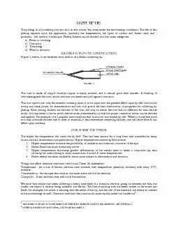
/
HAPPY TIP TIPS  The plating on all soldering iron tips will, in due co HAPPY TIP TIPS  The plating on all soldering iron tips will, in due co

HAPPY TIP TIPS The plating on all soldering iron tips will, in due co - PDF document

phoebe-click
phoebe-click . @phoebe-click
Follow
514 views
Uploaded On 2015-10-27

HAPPY TIP TIPS The plating on all soldering iron tips will, in due co - PPT Presentation

1 This seems to be one of those things that everybody knows but nobody has measured See appendix A 2 Appendix B gives a bit more detail for those who want it copper corespecial iron platingchrom ID: 173775

This seems

Share:

Link:

Embed:

Download Presentation from below link

Download Pdf The PPT/PDF document "HAPPY TIP TIPS The plating on all solde..." is the property of its rightful owner. Permission is granted to download and print the materials on this web site for personal, non-commercial use only, and to display it on your personal computer provided you do not modify the materials and that you retain all copyright notices contained in the materials. By downloading content from our website, you accept the terms of this agreement.


Presentation Transcript

HAPPY TIP TIPS The plating on all soldering iron tips will, in due course, fail, even under the most benign conditions. The life of this plating depends upon the application (specially the temperature), the types of solders and fluxes used, and - primarily - the operator's technique. Plating failures can be divided into four main categories: a) Stress or cracking. b) Corrosion. c) 'Dewetting'. d) Wear or abrasion. Soldering iron tip construction. Figure 1, below, is an idealised cross-section of a Hakko soldering tip. FIGURE 1. The core is made of copper because copper is easily worked, and to ensure good heat transfer. A flashing of chromium guards the iron (which we have not mentioned yet) against corrosion. The iron layer is not only the essential working layer; it is the layer with the greatest effect upon tip life. Iron has its strong and weak points; its characteristics and low cost give it the best combination of properties for soldering tip plating. Most plating failures are failures of the iron; the way in which the iron fails is different for each failure mode. It is important to know which failure mode predominates, so that the proper corrective action can be devised and applied. For example, it is a popular misconception that 'more iron will extend tip life'. While it is true that more iron may preclude failures due to wear or abrasion, it may exacerbate dewetting failures, and will have little if any effect upon cracking. Our enemy the therm. The higher the temperature, the lower the tip life1. This has been known for a long time, and quantified in many books, articles, dissertations and publications. Higher temperatures reduce tip life because: 1. Higher temperatures increase the probability of oxidation and chemical corrosion of the tips. 2. Hotter fluxes are more chemically active. 3. Higher temperatures encourage greater deformation of the metals used to make a composite tip, thus allowing the outer plating to crack sooner than it would at lower temperatures. 4. Hotter metals are more malleable, hence more subject to deformation and abrasion. Things that affect chemical reactions (very broad Chem 1A statements): Temperature - As a rule of thumb, reaction rates increase with temperature, generally doubling with every 10oC. increase. Concentration - the stronger the solution, the more active will be the reaction Catalyst(s) - if any are there they will boost the reaction We must first realise that when soldering is being done there is a chemical reaction going on between the flux, the solder, the object or objects being soldered, and the tip. The flux is reacting with the metal oxides on the board and leads, for example; the solder is reacting with the metal of the tip; and the rest of the materials are taking an interest in the proceedings as well. Chemical reactions take place much more rapidly under hot conditions2 1 This seems to be one of those things that everybody knows but nobody has measured. See appendix A. 2 Appendix B gives a bit more detail, for those who want it. copper corespecial iron platingchromium platingtin coating (solder) Stress or cracking failures. Plating failures due to cracking are caused by too much stress being applied to the tip whilst soldering - that is, the operator is pressing too hard. Many operators believe that, by applying more force to the tip, they will improve heat transfer. This is not so. The best ways to improve heat transfer are, first, to use the largest tip possible on the lead commensurate with access to the joint, which maximizes the contact area, and to use molten solder as a bridge between the tip and the joint. Fine tips are more susceptible to cracking than are heavy tips, simply because they are thinner in cross-section and cannot bear the same load as heavy tips. Iron is susceptible to compression failure; that is, it will crack under pressure. Too much force applied to the plating will cause a crack to form. This crack, if left unattended, will propagate itself through the plating to the copper core. (Think of a block of ice, which, when cracked on the surface, will split.) Thicker plating will not help, as the crack will still propagate. Once the copper core is exposed, solder will erode it rather quickly. This hollows out the tip, which then collapses. A sure sign of a stress failure is a hollowed-out or jagged tip. Bending the tip to change the configuration will damage both the plating and the copper core. Neither the plating nor the core are ductile and will crack if bent. Angled tips are available for all Hakko soldering stations; special order tip configurations are available. Striking the tip against the work-bench or other solid object to dislodge accumulated solder is another way to crack the iron plating. It is not advisable to treat tips carelessly in any case; even accidental knocking of the tip against a hard surface may crack the plating. Soldering iron tips, although not intended for use as pry-bars to dislodge components from boards, are often used as such to the detriment of the tip. Tools appropriate to such tasks are made of hardened steel, and can stand the strain. Tips cannot tolerate the high loads applied, and will crack - sometimes break right off. Do not use tips for purposes other than soldering. Corrosion failures. Corrosioninduced plating failures are primarily related to the flux used with the solder. Iron reacts chemically with acids; fluxes generally contain organic acid or halide additives. The purpose of flux is to improve the flow and 'wettability' of the solder joint; thus, when heated to soldering temperatures, it chemically strips oxides from the metallic parts of the board where it is applied. The more active the flux, the more likely it will be to react with the iron in the tip, weakening it over time. Many water-soluble fluxes, for example, are highly active and typically contain organic acids. A note on fluxes - Selecting a flux involves many factors: long-term solder joint reliability, post-assembly cleaning costs, effectiveness, environmental considerations such as toxicity of the flux and its byproducts, but also the effect of the flux on soldering iron tip life. This can be a significant economic consideration. Another cause of tip corrosion and concomitant failures is contamination on the sponges used to clean the tips. This contamination is usually flux residue, soaked up in the sponge, which reacts with the hot tip when it is wiped across the sponge. Replacing dirty sponges with clean ones, and using only clean water to moisten them, will help prevent this cause of failure. Use distilled water when the tap water has a high mineral content. Ordinary household sponges often contain sulphur, plastics, soap or other materials. Whilst these materials are good in their place, they will react with the tip at soldering temperatures, creating corrosive byproducts that can damage the tip. Use only sponges intended for soldering purposes. An alternative to the sponge is the Hakko 599 metallic tip cleaner, which cannot absorb foreign materials from the tip and does not induce thermal shock. ¤ ¤ note ¤ ¤ When tinning a tip before storing it, always use an RMA or other low-tivity flux core solder. No-clean, water soluble, or acid flux core solders will corrode the tip, even in storage. 'Dewetting' failures. This is the most common form of plating failure. 'Wetting' refers to the ability of the solder to adhere to the metal of the tip (or the part of the tip prepared for accepting solder). Dewetting is largely preventable with proper maintenance, as its primary cause is oxidation of the iron plating. Iron oxide - rust - will not 'wet'; it is also a thermal insulator; its presence on a tip is often the cause of the complaint, 'the tip won't get hot'. Oxidation is a natural result of the soldering process. Flux is used to dissolve the oxide deposits on the tip and leads to allow solder joints to be formed. The chemical reaction of iron and oxygen is accelerated by heat. Free oxygen in the air is the primary cause of oxidation. There are several ways to minimize oxidation: The most effective way is to keep the tip tinned - covered with a protective layer of solder. The solder keeps air away from the iron in the tip. Soldering at lower temperatures slows the chemical process and, as mentioned before, extends tip life in many other ways. Lower temperatures also reduce the probability of damaging the circuit boards. Turn the iron off when it is not being used. Oxidation is greatly accelerated as temperature increases. The Hakko FM2, for example, will heat to operating temperature in just 15 seconds. Other causes of dewetting are: Inadequately active flux, or no flux at all. Users of 'no clean' fluxes and flux-core solders often have this problem; it is not a tip plating problem but rather a process problem involving the interaction between the tip, tip temperature, solder, and flux. Dirty sponges. Sponges accumulate metal and flux residue, which can adhere to the iron plating of the tip; this residue will not wet. Hard water. Some hard water contains chemicals, which can form a bonded, unwettable surface. Deionized or distilled water is recommended in these cases. Detinned or unwettable tips can often be restored by using a commercial tip tinner. There are several such products available; all are chemically active and contain an abrasive to scour the oxide from the tip. Whilst these compounds can clean a stubborn oxide layer from an otherwise good tip, they will by virtue of their characteristics remove some of the iron plating, reducing the remaining life of the tip. Under no circumstances should tip tinner be used as a customary means of maintaining soldering tips. Tips will also accumulate a layer of black 'goo' after being used for a time. This 'goo' is flux residue, and results from partial combustion of the flux during soldering. This residue is a barrier to both effective heat transfer and proper wetting. Proper and frequent cleaning will keep this residue from building up. Wear and abrasion failures. Wear is the expected mode of failure for a soldering tip. Each time a joint is made, friction between the iron plating and the solder joint will cause a slight abrasion at the point of contact. Eventually the plating will wear through, and the tip will show a pinhole on its working surface. Wear, therefore, is unpreventable; its effects can be ameliorated. The effects of wear depend upon two factors: the thickness of the iron plating, and the operators' practice. Plating thickness is largely a function of tip geometry and thermal response. Fine tips will have thinner plating than large ones, for plating that is too heavy can slow thermal response. Tip selection is important; use the bluntest and heaviest tip suitable for the task at hand. Rubbing the tip across the joint, or applying excessive pressure whilst soldering, will increase wear; neither practice increases heat transfer. Dragging the tip across a series of solder joints is another common practice that neither produces good solder joints nor adds to tip life. It is, rather, equivalent to dragging the tip across a file. As the dwell time at each joint is very short, the probability of weak or cold solder joints is greater. Hakko recommends what might be termed 'wipe' soldering, using a knife tip and moving along the line of the leads. NEVER USE ABRASIVE MATERIALS TO CLEAN A SOLDERING TIP. Sandpaper, files, emery cloth, old rags, commercial cleaners all abrade the tip; some can destroy it. Use a Hakko 599 or a clean, damp sponge. Flux is flux, but not always For years and years and years only rosin-based fluxes were used; the operator would put the solder wire on the tip, let it melt, and trickle down to the connection. The relatively recent introduction of water-soluble flux made that impossible. Solder with a watersoluble flux core does not run down the tip. Rather, it wicks up the tip; in time the tip burns and poor solder joints result. A different technique is required. First, heat the joint, then apply the solder on the other side of the joint. After the solder begins to melt, pull it away then remove the iron. Socalled 'no-clean' fluxes are much more chemically active than other fluxes; here, the problem is that there is less flux to do the work of a flux . And, of course, operators must keep the iron tips tinned at all times. If operators do not make a conscious effort to keep the tips tinned the tips will corrode with astonishing speed. These are summarized below for your elucidation and edification… a summary of soldering tip care guidelines. This table brings together the recommendations listed in this section. If these practices are made part of the daily routine, tip life should be increased. CONCERN WHAT TO DO CRACKING ¨ Use the largest tip possible for the lead being soldered. ¨ Do not apply excessive pressure when soldering. Tin the tip for maximum heat transfer. ¨ Do not strike the tip against the work-stand or any other solid object. ¨ Do not use the tip as a screwdriver or pry- CORROSION ¨ Use the least aggressive flux that will do the job. RMA flux is recommended for maximum tip life. ¨ Use the Hakko 599 or a sponge specially made for soldering irons to clean tips. ¨ Do not use dirty sponges. Throw them away and use clean ones. ¨ Moisten sponges with deionised or distilled water. ¨ Tin tips with RMA solder before storing them. Do not use aggressive or water soluble fluxcore solders for this purpose. DEWETTING ¨ Turn the system off when it isn't being used. ¨ Use the lowest possible temperature when soldering to minimise oxidation. ¨ Keep the tips tinned. This keeps air away from the tip and reduces oxidation. ¨ See hints under 'Corrosion'. WEAR ¨ Use the largest tip possible. Heavier tips usually have thicker plating. ¨ Do not apply excessive pressure when soldering. ¨ Do not 'scrub' the tip across the leads. ¨ Do not drag solder. ¨ Do not use commercial tip tinners for routine tinning. They contain abrasive and corrosive chemicals. Use RMA solder. ¨ Clean the tip with a Hakko 599 or a clean, damp sponge. Do not use a dry sponge, rag, or any abrasive. HEATER CARE ¨ Use the heat resistant pad to change tips. Do not use pliers. ¨ Do not drop the tips onto hard surfaces. ¨ Do not bang SMD tips to dislodge surface-mount components. Use a sponge or tweezers. 'NO CLEAN' SOLDERS ¨ Use the lowest possible temperature. This minimizes the activity of the flux, hence reduces polymerisation, oxidation, and solvent volatilisation. ¨ Tin the tip periodically with an RMA wire solder or solder paste, if this is allowed by process control. Appendix a. From the data of Hakko report on tip life comparison (Appendix D), ©2002: Operation at lower temperatures yields more points per tip; the amount of increase depends upon the physical characteristics of the tip type (mass and surface area). For example: Data sheets X and Y, for small tips, show an average reduction in tip life of 50% if the temperature is increased from a nominal 600o to a nominal 700o. Other data3 obtained in earlier tests corroborate these findings. If the temperature is increased to a nominal 800o a further reduction in tip life can be expected. Based upon a series of tests on tips of similar construction if not of similar configuration, this reduction is [fill in blank]. Appendix b. Heat and chemical reactions. Gibbs Free Energy How temperatures affect chemical equilibria. The very useful relationship between standard free energy change and equilibrium constant, DG = - ln K, applies at any temperature. The most easily accessible and most reliable values of standard free energies of formation and other thermodynamic properties of substances are readily available in many standard reference books, and on the Internet. Chemists have measured free energies and other thermodynamic properties of a very large number of substances and reactions under widely varying conditions. Many properties have been studied over a wide range of temperatures. The following general properties have been found: · The free energies of formation of most substances do change significantly as the temperature changes. As a consequence, most free energies of reaction and equilibrium constants change significantly with temperature as well. The effect of temperature is usually large enough that free energies and equilibrium constants measured or calculated at one temperature should not be used in precise calculations, which apply to a significantly higher or lower temperature. · The enthalpies4 of formation of most substances do not change significantly as the temperature changes. Because enthalpies of formation change much less than do free energies of formation as the temperature changes, it is often reasonable to estimate values on the basis that the change with temperature is insignificant. Consequently, the enthalpies of reaction, which are enthalpy differences for chemical reactions, change much less with temperature than do free energies of reaction. For many if not most chemical reactions the enthalpy change varies very little with temperature. 3 Available upon request. (Cite the earlier report as a reference.) 4 Enthalpy: one of those mysteries of thermodynamics; defined as 'the sum of the internal energy of a body and the product of its volume multiplied by the pressure', or how much energy a body has under given conditions. Often confused with 'entropy', which is quite a different bird. · The entropies of most substances do not change significantly as the temperature changes. As a consequence the entropy5 of reaction, which is the entropy difference for a reaction, likewise changes comparatively little with temperature. All this really means is that chemical reactions are hurried up by increases in temperature - among other things, such as the concentration of the chemicals involved, their predilection for breaking down or changing into other chemicals, and the introduction of catalysts into the equation. 5 Entropy: the other mystery of thermodynamics and a favourite subject of science-fiction writers of the 1950s; defined broadly and popularly as the degree of disorder or uncertainty in a system. For those of us fortunate enough to have studied at the feet of L. M. K. Boelter, upon whom be peace, 'entropy' is 'a measure of the unavailable energy in a closed thermodynamic system; also, a measure of the system's disorder, which in turn is a property of the system's state and is related to it in so that a reversible change in heat in the system produces a change in the measure which varies directly with the heat change and inversely with the absolute temperature at which the change takes place'