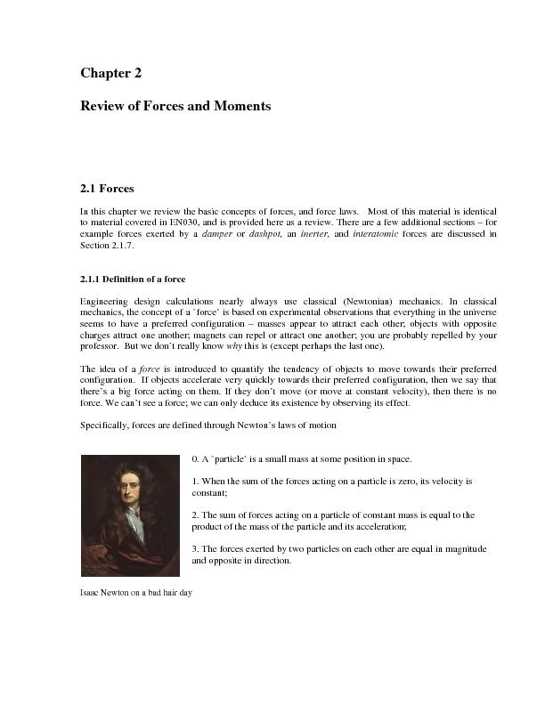
PDF-In this chapter we review the basic concepts of forces, and force laws
Author : phoebe-click | Published Date : 2016-08-27
US units have a frightfully confusing way of representing mass
Presentation Embed Code
Download Presentation
Download Presentation The PPT/PDF document "In this chapter we review the basic conc..." is the property of its rightful owner. Permission is granted to download and print the materials on this website for personal, non-commercial use only, and to display it on your personal computer provided you do not modify the materials and that you retain all copyright notices contained in the materials. By downloading content from our website, you accept the terms of this agreement.
In this chapter we review the basic concepts of forces, and force laws: Transcript
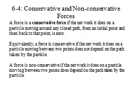
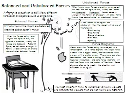
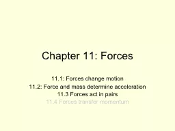
US units have a frightfully confusing way of representing mass. And 57375en 57375ere Were None meets the standard for Range of Reading and Level of Text Complexity for grade 8 Its structure pacing and universal appeal make it an appropriate reading choice for reluctant readers 57375e book also o57373ers students A force is a . conservative force. if the net work it does on a particle moving around any closed path, from an initial point and then back to that point, is zero. . Equivalently, a force is conservative if the net work it does on a particle moving between two points does not depend on the path taken by the particle. . A . force. is a push or a pull. .. Many different forces act on objects around us all the time.. . If . the forces on the object are . balanced. , . then the object doesn’t move. . When two or more forces are acting on an object and they are not equal in size, we say the forces are . 11.1: Forces change motion. 11.2: Force and mass determine acceleration. 11.3 Forces act in pairs. 11.4 Forces transfer momentum. Warm-up Questions (T or F). Speed includes direction, while velocity does not. Forces. Forces can be thought of as pushes and pulls. Examples. You exert a force on a door to open it (a push). Gravity exerts a force on you which holds you to the surface of the earth (a pull). Forces. What is pressure?. Pressure is the force per unit area that is applied on the surface of an object.. Chapter 12: Forces and Fluids. Calculating pressure. Pressure increases if the force applied increases and decreases if the area of contact increases.. . . Example:. What is a force? . a) Strong . nuclear . force. b) Electromagnetic force. c) Weak force. d) Gravity.. EXAMPLE? an atom . #2) There are four forces that hold all matter together. 3) Gravitational forces . The most important chapter of physics EVAR. What is a Force?. A force is a push or a pull. Contact forces:. Boat pulling a water skier. Pushing a car with a dead battery. Noncontact forces:. Gravitational attraction of moon to earth. What is a force?. A force is a push or a pull. . Forces make objects accelerate. What are the two general types of forces? How are they different?. Type 1: Contact Forces. Force as a result of object touching. La gamme de thé MORPHEE vise toute générations recherchant le sommeil paisible tant désiré et non procuré par tout types de médicaments. Essentiellement composé de feuille de morphine, ce thé vous assurera d’un rétablissement digne d’un voyage sur . Forces and Uniform Circular Motion Physics Unit 2 This Slideshow was developed to accompany the textbook OpenStax Physics Available for free at https:// openstaxcollege.org/textbooks/college-physics Force and Motion Basketball Review Game Game Rules If your team gets the question right, you get a chance to shoot the ball into the hoop. If you get the ball in the hoop, each person on your team wins a piece of candy. Forces and Newton’s Laws SP1. Students will analyze the relationships between force, mass, gravity, and the motion of objects. d. Measure and calculate the magnitude of frictional forces and Newton’s three Laws of Motion. . Scalars and vectors. . Types of forces. . Resultant of forces. . Equilibrium of particles. Scalar and Vectors. . Scalar - . a physical quantity that is completely described by a real number.
Download Document
Here is the link to download the presentation.
"In this chapter we review the basic concepts of forces, and force laws"The content belongs to its owner. You may download and print it for personal use, without modification, and keep all copyright notices. By downloading, you agree to these terms.
Related Documents