/
International Conference on Renewable Energies and Power Quality (ICRE International Conference on Renewable Energies and Power Quality (ICRE

International Conference on Renewable Energies and Power Quality (ICRE - PDF document

phoebe-click
phoebe-click . @phoebe-click
Follow
395 views
Uploaded On 2016-10-28

International Conference on Renewable Energies and Power Quality (ICRE - PPT Presentation

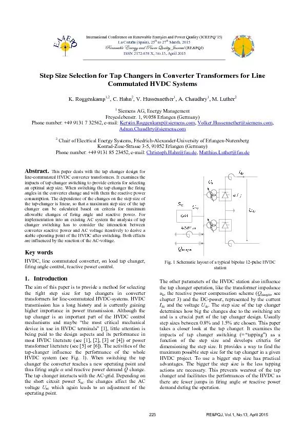
Step Size Selection for Tap Changers in Converter TransfK Roggenkamp12 A Chaudhry M Luther Siemens AG Energy Management Freyeslebenstr 1 91058 Erlangen Germany AdnanChaudhrysiemenscom ID: 481630

Step Size Selection for Tap

Share:

Link:

Embed:

Download Presentation from below link

Download Pdf The PPT/PDF document "International Conference on Renewable En..." is the property of its rightful owner. Permission is granted to download and print the materials on this web site for personal, non-commercial use only, and to display it on your personal computer provided you do not modify the materials and that you retain all copyright notices contained in the materials. By downloading content from our website, you accept the terms of this agreement.


Presentation Transcript

International Conference on Renewable Energies and Power Quality (ICREPQ’15) La Coruña (Spain), 25 March, 2015exÇxãtuÄx XÇxÜzç tÇw cÉãxÜ dâtÄ|àç ]ÉâÜÇtÄ(RE&PQJ) ISSN 2172-038 X, No.13, April 2015 Step Size Selection for Tap Changers in Converter TransfK. Roggenkamp1,2, A. Chaudhry, M. Luther Siemens AG, Energy Management Freyeslebenstr. 1, 91058 Erlangen (Germany) Adnan.Chaudhry@siemens.com Chair of Electrical Energy Systems, Friedrich-Alexander-University of Erlangen-Nuremberg Konrad-Zuse-Strasse 3-5, 91052 Erlangen (Germany) Phone number: +49 9131 85 23452, e-mail: Christoph.Hahn@fau.deMatthias.Luther@fau.de This paper deals with the tap changer design for line-commutated HVDC converter transformers. It examines the impacts of tap changer switching to provide criteria for selecting an optimal step size. When switching the tap changer the firing angles in the converter change and with them the reactive power consumption. The dependence of the changes on the step size of the tap-changer is linear, so that a maximum step size of the tap changer can be calculated based on criteria for maximum allowable changes of firing angle and reactive power. For https://doi.org/10.24084/repqj13.286 223 RE&PQJ, Vol.1, No.13, April 2015 Background: Tap Changers in HVDC The tap changer allows changing the transfer ratio of the converter transformer in order to provide the required valve side voltage at every load point. Thus compensation of voltage drops of the converter or compensation of deviations of the AC voltage from the design value is possible. Tap changers are usually used for angle control and keep firing and extinction angle within a specified band between a maximum and a minimum angle. For the design of the tap changer it is important to know the exact effects of tap changer switching. Due to the tapping the transfer ratio of the transformer changes and the secondary voltage reaches a new value that is dependent on the tap changer position and the step size. With the new valve side voltage comes a new firing angle , where the cosine of the angle is dependent on the secondary voltage. The new firing angle means a new operating point for the converter what goes in line with a new reactive power demand The change in reactive power due to the tapping causes a change in the AC voltage, where the amount of change is dependent on the short circuit power of the AC grid Due to the AC-voltage change a new secondary voltage is derived. This also means a new firing angle and reactive power consumption. The reactive power change again affects the AC-voltage leading to iteration until a stable operating point is reached. The changes become smaller and settle down at a certain value. When determining the impacts due to tap changer switching the change in AC-voltage always has to be considered. It counteracts the effects of the switching. The change of angle and reactive power due to the tapping are directly dependent on the step size of the tap-changer. Angle step and reactive power step can be ect in dependence on the specific project data, like the transferred power, the short-circuit impedance of the transformer, installed equipment for reactive power compensation, AC voltage and the short circuit power of the AC grid (see Fig. 1). The necessary equations for the calculations can be found e.g. in [1], [3] or [4]. If the calculations of the impacts of tapping are done for different currents (i.e. for different DC power), it is figured out that the largest step in the firing angle occurs for low current. This is due to the AC voltage-change that has more influence at high power. The step in the reactive power demand is biggest for high current. Criteria for calculating the maximum step size In order to calculate the maximum step size the dependency of the tapping impacts on the step size has to be determined. Therefore the changes in firing angle and r different step sizes to derive a function that describes the dependencies. The dependencies of the tapping impacts on the step size are calculated at the extreme impact points. This is at low power for the firing angle and at high power for the reactive power demand. From these dependencies the maximum step size can be determined. There are two criteria to setting limits for the angle step and the reactive power step: angle criterion says that the change of the firing angle must not be bigger than the overall angle band, i.e. the difference of maximum and minimum angle. Otherwise tapping would immediately lead to another tapping process in reaction to the first one. This so-called hunting has to be avoided. Therefore the tapping does usually not use the whole angle band to leave some reserve for e.g. voltage deviations. Fig. 2 shows the scheme of angle control for an up-ramp (tap at min) and a down-ramp (tap at max) process. ߂ߙ൑ߙ(1) Fig. 2 Firing angle control scheme Fig. 3 Reactive power control scheme reactive power criterion says that the change of the reactive power demand should not exceed a specified value marginmargin is usually a value for filter switching to cause a hysteresis in the reactive power exchange curves for up- and down-ramping (see Fig. 3). As the reactive power standards must also be complied by the tap-changer, margin is defined as the maximum step in 224 tapping. Thus it is assured that the reactive power exchange stays within the allowed limits and the tapping does not provoke further filter switching. ߂ܳ൑ܳ(2) Calculation Process In order to find the maximum step size the dependencies of angle change and reactive power change on the step size must be calculated. Therefore the changes are calculated for different step sizes to derive a function that describes the dependencies. The dependencies can be calculated as οொή௦௧௘௣௦௧௘௣ and ݉οఈή௦௧௘௣௦௧௘௣ (3) where and are the slopes of the lines that describe the dependencies and are the calculated changes for a specific step size . The functions should be fitted as lines through the origin since a step size of 0% will not derive any changes. From the function ߂ߙൌ݉ήݏݐ݁݌(4) it is possible to calculate the maximum step size that guarantees that the angle step after tapping does not lead to a violation of the angle limits. The angle step can be the difference between maxmin at most. The change in the reactive power demand after tapping should not exceed a specified value margin. From this condition a maximum step size can be calculated from the function ߂ܳൌ݉ήݏݐ݁݌(5) as well. It is important to do the calculations of angle step and reactive power step for realistic tapping-points. Tapping will take place when the firing angle reaches its lower (up-ramp) or upper (down-ramp) limit. Based on this angle the tap changer position and DC-current have to be determined. At this point the tap changer position can be raised (down-ramp) or decreased (up-ramp). The angle step is then calculated as the difference between angle before tapping and angle after tapping (same for the reactive power demand). Here also the impacts of the AC voltage change have to be considered. It is crucial to use a realistic tapping-point as starting-point as the firing angle is calculated through its cosine and a change of the cosine has different impacts on the angle change depending on the angle range, i.e. tapping at 12° will lead to another angle step than tapping at 18°. Only the calculation for tapping at real maximum or minimum angles will derive results that are relevant for the practical operation of the HVDC. There are four cases to consider when calculating the impacts of tapping: up-ramp and down-ramp of the HVDC and rectifier and inverter operation. For the up-ramp tapping takes place at minimum angles min as the angles decrease with increasing current. For the down-ramp the maximum angle max is the limit for the tap changer. The distinction between rectifier and inverter operation is important to take the different DC-voltage at the inverter due to the influence of the DC line resistance into account. Furthermore there are usually different angle limits for the firing angle at the rectifier than for the extinction angle at the inverter. On the one hand this means a different maximum value of angle change following the angle criterion. On the other hand it also directly affects the angle step and reactive power step because a change in the cosine of the angle has different impacts on the angle in different angle ranges. From all cases the total maximum step size can be derived. It is the smallest maximum step size from all examined cases. The functions and equations described in the last two sections were implemented in MATLAB in order to obtain a tool for an automated calculation of the tapping impacts and the maximum step size for a specific HVDC station. For a test of the program the data of a typical bipolar HVDC station (Table I) was used. Table I HVDC parameters for calculation UacN 500 kV IdcN 2000 A N 15° max 17.5° min 13° 18.5° min 18° max 20.5° u k pu SSC , min 7000 MVA 0.002 pu Rdc 5 Filte r max Filte r min mar g in 30 MVar step 0.25% to 2.0% (7 values) From this data the dependencies of the step in the firing angle and the step in the reactive power demand on the step size can be calculated. Calculations were made for the four different cases of rectifier operation, inverter operation and up- and down-ramp. The plotted functions can be seen in Fig. 4 and Fig. 5. The results for the dependencies differ slightly according to the various cases. Part of these differences can be explained by the different currents at the point of tapping. As all calculations are made for realistic tapping points, i.e. for the minimum or maximum angle, the currents may be a little bit higher or lower for one case than for the others. To calculate with identical currents for all cases would not solve this problem, since then the firing angles would differ. Total comparability is not possible. Of course, there is also a systematic difference between the cases. This is due to the different angle ranges 225 in the calculation (higher angles for down-ramp and for inverter operation than for up-ramp and for rectifier operation). However, this systematic difference may not be reflected by the results due to the dominating influence of the chosen operating points. For that reason it is impossible to determine a universal worst case. It is recommended to calculate for realistic tapping points and to consider all cases to find the maximum step size. Fig. 4 Angle change due to tapping Fig. 5 Reactive power change due to tapping The maximum step sizes for the angle and the reactive power criterion for each case are summarized in Table II. The smallest maximum step size is the step size that complies the criteria for all cases. It is 1.82 % for the chosen HVDC station. Table II Maximum step size for the different cases rect, up rect, down inv, up inv, down maximum step size (%) angle criterion 2.90 2.85 2.10 1.82 maximum step size (%) reactive power criterion 2.65 2.67 2.69 2.76 This paper showed a way to determine the step size for the tap changer in the converter transformer for a line-commutated HVDC system. In order to calculate a maximum step size a function has to be derived showing the dependency of the changes in firing angle and reactive power demand on the step size. This is done by calculating the changes for different step sizes and then fitting a line through the values. The results will differ in dependence on the specific project data, like the transferred power, the short-circuit impedance of the transformer, installed equipment for reactive power compensation, AC voltage and the short circuit power of the AC grid. Two criteria must be complied to allow a proper operation of the tap changer in the HVDC system: the change in the firing angle must not exceed the angle band between maximum and minimum angle and the change in reactive power demand must be smaller than the value margin defined for the reactive power exchange. The maximum step size that fulfills these criteria for all cases of operation from rectifier operation in up-ramp to inverter operation in down-ramp is the limiting value in the selection of the step size. References J. Arrillaga, High Voltage Direct Current TransmissionThe Institution of Engineering and Technology, London , London E. W. Kimbark, Direct Current Transmission. John Wiley & Sons, New York, London, Sydney, Toronto, 1971. 971. D. Wilhelm, High-Voltage Direct Current HandbookElectric Power Research Institute, Palo Alto, CA, 1994. . K.-W. Kanngießer, H. Huang, H. P. Lips, N. Christl, G. Wild, D. Retzmann, P. Riedel, K. Sadek, C. Storner und M. Gumbert, HVDC Systems and Their Planning, Siemens, Munich (Germany) 1996. 1996. W. Dietrich, Transformatoren: Stand der Technik und , vde-Verlag, Berlin (Germany) 1986. . J. H. Harlow, Electric power transf, CRC Press LLC, Boca Raton, FL, 2004. 0 1 2 0 1 2 3 Stepsize (%)(°)Angle Change, rect, up = 1.55°/% step Values Fit 0 1 2 0 1 2 3 Stepsize (%)(°)Angle Change, rect, down = 1.58°/% step Values Fit 0 1 2 0 0.5 1 1.5 2 2.5 Stepsize (%)(°)Angle Change, inv, up = 1.19°/% step Values Fit 0 1 2 0 1 2 3 Stepsize (%)(°)Angle Change, inv, down = 1.38°/% step Values Fit 0 1 2 0 5 10 15 20 25 Stepsize (%) (MVar)Reactive Power Change, rect, up = 11.31 MVar/% step Values Fit 0 1 2 0 5 10 15 20 25 Stepsize (%) (MVar)Reactive Power Change, rect, down = 11.23 MVar/% step Values Fit 0 1 2 0 5 10 15 20 25 Stepsize (%) (MVar)Reactive Power Change, inv, up = 11.14 MVar/% step Values Fit 0 1 2 0 5 10 15 20 25 Stepsize (%) (MVar)Reactive Power Change, inv, down = 10.89 MVar/% step Values Fit 226 RE&PQJ, Vol.1, No.13, April 2015 https://doi.org/10.24084/repqj13.286