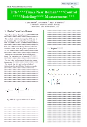
/
Sample Title PageAll of this text should be in Times New Roma�n�gins s Sample Title PageAll of this text should be in Times New Roma�n�gins s

Sample Title PageAll of this text should be in Times New Romangins s - PDF document

phoebe-click
phoebe-click . @phoebe-click
Follow
387 views
Uploaded On 2016-07-07

Sample Title PageAll of this text should be in Times New Romangins s - PPT Presentation

N ational Groundwater Contaminated Land Centre repor t N Environment Agency N ational Groundwater Contaminated Land Centre10 Warwick RoadWest MidlandsWS Atkins Piling and penetrative ground improv ID: 394993

N ational Groundwater Contaminated Land

Share:

Link:

Embed:

Download Presentation from below link

Download Pdf The PPT/PDF document "Sample Title PageAll of this text should..." is the property of its rightful owner. Permission is granted to download and print the materials on this web site for personal, non-commercial use only, and to display it on your personal computer provided you do not modify the materials and that you retain all copyright notices contained in the materials. By downloading content from our website, you accept the terms of this agreement.


Presentation Transcript

Sample Title PageAll of this text should be in Times New Roma&#x-100;n&#x-100;gins should all be set to 30mm&#xMar-;ጀ&#xMar-;ጀPiling and Penetrative Ground ImprovementMethods on Land Affected by Contamination:Guidance on Pollution PreventionF J Westcott, C M B Lean & M L CunninghamMay 2001 N ational Groundwater & Contaminated Land Centre repor t N Environment Agency N ational Groundwater & Contaminated Land Centre10 Warwick RoadWest MidlandsWS Atkins Piling and penetrative ground improvement methods on land affected by contamination:Guidance on pollution prevention.NGWCLC Report NC/99/73Publishing Organisation:(All text in 12 point)Environment AgencyWaterside DriveAztec WestAlmondsburyBristol BS32 4UDTel:01454 624400Fax: 01454 624409©Environment Agency 2001ISBN:1 85705 319 2All rights reserved. No part of this document may be produced, stored in a retrieval system, ortransmitted, in any form or by any means, electronic, mechanical, photocopying, recording orotherwise without the prior permission of the Environment Agency.The views expressed in this document are not necessarily those of the Environment Agency. Itsofficers, servant or agents accept no liability whatsoever for any loss or damage arising fromthe interpretation or use of the information, or reliance upon views contained herein.Dissemination statusInternal:Released to regionsExternal:Released to public domainStatement of useThis report presents initial technical guidance on the potential impact that intrusiveground improvement and piling techniques can have on the environment. It focuses, inparticular, on the potential for pollution of groundwater. The information within thisdocument is for use by Environment Agency staff and others involved in theredevelopment of, and construction on, land that has been affected by contamination.The report may be revised in future as additional research and data becomes available,since it is recognised that the current information base on the effects of piling is limited.Research contractorThis document was produced under National Groundwater & Contaminated LandCentre Project NC/99/73 by:WS AtkinsWS Atkins HouseBirchwood BoulevardWarringtonCheshire, WA3 7WAEnvironment Agencys Project ManagerJonathan Smith, National Groundwater & Contaminated Land CentreThe Agency is grateful for comments on draft reports from: The Federation of PilingSpecialists, The Steel Construction Institute and the School of Civil & StructuralEngineering, University of Sheffield. Piling and penetrative ground improvement methods on land affected by contamination:Guidance on pollution prevention.NGWCLC Report NC/99/73Pollution Scenario: 2Creation of preferential pathways, through a low permeability surface layer, toallow migration of landfill gas, soil gas or contaminant vapours to the surface.Source/Contaminant:Gassing (e.g. methanogenic) landfilled waste or contaminated ground.Pathway:Pile/stone column, pile/soil interface or disturbed ground around pile.Receptor:Description:This situation may be encountered where development is proposed on an old landfill, ora brownfield site when ground levels have been raised using contaminated (gas-generating) fill. Alternatively this may occur where land has been contaminated withvolatile compounds, such as petroleum spirit. Frequently an impermeable cap is presentas part of the remediation solution to manage the existing gassing regime.Disturbance of this capping layer has the potential to create a migration pathway forlandfill gas, or could create air-flow pathways that might render an active gas extractionsystem ineffective. The introduction of air may affect the existing gas generation withinthe fill, for example, increasing the rate of degradation and increase the volume of gasgenerated.Cases of known/inferred pollution or research findings suggesting possibility ofpollution:None reported, however, this cannot be taken as evidence for non-existence of cases. Itis noted that migration of soil gas through stone filled columns is directly comparable tolandfill gas interception trenches that are designed to vent migrating landfill gas toCases where regulatory concern has been expressed:Few cases reported. It is assumed that the severity of the consequences of failure of gasprotection measures are such that designers will normally adopt a precautionaryapproach and design aavoid such an occurrence. Piling and penetrative ground improvement methods on land affected by contamination:Guidance on pollution prevention.NGWCLC Report NC/99/73 Figure 4.2 Pollution scenario 2: vapour migration to surface Piling and penetrative ground improvement methods on land affected by contamination:Guidance on pollution prevention.NGWCLC Report NC/99/73Pollution Scenario: 4Direct contact of the piles or engineered structures with contaminated soil orleachate causing degradation of pile materials.Source/Contaminant:Contaminated soil, waste or leachate.Pathway:Direct contact with pile.Receptor:Built development (and users).Description:ted soil or leachate may be aggressive degradation to the piles,reducing or eliminating their load carrying capacity, and possibly creating migrationpathways.In an extreme case, this could lead to catastrophic failure of building structures,although a building designer and local authority building control officer should beexpected to take into account any aggressive properties of the ground in preparing andapproving their designs.From a purely environmental point of view, the most significant impact could becreated by subsequent remedial works designed to maintain the buildings stability.Cases of known/inferred pollution or research findings suggesting possibility ofNone reported, however, this cannot be taken as evidence for non-existence of cases.Cases where regulatory concern has been expressed:None reported by the Environment Agency, though a number of cases are reportedwhere geotechnical designers or piling specialist contractors have selected particularmethods or taken particular design measures to protect piles from chemical attack.The Environment Agencys interest in this issue is primarily where corrosion of the pilewould subsequently lead to opportunity for pollution migration. Responsibility forassessing the risks to buildings normally lies with the local authority. Piling and penetrative ground improvement methods on land affected by contamination:Guidance on pollution prevention.NGWCLC Report NC/99/73 Figure 4.4 Pollution scenario 4: corrosion of pile leading to creation of flow paths Piling and penetrative ground improvement methods on land affected by contamination:Guidance on pollution prevention.NGWCLC Report NC/99/73Pollution Scenario: 6Contamination of groundwater and, subsequently, surface waters by wet concrete,cement paste or grout.Source/Contaminant:Concrete, cement paste or grout introduced to the ground during piling/penetrativeground improvement operations.Pathway:Flow within highly permeable or fractured strata.Receptor:Groundwater and surface water.Description:Loss of wet concrete, cement paste or grout may occur in fast-flowing groundwater,probably associated with fractured or jointed rocks such as limestones and the Chalk orpermeable gravel formations. Migration may occur until setting of the concrete, cementpaste or grout occurs; this would generally occur on a timescale of a few minutes. Useof retarder additives could extend this timescale to a few hours, although theireffectiveness would be reduced by dilution. In most circumstances, therefore, theimpact, if any, is likely to be localised.Cases of known/inferred pollution or research findings suggesting possibility ofInjection of grouts into mine workings to improve ground stability has resulted inpollution of a nearby river and pond in at least one reported case, as grout migratedthrough the workings and fractures, and subsequently through the bed of thewatercourse.Cases where regulatory concern has been expressed:None reported by the Environment Agency. For geotechnical and economic as well asenvironmental reasons, a piling method which avoids the risk of loss (e.g. use ofpermanent casing or pre-formed piles) would generally be chosen when piling throughhighly fissured or permeable strata. Piling and penetrative ground improvement methods on land affected by contamination:Guidance on pollution prevention.NGWCLC Report NC/99/73 Figure 4.6 Pollution scenario 6: injection of grouts or pastes into groundwater Piling and penetrative ground improvement methods on land affected by contamination:Guidance on pollution prevention.NGWCLC Report NC/99/736.5 The Foundation Works Risk Assessment ReportThe recommended risk assessment process to be carried out by the scheme designer isgiven in Figure 1. It provides a framework for the designer to carry out a riskassessment enabling him to select an appropriate piling or ground improvement methodand justify this choice, with mitigation, if required, and appropriate QA/QC measures.The justification may be presented in the form of a Foundation Works Risk AssessmentSubmission of a Foundation Works Risk Assessment Report will not absolve thedeveloper and his professional and construction team from their duties not to cause orknowingly permit pollution, harm or nuisance. It is expected that the developer willrequire the report to form part of the designers contract obligations. The designer willbe expected to exercise reasonable skill and care in the preparation of the report andmay be held liable, subject to legal action by relevant parties, if this can bedemonstrated not to have occurred.It is envisaged that the issues outlined in Box 6.1 below should be addressed in theFoundation Works Risk Assessment Report in order to present a rigorous andcomprehensive risk assessment. The entire decision-making process should bedescribed in a rigorous and justifiable manner, including a description of any methodsthat were considered and rejected. Foundation Works Risk Assessment Report1.Introduction. An introductory section should describe the site setting in terms ofgeology (including stratigraphic logs), hydrogeology, soil or groundwatercontamination, existence of any landfill, topography, geotechnical considerationsand requirements for piling or ground improvement methods.2.Initial selection of piling method: Justification, on geotechnical, structural andnoise/vibration grounds, of the initially preferred method proposed.3.Identification of potential adverse environmental impacts that may be caused by4.Site-specific assessment of the magnitude and consequences of the identified risksto the environment, workers and residents, both in terms of existing problems and linkages that could be created during site works.5.Identification of any changes to preferred method. Consideration of mitigationmeasures that may be required to prevent pollution, harm or nuisance occurring.6.Identification of QA/QC methods and measures.7.Justification of finally selected methodology, including mitigation, QA/QC andmonitoring measures, with regard to geotechnical, financial and environmental Piling and penetrative ground improvement methods on land affected by contamination:Guidance on pollution prevention.NGWCLC Report NC/99/736.6 Examples of Issues to be Addressed in ReportReference is made to the al problems considered in Chapters 4and 5 of this report for examples of issues to be addressed in the Foundation Works6.6.1 Pollution scenario 1: Creation of preferential pathways, through a lowpermeability layer (an aquitard), to allow potential contamination of an aquifer.Are there polluting substances in the ground that are in a leachable or mobileIs the groundwater directly underneath the site, or in strata penetrated byengineered structures, considered to be in a Major or Minor Aquifer or is thegroundwater in hydraulic continuity with a surface water body?Will the piling or ground improvement method of choice breach a lowpermeability layer (aquitard) or the basal liner of a penetrate an aquifer?Is there a hydraulic gradient that could cause contaminants in near surfacedeposits to migrate into an underlying aquifer or surface water body?Is the pile made out of a material (e.g. timber) that could allow passage ofWill the piling or ground improvement method of choice have the potential tocreate a preferential flowpath for the migration of contaminated perched water orleachate into an aquifer or surface water body?6.6.2 Pollution scenario 2: Creation of preferential pathways, through a lowpermeability surface layer, to allow migration of landfill gas, soil gas orcontaminant vapours to the surface.Is the contamination considered to present a potential source of either landfill gas(for example, waste materials giving rise to methane, sulphur dioxide and carbondioxide) or volatile organic compounds (for example, BTEX volatilising fromhydrocarbon contaminated soils)?Will the piling or ground improvement method of choice have the potential tocreate a preferential flowpath for the migration of gas or vapour to surface?Will the risks arising from accumulation of landfill gas or contaminant vapours inenclosed spaces in the proposed development be mitigated by the incorporationof standard gas protection measures into the building design?Is the release of gases to atmosphere acceptable from an air quality point of6.6.3 Pollution scenario 3: Direct contact of site workers and others with contaminatedsoil arisings, which have been brought to the surface.Are contaminants present in the soil or groundwater at sufficient concentrationsto pose a hazard to human health or the environment? Piling and penetrative ground improvement methods on land affected by contamination:Guidance on pollution prevention.NGWCLC Report NC/99/73Will the piling or ground improvement method of choice have the potential tobring potentially contaminated soil arisings to the surface?Are measures in place to contain and dispose of arisings in a safe manner?6.6.4 Pollutant scenario 4: Direct contact of the piles or engineered structures withcontaminated soil or leachate causing degradation of pile materials.Does the nature of the soil or leachate contamination present a risk to theperformance or durability of the pile material?6.6.5 Pollutant scenario 5: The driving of solid contaduring pile driving.Are there polluting substances in the ground that are in a leachable or mobileIs the groundwater directly underneath the site, or in strata penetrated byengineered structures, considered to be in a Major or Minor Aquifer or is thegroundwater in hydraulic continuity with a surface water body?Will the piling or ground improvement method of choice breach a lowpermeability layer (aquitard) or the basal liner of a closed landfill site orpenetrate an aquifer?Does the chosen piling method involve use of blunt-ended solid or closed-endpiles that could drag down soil or open-ended tubular piles that could becomeplugged with soil?6.6.6 Pollutant scenario 6: Contamination of groundwater and, subsequently, surfacewaters by concrete, cement paste or grout.Does the chosen piling or penetrative ground improvement method involve theintroduction of wet concrete, cement paste or grout into the ground?Is the groundwater directly underneath the site, or in strata penetrated byengineered structures, considered to be in a Major or Minor Aquifer or is thegroundwater in hydraulic continuity with a surface water body?Is the aquifer characterised by highly fissured or granular strata?Is the groundwater in the aquifer fast-flowing?6.7 Procedure for Presentation of ReportIt is envisaged that any requirement for a Foundation Works Risk Assessment willnormally be enforced through the planning system. The Environment Agency, as aconsultee on planning application matters affecting contaminated land would normally,by means of its consultation response, seek to have the planning authority place relevantconditions on the planning permission. Such conditions might be to the effect that nopiling, ground improvement or building construction shall take place until a Foundationsubmitted to the planning authority and itsdetail and recommendations accepted by the planning authority in consultation with theEnvironment Agency. Piling and penetrative ground improvement methods on land affected by contamination:Guidance on pollution prevention.NGWCLC Report NC/99/73The procedure for the consideration of the Foundation Works Risk Assessment reportwould be similar to that by which the regulatory authorities proposals as part of planning applications. This is likely to involve dialogue between thedeveloper and his professional advisers, the Environment Agency and the PlanningAuthority. As with any works that could adversely affect the environment, informaldiscussions between all parties prior to submitting planning applications areprudent.Following acceptance by the relevant authorities it will be necessary, prior tocommencing works on site, for the designer to ensure that any proposed mitigation andQA/QC measures are fully designed, specified and actually implemented on site. Piling and penetrative ground improvement methods on land affected by contamination:Guidance on pollution prevention.NGWCLC Report NC/99/73 Piling and penetrative ground improvement methods on land affected by contamination:Guidance on pollution prevention.NGWCLC Report NC/99/737. RECOMMENDATIONS FOR FURTHER RESEARCH of adverse environmental impacts caused by piling orpenetrative ground improvement works is one that has largely been neglected in theresearch arena. As a result it has not been possible in all the scenarios considered todetermine unequivocally the significance of the risks to the identified receptors thatmight arise from piling. In these cases it is apparent that there would be benefit fromfurther research into the pile and surrounding soil behaviour in the individual cases.The research may take a number of forms:Documentation and recording of site based case studies;Computationally based numerical modelling, possibly using existing test data fromprevious structural research;Scale model testing, though Hayman (1993) observe that scaling ofhydrogeological systems is extremely difficult;Full scale trial pile installation and monitoring;Retrospective investigation of sites where piles have been used in the past;Detailed instrumentation and monitoring of developments involving piling onThere is a considerable cost implication to some of these options and it is likely to benecessary to adopt a staged approach to this research, using less expensive approachesto identify any particularly difficult issues that may require more detailed consideration.One approach may be to carry out comparative studies between different pile types,though it is expected that the key comparison will be with the soil in its undisturbedstate. Research into the effectiveness of mitigation measures could be based oncomparison with the unmitigated case.One of the key areas of uncertainty identified in this study is the impact of displacementpiling on aquitard strata or low permeability cover layers. Whilst a concern haspreviously been identified that the action of pile driving could serve to disrupt andincrease the permeability of the aquitard layer, consideration of the densification of thesoil caused by displacement tends to indicate a reduction in permeability in theimmediate vicinity of the pile. It is likely that the effect on a thick aquitard layer will bedifferent from the effect on a thin layer and the research should consider both cases.Both permeability to water (including leachate) and gas permeability should beResearch should consider in particular the effect of displacement piling on stiffoverconsolidated clayey soils such as are commonly encountered in glacial tills. Thephenomenon of frictional drag down of soils in contact with the circumference of thepile shaft should be examined to determine the effect on the vertical permeability of the Piling and penetrative ground improvement methods on land affected by contamination:Guidance on pollution prevention.NGWCLC Report NC/99/73soil. The particular case of the impact of driven piles such as steel H-piles with a re-entrant cross section on an aquitard layer should be considered.The behaviour of the soil at the interface with a non-displacement pile should also beexamined for the range of non-displacement pile types and casing systems. As thenature of the soil interface is likely to be determined to a large degree by the method oftemporary support and permanent installation it is likely that such research may need tobe based on full scale testing or monitoring.Research into non-displacement piling systems should also examine the risks oftransmission of groundwater through the bored hole in the temporary case prior to thecasting of concrete, and taking into consideration the effect of construction measuressuch as the maintenance of a positive hydrostatic head in the borehole duringA further development of the research might involve the determination of quantitativemeasures, for example, if increased flow rates of leachate due to the impact of pilingwere measured. Theseused as the basis for riskmodelling using contaminant fate, transport and attenuation modelling Piling and penetrative ground improvement methods on land affected by contamination:Guidance on pollution prevention.NGWCLC Report NC/99/738.REFERENCESBarry, D. (1983). . Construction IndustryResearch and Information Association Report 98, CIRIA Publications. London.Boutwell, G.P., Nataraj, M.S. and McManis, K.L. (2000). Deep Foundations onBrownfields Sites. PRAGUE 2000 Conference, Prague.Building Research Establishment (1986). , BREDigest 315.BRE (1996). Sulphate and Acid Resistance of Concrete in the Ground, BRE Digest 363.Campbell, P.L., Bost, R.C. and Jacobsen, R.W. (1984). Subsurface Organic Recoveryand Contaminant Migration Simulation National Symposium on AquiferRestoration and Groundwater Monitoring, Columbus.Construction Industry Research and Information Association (1988). , CIRIA PSA Engineering Technical Guide 5.CIRIA (1995). Remedial Treatment for Contaminated Land, CIRIA Special PublicationCIRIA (1999). . CIRIA reportC 510. London.Department of the Environment (1994). A Framework for Assessing the Impact ofContaminated Land on Groundwater and Surface Water, CLR No. 1, Volumes 1 and 2,prepared by Aspinwall and Company.Department of the Environment (1995). Department of the Environment, Transport and the Regions (1999). . DETR Circular 2/99.Statutory Guidance on The Contaminated Land (England) RegulationsDETR, Environment Agency & Institute for Environment and Health (2000).Guidelines for Environmental Risk Assessment and Management. The Stationery Office.DoE & CIRIA Piling Group (1977). The Use and Influence of Bentonite in Bored Pile Piling and penetrative ground improvement methods on land affected by contamination:Guidance on pollution prevention.NGWCLC Report NC/99/73DoE & CIRIA Piling Group (1978). Piling in Boulder Clays and other Glacial TillsPSA Civil Engineering Technical Guide 23.DoE & CIRIA Piling Group (1980). Survey of Problems Associated with the Installation. PSA Civil Engineering Technical Guide 26.DoE & CIRIA Piling Group (1988). A Review of Bearing Pile Types Edition. PSACivil Engineering Technical Guide 5.Environment Agency (1996). . Internal guidanceEnvironment Agency (1998). Policy & Practice for the Protection of GroundwaterStationery Office.Environment Agency (1999). Methodology for the derivation of remedial targets for. R&D Publication 20.Environment Agency (2000a). Risks of contaminated land to buildings, buildingmaterials and services: A literature review. R&D Technical Report P331.Environment Agency (2000b). Introducing Environmental Risk Assessment. NationalCentre for Risk Analysis and Options Appraisal.Environment Agency (2000c). Guidance for the safe development of housing on land. R&D Publication 66. The Stationery Office.Federation of Piling Specialists (March 2000). Deep Foundations and Aquifers, Water& Sewerage JournalFleming, W.G.K. Weltman, A.J. Randolph, M.F. & Elson, W.K. (1992) Edition. Blackie A&P.Fuller, F.M. (1983). Engineering of Pile InstallationsGarvin, S.L. & Ridal, J.P. (2000). Risk Assessment for Building Materials in, CONSOIL 2000 Conference, Leipzig.Hayman, J.W., Adams, R.B. and Adams, R.G. (1993). Conduit for DNAPL Migration. Proc. Air & Waste Management Association Meeting,Paper CM/200. London.Planning Policy Guidance: Planning and Pollution Control, PPG 23. Piling and penetrative ground improvement methods on land affected by contamination:Guidance on pollution prevention.NGWCLC Report NC/99/73Environmental Protection, The Special Waste RegulationsStatutory Instruments no. 972.The Town and Country Planning (Environmental Impact Assessment)(England and Wales) Regulations 1999, SI 1999 no. 293.The Contaminated Land (England) Regulations 2000, SI 2000 no. 227.International Standards Organisation (2000). Water quality … Sampling … Part 18:. ISO 5667-18.Johnson, K. (1995). Steel Piling in Contaminated LandAugust 1995.Keller Ground Engineering (2000). Vibro Ground Improvement Systems. TechnicalLeach & Goodger (1991). , Construction Industry Researchand Information Association Special Publication 78.Matheson, N.C. & Wain, D.E. (1989). Methods of Constructing Piles on Heavily. Proceedings of the 3 International Conference of Piling and deepFoundations. London. AA Balkema: Rotterdam.Performance of Building Materials on Contaminated Land, BuildingResearch Establishment Report 255.Prakash, S. & Sharma, H.D. (1990). , JohnWiley & Sons, Inc.Steel Construction Institute (2001). Communication between Tony Biddle on behalf ofSCI and Candida Lean of WS Atkins.Tomlinson, M.J. (1994). Edition. E & FNWest, A.S. (1972.) , Butterworths.Whittaker, T. (1970). . Pergamon Press. Piling and penetrative ground improvement methods on land affected by contamination:Guidance on pollution prevention.NGWCLC Report NC/99/73 Piling and penetrative ground improvement methods on land affected by contamination:Guidance on pollution prevention.NGWCLC Report NC/99/73AQUIFER A permeable geological stratum or formation thatis capable of both storing and transmitting water insignificant amounts.AQUITARDA low permeability unit that can storegroundwater and also transmit it slowly from oneaquifer to another.AUGERHand or mechanical equipment used to extract soilby method of a drilling motion.BROWNFIELDAbandoned, idle or underutilised industrial orcommercial facilities where expansion orredevelopment is complicated by real or perceivedenvironmental contaminationCASING Steel tube driven into the pile borehole totemporarily support the sides of the bore, it isremoved during the concreting operation.COMPETENT STRATASoil of high bearing capacity.CONTAMINANTA substance which is in, on or under the landcause harm or to causeCONTAMINANT FATEThe combined effects of chemical, biological andphysical processes on a pollutant in theCRAWLERTracked construction vehicle (e.g. crane or dozer).Piling rigs are often 'crawler-mounted' as thismeans that the heavy equipment is spread over awide area meaning that it can safely stand on thesoft ground.DYNAMIC LOADINGRepeated or cyclic loading imposed on a pile, forexample by machinery, traffic or wind.GROUND IMPROVEMENT The improvement of soil properties near thesurface enabling the use of shallow foundationswhere otherwise they would not have beensuitable. Piling and penetrative ground improvement methods on land affected by contamination:Guidance on pollution prevention.NGWCLC Report NC/99/73GROUNDWATERThe mass of water in the ground below the watertable (vadose zone) occupying the total pore spacein the rock and moving slowly down the hydraulicgradient where permeability allows.GROUNDWATER PROTECTION An area designated around a groundwaterZONE (GPZ) source, the maximum extent of which is thecatchment area for the source and within whichthere are limits to the processes and activities thatcan occur within that area.HYDRAULIC CONDUCTIVITYA coefficient of proportionality describing the rateat which water can move through a permeablemedium. The density and kinematic viscosity ofthe water must be considered in determininghydraulic conductivity.KELLY or TORSION BARThe sliding shaft on a boring rig that transmits thetorque to the boring tool from a driven rotarytable.LEACHATEThe liquid that has percolated through solidmaterials and contains dissolved solubleMANDREL A cylindrical rod round which metal or othermaterial is forged or shaped.NECKINGThinning of the pile where the concrete has notcompletely filled the pre-formed shaft.PATHWAYThe route or means by or through which a receptoris being, or could be, exposed to, or affected by, acontaminant.PERMEABILITYMeasure of the ability of a permeable medium totransmit water. It is defined as the volume of waterpassing through 1m of aquifer under unithydraulic gradient.PILE Long, slender structural member, used to transmitloads applied at its top to the ground at lowerPLASTIC CONCRETEConcrete that has yet to set and, whilst may not befully fluid, is still malleable. Piling and penetrative ground improvement methods on land affected by contamination:Guidance on pollution prevention.NGWCLC Report NC/99/73POKER or SONDE Vibrating rod, used to push trapped air fromsetting concrete.S-P-R LINKAGEThe relationship between a source, a pathway anda receptor. (cf. Pollutant linkage under EPA90,Part IIA).PRE-STRESSED CONCRETE Concrete incorporating pre-stressed reinforcementRAFT FOUNDATIONRaft foundations are foundations that cover largeareas laterally, greatly reducing differentialsettlement.RECEPTOR or TARGETA particular entity, which is being or could beharmed by a pollutant, or controlled waters whichare being or are likely to be polluted.REINFORCED CONCRETE Concrete that is strengthened by an internal steelframeSHOE A metal plate that is cast onto the toe of concretepiles whether driven in hard or soft conditions.SPALLING Flaking of the concrete surface.STATIC LOADINGThe load applied to a pile in its normal service life.Usually split into 'dead', i.e. the weight that isalways applied due to the weight of the structure,and 'live', i.e. the loading due to moveable objects(e.g. vehicles, people and furniture).TACK WELDA weld temporarily holding something togetherthat can be broken easily.TORSIONAL LOADINGThe load applied to a pile by imposing a momenton it, i.e. a twisting force in either direction.TREMIE PIPE A pipe that is made up from a number of lengthsof 200 … 300mm diameter steel pipes, which isused to place concrete underwater or at depth.WHIPPINGThe lateral movement of a pile as it is being Piling and penetrative ground improvement methods on land affected by contamination:Guidance on pollution prevention.NGWCLC Report NC/99/73APPENDIX 1SUMMARY OF REPLIES TO QUESTIONNAIREA1.1 Piling and Ground Improvement Contractors who Responded to theQuestionnaireAarsleff PilingAmec PilingKeller Ground EngineeringMay Gurney LimitedNorwest Holst Soil Engineering LimitedRoger BullivantRock & Alluvium LimitedStent Foundations LimitedTaranto De PolThe Expanded Piling Company LimitedWestpile LimitedA1.2 Methods of Piling and Penetrative Ground Improvement Available FromRespondentsDriven cast-in-place pilesBored cast-in-place replacement pilesDriven pre cast pilesDriven cased pilesRotary bored replacement pilesContinuous flight auger pilesDisplacement flight auger pilesPre-cast reinforced concrete pilesSteel sheet pilesTripod bored piles using cable percussive methodsLime / cement columnsVibro stone columns … dry top feed…dry bottom feed…wet top feed Piling and penetrative ground improvement methods on land affected by contamination:Guidance on pollution prevention.NGWCLC Report NC/99/73A1.3 Details Of Sites/Projects in which the Contractor Has Been Involved or AreAware Where the Actual Installation of Piling Has Been Implicated in theMigration of Contaminated Water or Ground/Landfill GasNo information supplied by any contractor.A1.4 Details of Sites/Projects in Which the Contractor Has Been Involved or AreAware Where the Proposed Installation of Piling Has Raised Concerns Over theMigration of Contaminated Water or Ground/Landfill Gas with Planning,Building Control or Environmental RegulatorsAt a large number of sites in southern England, there has been concern over theeffect of piles penetrating the Chalk. In these cases, the Environment Agency hasgenerally preferred continuous flight auger piles over, for example, driven pre-castconcrete piles. Continuous flight auger piles are generally specified in order toreduce the possibility of transporting contaminated soil from the upper layers intothe aquifer and because they do not provide an easy contamination path for surfacewater to reach the lower strata.At a site in the north of England, the National Rivers Authority (one of theAgencys predecessors) had reservations about migration of contaminants into thesandstone due to piling. Initially the piling was priced on the basis of a double-casingŽ method. On agreement that the risks from conventional construction werelow, the double casingŽ method was kept as insurance in the event that particularlyhighly contaminated areas were encountered. The water level and quality weremonitored during piling operations and no significant effect from the piling workAt a site where fill materials lay directly either over chalk or over stiff clays abovethe Chalk, the Environment Agency were concerned at contaminants migrating intothe Chalk aquifer. There was evidence of solution features within the Chalk surface.After further investigation, the Environment Agency reduced their concern, and thesolution features were treated by compaction grouting.At a site in southern England, the use of driven pre-cast concrete piles was notpermitted for fear of taking contamination down into the underlying chalk aquiferand creating groundwater migration pathways. The use of continuous flight augerpiles was acceptable to the Environment Agency, but would have had thedisadvantage of creating significant quantities of contaminated spoil. For thesesimple commercial reasons, the use of a continuous helical displacement system waschosen at this site as it produces virtually no spoil and was not thought likely to takecontamination into the underlying aquifer. This method also reduces thepermeability of strata in the immediate vicinity of the pile and produces no obviouspollution pathways for water to migrate into the lower strata. Piling and penetrative ground improvement methods on land affected by contamination:Guidance on pollution prevention.NGWCLC Report NC/99/73At a site where a former landfill site was underlain by a variable thickness ofboulder clay overlying the chalk aquifer, the preferred option for construction wouldhave involved piling due to the potential for long-term compaction of the landfill.However, due to fears of allowing contaminated landfill leachate to reach theaquifer, a method combining dynamic compaction with the use of very heavyfoundations was adopted. Measures were put in place to monitor and intercept anypossible lateral migration of contaminated leachate during and subsequent to thedynamic compaction operation.At a contaminated site where driven cast-in-situ piles were to be used, concernswere raised about high groundwater levels and the proximity of the site to a nearbywatercourse. A solution involving installation of an HDPE membrane withmonitoring facilities was instigated. Monitoring confirmed that no rise ingroundwater level or deterioration of stream quality had occurred during operations.removed to a specially licensed tip.perceived as offering a pathway for thedownwards migration of leachate. At a number of sites where this has proved causefor concern, either a concrete plug at the base of stone columns formed with the drytop-feed technique or the grouting of stone columns formed using bottom-feedconstruction has been used to inhibit leachate migration.The matter of downward migration was brought to the attention of the EnvironmentAgency on a site in the south of England. The Environment Agency were concernedwith the potential for piling to allow migration of contaminated groundwater froman upper aquifer into an underlying aquifer that was separated from thecontaminants by a clay aquiclude. Following discussions, it was decided that theclay would form a seal around the pile to prevent downward contamination.Furthermore, the size of the pile was increased in order to reduce penetration intothe clay.Common methods of overcoming concerns with regard to piling througha)Designing the piles to stop short of an aquifer.b)Removing contaminated ground from pile positions by bulk excavation andreplacing with clean fill.c)Removal of contaminated ground by pre-boring with the piling rig and casing orfilling the casing with bentonite prior to its removal in piling operation.d)Citing the flow of soil up and away from augers and the seal around bored pilesin order to overcome fears of migration of contamination (most common meansof overcoming concerns according to one respondent).e)Use of bored displacement piles.f)Installation of a mix in place impermeable barrier with permeable active gateto filter contaminants from groundwater leaving the site. Piling and penetrative ground improvement methods on land affected by contamination:Guidance on pollution prevention.NGWCLC Report NC/99/73A1.5 Details of Any Issues Concerning the Disposal of Contaminated Soil Arisingsfrom Replacement Piling that the Contractor May Have Encountered onParticular Sites/ProjectsWhere spoil is classified as special waste, disposal is usually undertaken by aspecialist sub-contractor.Specialist piling contractors may consider that disposal of can issue related to the piling operation. Main contractors are generally responsiblefor the clearance of spoil arisings.Where contamination is present, waste is classified and may require disposal tolicensed tip relevant to classification.Disposal of spoil containing even relatively low levels of contamination can havesignificant cost implications.There is a Health and Safety risk to other road users when there are a large numberof trucks travelling to licensed landfills.There are concerns with regard to the effective sealing of tipper lorry tail-gates onwet days and when spoil is wet, giving rise to the potential for spread ofBentonite contaminated spoil is deemed to be contaminated, although it is a non-toxic natural clay unlike industrial waste. Contractors may consider it messy ratherA1.6 Details of any Material Durability Issues that the Contractor May HaveEncountered When Considering the Design and Specification of Piles in Contactwith Aggressive Contaminated GroundA major concern is the high sulphate content and low pH values in contaminatedsoils. BRE Digest 363 provides guidelines that are universally used.Corrosion of steel joints in pre-cast piles may also be an issue.The presence of phenols may affect the setting and strength of concrete and slurries.Sleeving of piles is sometimes specified, however, one respondent queried thatOne contractor reported the results of trials on the site of a former tank farm that hada long-term history of hydrocarbon contamination. Tests on slurry mixes wereundertaken. When contaminant was mixed directly with slurry, the slurry strengthwas halved. To combat the effect, the cement content of the slurry was increased. Piling and penetrative ground improvement methods on land affected by contamination:Guidance on pollution prevention.NGWCLC Report NC/99/73Occasional instances of concern with regard to contact with other contaminants havebeen recorded, for example sugar contamination.Extreme conditions may require the use of permanently cased piles to preventIn some cases specific protection can be achieved by coating or painting the pilewith proprietary products to provide the necessary protection level.A1.7 Other Information Supplied that is Considered of Relevance to the StudyThere is a lack of information / guidance relating to piling on contaminated sites andthe whole subject area appears to be very much in its infancy. One respondent notedthat 70% of their work is undertaken without any formal site investigation other thanbasic trial pits.Most concerns regarding the pile as a conduit for downward migration ofcontamination ignore the action of the auger, and the densification and/or voidfilling characteristics of displacement auger and continuous flight auger piles. Alsoignored is the short construction period for the piles. Unless the auger is bored inand left stationary whilst large volumes of surface water flow down it, dissolving way, little migration is possible at all.Prior to piling, the site has often been subject to small diameter site investigationboreholes. The site investigation stage can be a cause of cross contamination and iscontrols as the piling operations.The main risk to aquifers probably badly backfilled boreholes rather than piles. Piling and penetrative ground improvement methods on land affected by contamination:Guidance on pollution prevention.NGWCLC Report NC/99/73 Piling and penetrative ground improvement methods on land affected by contamination:Guidance on pollution prevention.NGWCLC Report NC/99/73APPENDIX 2: CASE STUDY EXAMPLES5.CASE STUDY 1: PILING DESIGN FOR RESIDENTIAL DEVELOPMENT ONFORMER INDUSTRIAL SITE. Description of site and proposed development:A residential development was proposed for a former industrial site in the south of England.Piled foundation was required to support the structural loads from the proposed buildings,which were to be 5 to 7 storeys high.Site investigation revealed elevated concentrations of a range of contaminants in the madeground which were considered to pose a risk to the integrity of underground structures.Landfill gas was also considered to represent a potential hazard. Stratigraphy: 1m bgl Ground surface Gravel Sand Clay Made Ground: sandy claywith flint, concrete andbrick gravel Sand Clay Sand Sand Limestone 6.5m bgl 7.5m bgl 13.5m bgl 18.5m bgl 16m bgl 17.75m bgl 19m bglLocal hydrogeology and environmental setting:The stratigraphic sequence present at the site is shown andcomprises about a metre of made ground, consisting of sandyclay with occasional flint, brick and concrete, overlying over5m thickness of alluvial clay. Underlying the alluvium wereapproximately 6m of dense sands and gravels (River Graveldeposits) and, underlying these, a stiff silty clay with densesilty sands comprising the Woolwich and Reading Beds.The alluvial clay may be considered to be an aquiclude, whilethe Woolwich and Reading Beds have variable permeability.The River Gravel deposits are considered to be a MinorAquifer. Underlying the site, below the Woolwich andReading Beds, is the Upper Chalk, which is considered to bea Major Aquifer. A review of piling options concluded that driven cast-in-situ piles because the direct contact with the ground and uneven surface of the pile would give fulladhesion of the clay to the shaft. It had been known that the Environment Agency hadpreferred use of this method on adjacent sites to minimise the risk of groundwatercontamination to deeper aquifers. Also, the amount of contaminated spoil generated isminimised by the use of driven cast-in-situ piles. The pile was to be installed by driving aheavy gauge steel tube into the stratum of gravel until a set was obtained. High slumpconcrete was then placed and the tube withdrawn. The piles were to be founded in the gravel.Gas protection measures were recommended for incorporation in the buildings in order tomitigate the effects of migration of landfill gas. The risk that the piles would form migrationpathways for gases could therefore be discounted.Area-specific assessments of concrete specification were required to protect the piles fromdegradation to take into account sulphate, pH and ammonium ion aggressivity. Piling and penetrative ground improvement methods on land affected by contamination:Guidance on pollution prevention.NGWCLC Report NC/99/736.CASE STUDY 2: PILING DESIGN FOR WASTE WATER TREATMENTWORKS Description of site and proposed development:A waste-water treatment works was constructed on a former industrial site in the south ofEngland. Site investigation revealed elevated concentrations of several toxic metals,including arsenic and selenium, within the soil. Elevated concentrations of severalphytotoxic metals, which are deemed non-hazardous to human health, were also recorded.Methane gas was also recorded in the landfill material at concentrations in excess of thelower explosive limit of 5% volume. Stratigraphy: 3m bgl Ground surface Stiff fissured Clay Stiff Clay Soft Clay Made Ground Lignite Chalk 10m bgl 12m bgl 13m bgl 16mbgl 19m bgl Stiff fissured ClayLocal hydrogeology and environmental setting:The stratigraphic sequence present at the site is shownopposite. Made ground beneath tidal storage tanks on the siteconsisted of 1-1.5m of PFA sand. Below this a 0.5-1.0mthick grey-brown mottled clay with sand and fragments ofglass, brick and flint was present. An organic, potentiallyhydrocarbon, odour was noted in this horizon.The made ground was underlain by alluvium comprising verysoft light grey/green clay. Plant remains were observed at upto 10m depth in this material and an organic odour was noted.The alluvium was underlain by a stiff organic claycomprising the Woolwich and Reading Beds. The alluvialclay and the Woolwich and Reading Beds may be consideredto comprise aquicludes. The site is underlain by Chalk at adepth of approximately 19 mbgl. The Chalk is considered tobe a Major Aquifer. Suggested piling methods involved piles to be founded in the Chalk. It was highlighted thatpiling may raise concern with the Environment Agency as the Chalk is a major aquifer andas providing a potential pathway. It was suggested that pilingcould be carried out using similar protection measures as British Drilling Associationrecommendations for borehole operations. However, this would significantly increase thecost of the piling work.Continuous flight auger piles were recommended to give the best option for reducing anypotential cross contamination. Care was taken to ensure that water and concrete pressureswere balanced in order to minimise concrete losses in all permeable horizons (the gravels andTypical methods of gas protection were to include a gas proof membrane in the base slabstogether with a passive venting layer below. Careful detailing of services connections tobuildings was necessary to avoid the creation of gas pathways. Piling and penetrative ground improvement methods on land affected by contamination:Guidance on pollution prevention.NGWCLC Report NC/99/739.CASE STUDY 5: PILING DESIGN FOR A FACTORY DEVELOPMENT ON AFORMER INDUSTRIAL SITE Description of site and proposed development:Piles were required for a factory development in southern England. Pile working loadsvaried from 200kN to 875kN. Made ground on the site contained elevated concentrations ofa range of organic and inorganic contaminants.Site investigation revealed elevated concentrations of arsenic, lead, boron, copper, zinc,selenium, zinc, phenols and petroleum hydrocarbons within the made ground. Elevatedcarbon dioxide concentrations were also recorded. Stratigraphy: 1.5m bgl Ground surface Sand /Gravel Clay Alluvium Made Ground 4.2m bgl 9m bgl Local hydrogeology and environmental setting:The stratigraphic sequence found at the site is summarisedopposite. Made ground was encountered at the site to a depthof 1.50m and typically comprised sandy clay with a little tosome flint and brick gravel. The made ground also containedconcrete and brick cobbles, ash and wood fragments andAlluvium was present below the made ground, comprising avariable sequence of clay, peaty clay and peat. The peatoften had a hydrogen sulphide odour. Flood Plain Gravelwas encountered below the alluvium and, underlying thegravel, was the London Clay.Groundwater was encountered at the top of the Flood Plain It was recommended that continuous flight auger piles of nominal 300mm and 400mmdiameter were used, founded in the London Clay. Continuous flight auger piles wererecommended due to concerns that contaminated soil might be transported from the upperlayers into an aquifer and because they do not provide an easy contamination path for waterfrom the surface to the lower strata.Due to high concentrations of carbon dioxide recorded, gas protection measures wererecommended, comprising passive venting of the under floor void and the incorporation of agas impermeable membrane into the floor slab design. Piling and penetrative ground improvement methods on land affected by contamination:Guidance on pollution prevention.NGWCLC Report NC/99/7311.CASE STUDY 7: PILING DESIGN FOR HEAVY INDUSTRIAL STRUCTURESON A CLOSED LANDFILL SITE Description of site and proposed development:A closed landfill site in the north of England, occupying a former sand pit, was to bedeveloped for industrial use. The proposed development of heavy industrial structuresrequired the use of large diameter bored piles founded into the sandstone.The site had undergone limited remediation, but localised hot spots of heavy metal andhydrocarbon contamination were present. Stratigraphy: Clay capMunicipal wasteSoft claySands and gravelsSandstone Ground surface 4mbgl7mbgl Local hydrogeology and environmental setting:A schematic stratigraphic sequence is shown opposite.Typical soil conditions comprise 3-4 metres of fillmaterial overlying 3m of soft (alluvial) clay over sandsand gravels. Underlying the sands and gravels is theThe Sherwood Sandstone is considered to be a MajorAquifer in the vicinity of the site. The National Rivers Authority (now incorporated within the Environment Agency) initiallyexpressed major reservations about migration of contaminants into the sandstone due topiling. The Sherwood Sandstone in the north-west of England is classified as a major aquiferwhich is widely used for industrial and potable water abstraction. However, after discussionsit was decided that the risks from conventional construction were low and thereforeconventional piling methods were used. Double casing methods were to be used as acontingency in the event that hot spots were encountered. Visual inspection of arisings tookplace. During piling operations, groundwater level and quality were monitored at threeborehole locations. No measurable effect from the piling work was noted. Piling and penetrative ground improvement methods on land affected by contamination:Guidance on pollution prevention.NGWCLC Report NC/99/7313.CASE STUDY 9: INDUSTRIAL DEVELOPMENT ON A CLOSED DOMESTICLANDFILL SITE Description of site and proposed development:It was proposed to redevelop a closed municipal landfill site in northern England for lightindustrial uses, comprising a number of industrial units and hard paved areas for vehicleparking and loading.Leachate and gas monitoring undertaken in and around the landfill for regulatory purposesduring its operational life, and additional site investigation undertaken in preparation for theredevelopment confirmed the presence of typical landfill pollutants, which were present assolid materials, leachate and gas. The landfill was originally developed on a dilute anddisperse basis, resting on a thick sequence of boulder clay. Following completion oflandfilling the site was capped with a mineral liner to reduce the potential for generation offurther leachate. Investigations indicated that pollutants present in the waste were in aleachable form and that restricted (perched) bodies of landfill leachate were present withinthe body of the waste, however, there was no significant head of leachate at the base of thesite. Groundwater monitoring in the Triassic Sandstone indicated that leachate had notimpacted groundwater quality in the underlying aquifer, and it was inferred that attenuationof leachate within the boulder clay prevented migration into the aquifer. Stratigraphy:Local hydrogeology and environmental setting:A schematic stratigraphic sequence is shownopposite and comprises a metre of clay over 5metres of domestic waste materials. The landfill isfounded on 7 metres of boulder clay, which overliesthe Permo-Triassic Sherwood Sandstone, a majorThe aquifer is not used locally for potable supply atthe current time, but groundwater discharges asbaseflow into a high quality river that supports asalmon fishery.Groundwater monitoring indicates that the TriassicSandstone is currently unpolluted by the landfill,and that groundwater levels are typically 5 to 7metres below the base of the boulder clay. 50m AOD 43m AOD Ground surface,56m AOD Sherwood Sandstone Boulder clay Municipal Waste 38m AOD Sandstone groundwater peizometric surface Legend Engineered clay cap Piling and penetrative ground improvement methods on land affected by contamination:Guidance on pollution prevention.NGWCLC Report NC/99/73and hammer are raised and more concrete is added. The concrete is then driven out bythe hammer hitting the mandrel, as the outer casing is raised. This way a bulb is formedbetween the detached shoe and the pile shaft. Full length reinforcing is usually attachedto the shoe prior to driving (CIRIA, 1988).The finished pile is a continuous solid concrete column with or without reinforcement.The surface of the pile if the tube has been retrieved may vary in roughness dependingon the nature of the surrounding material. The base of the pile may be enlarged toprovide greater stability at the base of the pile.Another variant on the driven cast-in-place pile is the expanded pile. Driven expandedpiles typically have a cruciform cross section (other forms are used) with an examplebeing the Burland wedge pile. A closed sleeve with four steel angle sections is driven.A mandrel is then forced down the sleeve splitting the tack welds giving an expansionof about 10% and increasing the shaft friction (Fleming ., 1992). Once the mandrelis removed the remaining void is grouted.The use of augered techniques allows displacement cast-in-place piles to be bored aswell as driven. Several proprietary techniques exist for forming this type of pile, but allinvolve the use of a disposable auger head, carried on a hollow stem, being screwed intothe ground to the required depth. Unlike the continuous flight auger, the head is notrotated at speed to cut and lift the soil. At the required depth, the boring head is counterrotated and withdrawn at a consistent speed to avoid cutting the soil. During thewithdrawal of the boring head, concrete is introduced through the hollow stem to fill thevoid created. This method creates a pile with a particularly strong interlock with thesurrounding soil.A3.2 Types of Non-Displacement PilesNon-displacement piles involve the excavation of soil (as distinct from its lateraldisplacement) to form a void into which a pile is formed. Commonly the pile is formedin concrete that is placed in a plastic state into the void so that it forms a close contactwith the surrounding soil. As the void is formed by excavation of soil there is normallyno disturbance or densification of the surrounding soil as a result of the installation.Excavated material is brought to the surface as arisings, often in a state of high moisturecontent (if excavated below groundwater level) including concrete and cement paste aswell as soil. These arisings need to be re-used or disposed of in an appropriate manner ifthey are not suitable for re-use within the site earthworks.The three main types of non-displacement piles considered (Fleming et alCIRIA, 1988) include:non-displacement cast-in-place piles;partially pre-formed piles; andgrout or concrete intruded piles. Piling and penetrative ground improvement methods on land affected by contamination:Guidance on pollution prevention.NGWCLC Report NC/99/73The first two methods produce little or upwards soil displacement and it is possible,though undesirable, that granular deposits may be loosened. The irregular interfacebetween the pile and the soil improves load transfer and the difference in skin frictionbetween the two types is small. In the third method, relaxation or collapse of the walls isinhibited by the auger, which, loaded with soil, supports the hole until its withdrawalallows concrete under pressure to enter the hole and provide support.ace piles range in size from small diameters of less than600mm to large diameters of 3.0m or more. Concrete, or cementitious grout, is used tofill the hole for the bored pile and transfer the load. The concrete in the pile can bereinforced by the insertion of a prefabricated cage into the hole before placing theconcrete. A number of boring and support methods and tools are used but they all havethe following elements in common:A cutting tool or tools, either cable hung percussion operated or rotaryaugering/drilling driven by a torsion or kelly bar;An arrangement to provide temporary casing and to allow its withdrawal onThe use of positive hydrostatic pressure to prevent inflow of groundwater into thebase of the hole and consequential loosening of the soil; andPlacement of plastic concrete from the base of the pile upwards, allowing fluid inthe bore to be displaced upwards. Once concrete is placed, its weight supports thehole, even whilst still plastic.Small diameter percussion bored piles in clay soils are installed by creating a void usingan open cylindrical shellŽ or a cruciform section cutter. A little fluid may be added forlubrication and is found to not reduce soil strength significantly. Little disturbance isexperienced in clays. Casing, which is withdrawn on placing concrete, may be used toprovide temporary support to the hole, (Figure A3).There is possibility of the removal of material in granular soils due to piping asgroundwater flows into the hole. A shell is used in granular soils and the risk of pipingrequires the maintenance of a positive hydrostatic head. In granular soils below thewater table, casing (or support by dense fluid such as bentonite or bentonite-cementslurry) is essential.Large diameter bored cast-in-place piles are formed by drilling or surging a casing intothe ground with material from the base of the hole grabbed out with a clamshell grab oraugered out. The same issues concerning hydrostatic head apply as for the smallerdiameter piles (i.e. piping and necking). Percussion chiselling or rotary drilling may beemployed to form sockets into weak rock. The finished pile is a continuous concretecolumn with or without reinforcement. After the casing is removed the concrete fills theannular space formerly occupied by the casing, so the completed pile is in direct contactwith the surrounding material. Piling and penetrative ground improvement methods on land affected by contamination:Guidance on pollution prevention.NGWCLC Report NC/99/73Rotary bored cast-in-place piles ranging from 450mm to 1500mm are installed usinglorry or crawler mounted rigs. Auger heads may be used for boring but this method isnot comparable with the continuous flight auger technique. Shaft diameters, nominalloads and concreting procedures are the same as for small diameter percussion boredpiles. Most larger-diameter piles are bored using rotary methods and in the UK, augerswith diameters up to 3000mm are available.A number of techniques may be used to improve the end bearing performance of thepiles. Under-reaming provides an enlarged base, making improved use of the bearingcapacity of the strata. This technique is only feasible in stiff to hard clays and above theDrilled piles are installed by use of a version of the rock roller drilling bit for largediameter pile bores through rock. Holes up to 2m in diameter can be drilled to depths of Figure A3. Non-displacement cast-in-place piles Piling and penetrative ground improvement methods on land affected by contamination:Guidance on pollution prevention.NGWCLC Report NC/99/73A3.2.2 Partially pre-formed pilesPartially pre-formed non-displacement piles are installed in a hole bored in the samemanner as described for non-displacement cast-in-place piles above (Figure A3). Thepile is formed by the installation of a series of pre-cast reinforced or pre-stressedconcrete elements introduced. Steel column sections (H or I sections) can also be used.The casing is removed as the annulus between the units and the subsoil is grouted toform a solid pile keyed into the solid strata. This pile is suitable for waterlogged groundprovided that positive hydrostatic pressure is maintained throughout boring.The finished pile takes the form of a series of reinforced or pre-stressed pre-cast units,or a steel column, which serves to transmit the foundation loads. The pre-cast units aresurrounded by a layer of grout of varied thickness, in direct contact with the pre-castunits and the surrounding material.A3.2.3 Grout or concrete intruded pilesThis method uses a hollow stemmed continuous flight auger to excavate the pile boreand fill the bore with cement or grout. The auger is introduced into the ground by rotarymethods at a speed and pitch that minimises soil displacement. The soil retained on theauger flights supports the sides of the borehole (Figure A4).On achieving the required depth cementitious grout or plastic concrete is introducedunder pressure via the hollow stem into the base of the borehole. The auger iswithdrawn at a controlled rate whilst maintaining the concrete or grout at a positivepressure. Spoil is withdrawn from the hole on the auger flights and the concrete fills thehole under the auger head, the positive pressure forcing it into contact with thesurrounding soil.The plastic concrete in the hole is maintained at a positive hydrostatic pressure thatsupports the hole during the time taken for the concrete to cure. Once the completeauger string has been removed from the hole the spoil arisings are cleared away and areinforcing cage can, if required, be introduced into the plastic concrete in the pile,assisted by vibration.A variant of this method is mixed-in-place piles which are suitable for use in granularmaterial. Grout is mixed with the existingpile borehole whilst theauger is drilled into the ground. Grout continues to be intruded as the auger rotation isreversed. Reinforcing cannot be used in this type of pile and its strength, bearingcapacity and porosity is dependent on the grading and nature of the original material. Asmaterial is not brought to the surface this is not a true non-displacement pile. Piling and penetrative ground improvement methods on land affected by contamination:Guidance on pollution prevention.NGWCLC Report NC/99/73 Figure A4. Intruded pilesA3.3 Types of Penetrative Ground Improvement MethodsThis report considers two penetrative methods of ground improvement. These aregenerally carried out by the insertion of a vibrating sonde or poker from a trackmounted rig, the vibration causing densification of the soil surrounding the poker.Originally this method was used as a purely densification exercise for granular sandyand gravely soils. In this method, known as vibro-compaction, the vibrating poker iswithdrawn in stages and the sandy soil (topped up as necessary) descends to fill the holevacated by the poker. This method is still commonly used in parts of Europe whereappropriate soil types exist but it is not normally suitable for UK subsoil conditions andthis variant of the method is not discussed further in this report.The variants of this method commonly used in the UK involve the filling of the holecreated by the poker with introduced material and this generic approach is referred to asvibro-replacement. This approach is suitable for a wider range of soils, including some Piling and penetrative ground improvement methods on land affected by contamination:Guidance on pollution prevention.NGWCLC Report NC/99/73with a silty or cohesive component, than is the case for vibro-compaction. The twovariants use different macreated by the poker.A3.3.1 Vibro-replacement stone columnsThis method involves the displacement and densification of the weak ground into whichthe poker is inserted and the filling of the hole created by the poker with coarse gravelor cobble sized stone. Initially the poker is allowed to penetrate to the design depth andthe resulting cavity filled with the stone, which is compacted in stages. Although thestone is compacted to a high density and the surrounding ground is densified, the stonecolumn itself has a relatively high permeability by virtue of its comparatively uniformgrading.Two main methods are used. In the top feed process the vibrating poker and compressedair jetting is used to form an open hole to the design depth. Water is sometimes added.The vibrator is then removed and a charge of stone placed in the hole. The stone is thencompacted in the hole by the vibrator. The stone is forced outwards and tightlyinterlocked with the surrounding ground. This process is repeated until several layers ofstone are compacted to build up a dense stone column to ground level (Figure A5). Figure A5. Vibro-replacement stone columns Piling and penetrative ground improvement methods on land affected by contamination:Guidance on pollution prevention.NGWCLC Report NC/99/73The bottom feed process uses a hollow vibrating poker, with compressed air as before,to form a void to design depth. At the required depth the stone is released through thevibrator and compacted with small reciprocating vertical movements. This process isrepeated as necessary until the column is formed. In some situations the initial basalfilling of the void can be of concrete, in order to reduce the potential for downward flowof groundwater through the base of the stone column, although the bulk of the columnremains permeable (Figure A6). Figure A6. Vibro-replacement stone columns with concrete plugA3.3.2 Vibro concrete columnsThis method is suitable for use in weak alluvial soils such as peats and soft claysoverlying competent stratum such as sands and gravels and solid strata. This methodmay be regarded as a composite between displacement piling and ground improvementas the primary means of load transfer is via the concrete columns. Vibro concretecolumns can attain their full working loads at shallow installation depths, reducing the Piling and penetrative ground improvement methods on land affected by contamination:Guidance on pollution prevention.NGWCLC Report NC/99/73quired. The low permeability of the concrete combined with the tight interlock of concthe potential for vertical migration of contamination to underlying aquifers, or upwardmigration of vapours.As with vibro-replacement stone columns, a hollow stemmed poker penetrates the soiluntil the required depth is reached. Pre-loaded concrete is then pumped via a tremie piperunning through the hollow stem of the poker. The poker is raised and lowered into theconcrete, displacing the concrete into a bulb. The poker is then withdrawn at a set rate hole at a positive pressure. Once completed thecolumns can be trimmed and reinforcement placed. An enlarged column head can beformed by reintroducing the poker at the top of the column (Figure A7). Figure A7. Vibro-concrete columns