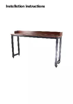
/
INSTALLATION INSTRUCTIONS proswellfrWhen resinous wood species are aut INSTALLATION INSTRUCTIONS proswellfrWhen resinous wood species are aut

INSTALLATION INSTRUCTIONS proswellfrWhen resinous wood species are aut - PDF document

quinn
quinn . @quinn
Follow
351 views
Uploaded On 2021-08-20

INSTALLATION INSTRUCTIONS proswellfrWhen resinous wood species are aut - PPT Presentation

SALT STAINSSmall green stains are frequently wood These can be removed Wood exposed to sunlight is susceptible to greying Some this natural patina If however you would prefer the wood to keep its orig ID: 868049

wood pool structure liner pool wood liner structure water ground octo type position wooden tting safety slats cover level

Share:

Link:

Embed:

Download Presentation from below link

Download Pdf The PPT/PDF document "INSTALLATION INSTRUCTIONS proswellfrWhen..." is the property of its rightful owner. Permission is granted to download and print the materials on this web site for personal, non-commercial use only, and to display it on your personal computer provided you do not modify the materials and that you retain all copyright notices contained in the materials. By downloading content from our website, you accept the terms of this agreement.


Presentation Transcript

1 INSTALLATION INSTRUCTIONS proswell.frWhe
INSTALLATION INSTRUCTIONS proswell.frWhen resinous wood species are autoclaved, the alternating pressure and vacuum can cause sticky resin residues to rise to the surface. To remove them, scrape them carefully with an appropriate tool, being careful not to touch the wood. Turpentine spirits could also be effective, but could stain the SALT STAINSSmall green stains are frequently wood. These can be removed Wood exposed to sunlight is susceptible to greying. Some this natural patina. If, however, you would prefer the wood to keep its original colour with brown tones, apply a protective coating (lazure, oil) when the product is assembled. Wood expands and contracts when and temperature. As it dries, wood contracts unevenly resulting in concern, they have no impact on the mechanical properties of the product and therefore do not fall Knots mark the places where branches were attached. The quantity and size depends on the species of wood and the sorting process. For outdoor installations, small adherent knots are acceptable. The more stringent the sorting process to limit the number and size of knots, the more To ensure the highest quality in the selection of our wood, it is sorted meticulously before planing. Planks that feature defects on both sides are taken out. Defects (knots, cracks,  ashes) are removed and the planks are This is why it is not unusual to  nd joined e

2 lements in properties of the wood. For t
lements in properties of the wood. For the same reason, imperfections on the interior surface of the pool (knots, cracks,  ashes) are entirely acceptable. JOINED WOOD SURFACE MOULDMould, caused by microscopic fungi, can grow on wood, particularly on resinous species, on which the growth and is characterised by stains raging from light to dark blue. They can be removed by wiping the surface. Remember that class IV treated wood is protected against attack by fungi that could destroy the physical and mechanical properties of the wood. For further information, please refer to Procopi’s guarantees concerning the types of wood and their treatment. VARIATIONSColour variations are common to every species of wood. Treatment of penetration of the product will depend on the wood density and grain. Weathering of wood outdoors will signi cantly attenuate COLOUR WOOD, A NATURAL MATERIAL.Being a natural material, wood will have some imperfections. These are normal and have no impact on the service life of the product.A certain number are super cial and are not covered within the scope of the CAUTION If you do not intend to assemble your pool immediately, you should store it without opening it in a well-ventilated room, or failing this, in an area protected from humidity and sunlight. If, however, you were obliged to unpack your pool, redo and restrap the pallet. Once the

3 pallets are undone, the kit must be ass
pallets are undone, the kit must be assembled within 24 to 2 �� CONTENTSForewordp-4Storage & time required for assemblyp-4Siting and preparation of the ground for Octo & Octo + poolsp.5-6Assembly of the Octo pool structurep.7-9Assembly of the Octo+ pool structurep.10-14Gaskets, laying and cutting out the liner p.15-17Assembling coping on Octo poolsp.18Assembling coping on Octo+ poolsp.19Assembling and installing laddersp.20-21Installation of in-ground and partially in-ground poolsp.22-24Maintenance and usep.25-26Safetyp.27Guaranteep.28-29Exploded view of the wooden structurep.30-31 3 We shall now explain how to assemble your pool, but rst some instructions before you begin. Please read these instructions carefully, this will allow you to prepare each stage to achieve optimum efciency. Please keep these instructions for future reference. You should take the time to go through the components using the nomenclature page enclosed with the accessories kit and make sure that no items are missing. - the productions sheets for the various kits - proofs of purchaseIf you do not intend to assemble your pool immediately, you should store it without opening it, in a well ventilated room, or failing this, in an area protected from humidity and sunlight. Once the pa

4 llets are undone, the kit must be assemb
llets are undone, the kit must be assembled within 24 hours. Once work has begun, try to avoid leaving the structure exposed to signicant climatic variations that could cause the wood to “work” too quickly. This could lead to deformations that could render the item unusable. By preference, the wooden structure should be assembled in one go on a day that is not too hot. The liner should be stored at a minimum of 20°C for at least 24 hours before it is tted. This is to render the liner more supple and thus facilitate tting. The liner should only be tted if the ambient temperature is higher than 20 °C.To prepare the ground (does not include pouring a concrete slab): shovel, rake, pick axe, cord, aluminium ruler To assemble the structure: spirit level, screw gun, mallet, measuring tape, stanley knife, metal saw, at head and cross head screw drivers, sanding paper and a ne grain le. The time taken for assembly is 2 days for 2 people (does not include excavation, pouring the slab or lling of the - To prepare the ground (does not include pouring a concrete sla shovel, rake, pick axe, cord, aluminium ruler and a spirit level. To assemble the structure: spirit level, screw gun, mallet, measuring tape, stanley knife, metal saw, at and socket wrenches, at head and cross head screw drivers, sand paper and a ne grain 

5 1;le. The time taken for assembly is 3 d
1;le. The time taken for assembly is 3 days for 2 people (does not include excavation, pouring the slab or lling of the STORAGE & TIME REQUIRED FOR ASSEMBLY Congratulations on acquiring your pool. We have taken great care with the design and manufacture of your pool to provide you with a top quality product. The wood used to make the various elements (interlocking walls, coping, ladder, etc.) was carefully selected. Outdoors, these wooden elements are subject to constant weathering: contact with the ground, temperature variations, exposure to sunlight, rain and frost, insect attack, etc. The wood’s ability to withstand this aggression depends on the origin of the wood and the method used to treat it. For this reason, we choose pine from extensive, sustainably managed forests in northern Europe. Why do we insist on this? Because the more rigorous climates above the 57th parallel favour very slow tree growth, making the wood stronger and more resilient. The wood is autoclaved, this involves subjecting the wood alternately to pressure and vacuum in order to drive the treatment chemicals into the heart of the wood as opposed to other more supercial treatment techniques such as Class IV treated wood in contact with the ground is immune to insect attack and rotting caused by humidity. Autoclave treatment is guaranteed 10 years, in accordance with standards currently in eff

6 ect.The pool coping is made of treated P
ect.The pool coping is made of treated PINE.Wood is a living material, variations in temperature and humidity can cause it to expand or contract so take care to follow the storage and assembly instructions concerning the wooden structure. Similarly, prolonged exposure to UV light can cause wood to grey. These are natural phenomena that in no way effect the service life of the products. To preserve the original colour, use a colourless wood nish. You could alternatively opt for a coloured nish or treat the wood with a colourless oil to slow the decoloration process. Before applying the nish, check that it is microporous and will allow the wood to breathe. Make sure that the product will not migrate (wet wood) over time to the interior of the structure and damage the liner. Ideally, the nish should be applied before assembling the pool structure. 4 This is the most important step in the procedure as the pool site will determine the service life of your pool. There are some rules that must be respected. Given the vast number of possible variations (slope, type and homogeneity of the ground, possible issues with drainage, etc) we cannot provide recommendations for every possible permutation here. Some optional steps, such as pouring a concrete slab, laying foundations, footing, laying drains, etc will require assistance from professionals who will be able to We w

7 ill explain how to prepare the ground wi
ill explain how to prepare the ground without any concrete, the objective being to achieve a at, level bearing surface. In as far as possible, avoid siting your pool under trees (to stop you pool from being lled with leaves) or near rises or dips in the ground that could expose children to danger. Do not assemble your pool under electrical cables. The pool should be at least 3.50 m from any electrical source (French safety standard C15-100). On a slope, never back ll under your pool to bring the bearing surface level, always cut into the upward slope. Lastly, avoid preparing the ground and assembling the pool while a strong wind is blowing.How should the pool be oriented? Ideally, the pool should be oriented so that the skimmers are facing into the prevailing wind. This will determine the nal orientation of your pool and the manner in which it will lie in your garden, notably in the OCTO POOLS(ABOVE GROUND CONFIGURATION ONLY. ADVISE AND INSTRUCTIONS FOR IN-GROUND OR PARTIALLY SUNKEN CONFIGURATIONS ARE ILLUSTRATED AT THE END OF THIS DOCUMENT).That is properly consolidated soil that has not been subject to recent backll. Even after To begin, clear the ground of plants and other necessary). Make sure that you smooth out any bumps or rough areas that could damage the underlay, or more seriously, the liner. After a rough preparation of the surface, plant a stak

8 e in the centre of the circle and mark t
e in the centre of the circle and mark the point where it comes into contact with the ground. than the radius of your pool, go around the circle checking that the ground is level. This operation requires two people (one to make sure that the bottom of the wood corresponds to the mark on move the wood around the entire circumference to ensure that the surface is perfectly level). SITING AND PREPARATION OF THE GROUND FOR 5 INSTALLATION INSTRUCTIONS proswell.fr Trace out site of the pool and clear the ground of plants, grass and other miscellaneous objects. Next, level and smooth the surface using a spade, rake and a pickaxe (if necessary). Make sure that you smooth out any bumps or rough areas that could damage the underlay, or more seriously, the liner. Make sure that the bearing surface is completely  at and perfectly level. Once the ground has been prepared, use string to mark out the longitudinal axis (A1) of your pool and then the transversal axis (A2) perpendicular to the axis A1. LengthWidth (ABOVE GROUND CONFIGURATION ONLY. ADVISE AND INSTRUCTIONS FOR IN-GROUND OR PARTIALLY SUNKEN CONFIGURATIONS ARE ILLUSTRATED AT THE END OF THIS DOCUMENT). lengthwidth+460460330+540540330+640640400+840840490Pool sizes 6 ASSEMBLY OF THE OCTO POOL STRUCTURE Fit the 4 half slats (type A - smooth side facing down) together with 4 male/ female slats (type B), grooves facing down, Befo

9 re you begin, familiarise yourself with
re you begin, familiarise yourself with the nomenclature enclosed in the “Accessories” kit and the exploded view (at the end of this notice) that corresponds Determine the nal orientation of your pool, by preference, the skimmers should be oriented so that they are facing into the prevailing winds. Skimmers must be mounted on a While assembling the walls, make sure that each slat is fully engaged before starting on the next. You may need to use a hammer and a clamp to remedy any slight warping of the slats. Do not strike the wood directly, use the protective brace (provided). During assembly, check regularly that the walls are level and the 4 diagonals are equal in length.To avoid the risk of injury or damage to the liner, take care to eliminate any splinters during and after assembly.will need to incorporate the 2 slats specially prepared to around the pool with 3 type F slats and 4 type G half-slats Attach the nishing proles (type H) to the exposed edge inserted into holes pre-drilled in the axis. 4 5 6 7 3 Fit together the remaining slats (type B) taking care to position the slat that will hold the return tting (type C) and the machined slat (type D) correctly. The slat that will hold the return tting (type C) should be positioned over that will hold the return tting slat (type C) should be positioned just underneath the machined slats.

10 The type D slat is positioned on the sam
The type D slat is positioned on the same side in the last row of 7 ASSEMBLY OF THE OCTO POOL STRUCTURE mounted after the pool is lled. Pre-drill the wall from using 2 screws (5x100 mm sachet l) taking care to position them 3 mm below the top of the structure. Remove any splinters that may have been raised during this process. The are 3 wooden brackets per side (except the side centre of the slat, the other 2 equidistant on either side of be positioned 75.5 cm apart and equidistant from the Screw a mounting plate to the top of each wooden bracket (wooden bracket kit) . Make sure that each plate IMPORTANT !Check that the structure is correctly assembled before mounting the liner locking track. To do this:use a spirit level to check that the structure is horizontal around the entire periphery. - check that the 4 diagonals are equal in length.Fix any imperfections before continuing. wooden structure. Before mounting the liner locking track, pre-drill using a Avoid over tightening, this could cause the screws to break through the track. 8 9 10 11 12 8 ASSEMBLY OF THE OCTO POOL STRUCTURE ASSEMBLY OF THE OCTO POOL STRUCTURE Mount a corner junction piece (junction+corner blister pack) in each corner using 2 SS screws (bag E) inserted through the notches intended for this purpose. Make sure that these parts are ush with the top of the pool wall. Each wall will Prepare the 8

11 additional pieces of track according to
additional pieces of track according to the table below. Before making the cuts, check that the total length of the track is equal to the distance between two corner pieces less 2 mm to allow for the corner pieces. Make sure that the cuts are straight and clean. Deburr the cuts using the ne grain le. Fit the long section into the corner piece. Bend the track to facilitate tting onto the junction piece. Hold the track in position using a screw 2 cm from each end. Then complete attachment of the track by inserting screws at 20 cm FITTING THE UNDERLAY:The ground underneath the underlay should be absolutely at and free of any bumps or rough areas. Because of the pressure exerted by the water, even the smallest bump will be visible underneath the liner. After clearing the ground, spread a layer of sand mixed with cement (1 part cement to 7 parts sand) over the oor of the pool and compact it. This layer should be no more than 1 cm deep. (The sand and cement are not supplied). Unfold the underlay in the pool taking care to line it up correctly with the corners. Smooth out any wrinkles. The underlay will be slightly smaller than the pool structure. 13 14 15 16 17 18 9 INSTALLATION INSTRUCTIONS proswell.frASSEMBLY OF THE OCTO+ POOL STRUCTURE The pool structure is mounted in two stages:- Stage 1, excavation of the site and installation of the cradles designed to re

12 inforce the lateral walls. A cradle comp
inforce the lateral walls. A cradle comprises a cross beam, vertical posts and metallic plates to be bolted together. - Stage 2, assembly of the wooden structure and  tting of the additional items (liner, coping, etc.).We recommend that the pool structure be Before you begin, familiarise yourself with the nomenclature page (enclosed with the corresponds to your pool.You will need to dig shallow trenches to hold the cradles. Make sure that these are parallel to each other and to the A2 axle. The number of trenches required will depend on the pool model, refer to the illustrations corresponding to your pool. Trenches should be regular and sized to hold the cradles in the right position. Only one trench is requried for the Octo 460. Lay the cradle components out beside the trench and  t them together (using the cradle kit). Once the cradles have been assembled, place them in the trenches and block them in position using wet compacted sand if necessary. During this operation, check that the cradles are level, straight, aligned and parallel. Fill the trenches with wet, compacted sand. Important ! Make sure that the cradles are buried to the correct depth. 19 20 21 22 23 24 L slab and create a peripheral drain. 10 INSTALLATION INSTRUCTIONSproswell.frASSEMBLY OF THE OCTO+ POOL STRUCTURE (CONTD.) - Before beginning assembly, identify the various slat types with reference

13 to the exploded view at the end of this
to the exploded view at the end of this - Establish the  nal orientation of your pool, the skimmer should be oriented facing into prevailing winds. The skimmer - While assembling the walls, make sure that each slat is fully engaged before starting on the next. - You may need to use a hammer and a clamp to remedy any slight warping of the slats. Do not strike the wood directly, use the protective brace (provided). - During assembly, check regularly that the walls are level and the 4 diagonals are equal in length.- To avoid the risk or injury or damage to the liner, take care to eliminate any splinters during and after assembly.- Please refer to the various illustrations provided in this document.- If you intend to  t your pool with a counter swim treadmill, you will need to incorporate the 2 slats specially prepared Fit 2 type A half-slats and 2 type C half slats together with 4 type B wall slats according to the illustration above. The male side (double tongue) should face upwards (see the detail below).Fit the remaining slats together using type B slats on the short sides and type D slats on the long walls. Take care to correctly position the pierced slats (type E) that will hold the return and vacuum  ttings, the bottom skimmer slat (type F) and, if necessary, the 2 optional slats from the counter swim unit kit. (Refer to the exploded view at the end of this d

14 ocument for the position of these slats)
ocument for the position of these slats). In the case of a skimmer, the slat that will hold the return  tting (E) should be positioned above 4 type B slats + 1 type A slat. The type F slat should be located on the same side in the last row of this step. Note the position of the 25 26 Pool measurements 11 ASSEMBLY OF THE OCTO+ POOL STRUCTURE (around the pool, tting 2 type H slats, 1 type l slat and 4 type J half-slats into position as shown. using 4 3.1x75 mm screws (bag L) inserted through holes pre-drilled at regular intervals along the axis.Working from the outside, screw the metallic posts (pre-drilled) onto the wooden walls using 6x40 mm screws from bag C. Check their verticality. Position two decorative proles (Q) on either side of each post and fasten them together using 3 5x70 screws (bag C) as The wooden brackets are designed to support the coping after the pool is lled. Pre-drill the wall, then, working from inside the pool, fasten each coping support bracket (L) in position using 2 5x100 mm screws (bag l), taking care to ensure that each bracket is 3 mm beneath the top of the pool structure. Check the verticality of each 27 28 29 30 31 32 33 540 & 460 640 840 12 INSTALLATION INSTRUCTIONSproswell.fr ASSEMBLY OF THE OCTO+ POOL STRUCTURE ( ASSEMBLY OF THE OCTO+ POOL STRUCTURE (On the wall holding the skimmer, position 1 coping from the skimmer axis a

15 s shown. each support bracket. Make sure
s shown. each support bracket. Make sure that each plate is  ush with the top of the pool structure. Bevel the holes in the plate before  xing the plates in position. 34 36 37 38 39 35 L 460 SkimmerFiltration unit+46060 cm50 cm+540+64075 cm+840 13 ASSEMBLY OF THE OCTO+ POOL STRUCTURE ( IMPORTANT !Before you begin to install the liner locking track, check that the structure was correctly assembled. - Using a spirit level, go around the entire structure checking that it is horizontal. - Check that the four diagonals are equal in length. - Correct any defects.- The liner locking track should be tted such that it is ush with the top of the wooden structure. - Check the length of liner locking track required before trimming it. - Pre-drill the walls using a Ø 3 mm drill bit and x the liner locking track in position. - Avoid over tightening, this could cause the screws to break through the track. IMPORTANT! The ground underneath the underlay should be absolutely smooth at and free of any foreign bodies. Because of the pressure exerted by the water, even the smallest bump will be visible underneath the liner. After clearing the ground, spread a layer of sand mixed with cement (1 part cement to 7 parts sand) over the oor of the pool and tamp it down. Unfold the underlay in the pool taking care to line it up correctly with the corn

16 ers. Smooth out any 44 45 Octo +460 poo
ers. Smooth out any 44 45 Octo +460 pools - tting the liner locking rails (with junction strips) Octo +640 pools - tting the liner locking rails (with junction strips) Octo +540 pools - tting the liner locking rails (with junction strips) Octo +840 pools - tting the liner locking rails (with junction strips) (to be trimmed) (to be trimmed) (to be trimmed) (to be trimmed) 40 43 41 42 14 Before tting the liner, glue one of the 2 rectangular self-adhesive gaskets (pool tting skin pack) around the Make sure that the holes in the gasket are correctly aligned with the holes in the skimmer.IMPORTANT ! The ideal temperature for laying liner is between 18° and 25°C. Outside this range, the liner will be either two rigid or too pliant and will be difcult to t. On very hot days, lay the liner early in the morning. During cold weather (less than 18°C), store the liner somewhere warm for as long as possible to increase it’s suppleness and do not take it out Place the liner in the centre of the pool and unfold it. When it is unfolded, the liner will form either an octagon or an elongated octagon on the ground, depending on the pool model. Line the corners up with the corners of the pool structure. Working in bare feet from inside the pool, t the liner lip into the liner locking track, continue around the pool. CAUTION: The vertical seam than

17 joins the band that covers the walls sho
joins the band that covers the walls should not be on the wall that holds the skimmer. If this is the case, turn the liner.While tting the liner, insert wooden half pegs (provided) in the liner locking track to hold it in position in the corners and at regular intervals around the periphery. This will help position the liner and stop it from slipping in the track. Keep the pegs in position until the pool has been lled with water.Make sure that the bottom corners of the liner correspond to the corners of the pool structure. You will note that the liner is slightly smaller than the structure, this is normal and necessary to ensure correct tension on the liner after the pool has been lled with water. Make sure that the liner is spread out over the entire surface of the pool. Leave the liner as is until the warmth of the sun eases out the creases caused by folding (this will take a few hours).In the event that you need to move the liner, do not slide it in the track. Take it out of the track by pulling upwards on the lip and reposition it. Sliding the liner in the track can cause it to tear just below the lip (this type of damage will not be covered by any guarantee). 46 47 48 49 50 �� FITTING & CUTTING OUT THE LINER 15 55 Once the liner has been hung and is correctly positioned, ll the pool with 2 cm of water. Push any creases towards

18 or overlled (contains more than 2 c
or overlled (contains more than 2 cm of water). Stick the self-adhesive gaskets to the return tting and Locate the holes in the throughwall ange and mark Screw the ange (tted with its gasket) into place using the countersunk SS screws M5x16 from the pool tting skin pack. Tighten the screws alternately to ensure a 51 52 53 54 Once the liner is correctly hung and positioned and creases have been eliminated, continue lling the pool (underwater light or return tting depending on their Cut out the liner inside the vacuum tting and return 16 Screw the multi- directional eyeball assembly into the return tting body. The eyeball should be pointed left to facilitate the ow of (Prior to assembly, apply a layer of silicon grease to the eyeball and its housing to facilitate its movement and subsequent removal). 56 Locate the 4 corner holes of the mouth and mark them with a pen. Position the ange such that its corner holes are aligned with the points marked in pen. Use a small screw driver or punch to pierce the liner at the 4 points marked and x the ange in position with the gasket against the liner. Once the 4 corner screws are in place, continue, inserting a screw through each hole. Avoid over tightening, this could deform the ange. Tighten the screws alternately to ensure an even and leaktight t. Cut awa

19 y the liner inside the ange. Keep t
y the liner inside the ange. Keep the off-cuts for future repairs.able to swing freely.The skimmer basket is passed through the skimmer mouth, swing the weir towards the pool to make Place the lid on the skimmer.In the case of a ltration unit, refer to the installation 57 58 59 17 �� FITTING THE COPING ON OCTO POOLS Attach the coping elements to the mounting plates on as shown. Pre-drill lightly to ease driving of the screws. In the case of a skimmer, the outer coping plank anove the allows access to the skimmer basket. After use, secure the All that remains is to attach the 8 coping corner connecting brackets (mounting kit in the coping pack) as shown above, In the case of a skimmer, mount the latches (bag N) as 61 62 63 64 65 60 18 INSTALLATION INSTRUCTIONSproswell.fr Filtration unit A’ or B’ For instructions on mounting the coping, please refer to pages 18. On the 460+, 540+ & 640+ models it may be necessary 67 68 69 70 71Skimmer version 19 ASSEMBLING AND INSTALLING THE STAINLESS STEEL LADDER Assemble the various parts of the ladder referring to the installation instructions provided.When mounting the hand rails, do not forget the two If the pool is tted with in-pool corner steps, refer to the and counter swim module), remember that it should be opposite the wooden ladder.Fix the ladder in place according to the instruct

20 ions provided, the counter plate should
ions provided, the counter plate should be positioned under the coping. Tighten moderately. Slide the 2 rubber seals �� ASSEMBLING AND POSITIONING THE WOODEN LADDER 72 73 The stringers and the treads for the wooden steps are in the Wood kit. screws (bag K). For cleaner, more efcient assembly, we recommend that you pre- seal escutcheon screwed 20 For your children’s safety !Don’t forget to stick the safety label must be removed while the pool is not The wooden ladder is tted with two lever latches that lock it into position. The lever sections are tted to the ladder supports and the hooks are mounted under the coping (these parts are enclosed in bag K). Observe how these 2 parts correctly into position. coping. These should be positioned in line with the lever latches. Trace the position of the various elements. Remove the ladder, screw the blocking parts into position and attach the lever elements to the ladder supports. Put the ladder in The locking mechanism might differ from that illustrated here, but will function according to the same principal. 75 76 77 21 This type of conguration must be protected by one of the four safety systems that comply with French safety standards concerning safety of in-ground pools; safety barrier, alarm, safety cover or a shelter. The decree no. 2003-1389 dated 31/12/2003 render

21 s it mandatory for clients of pools inst
s it mandatory for clients of pools installed after the 1st of January to have the pool tted with a system to prevent drowning before it is lled with water. Said system must comply with either the French safety standards, or with those standards, technical specications or manufacturing procedures set out in the regulations of a member state of the European Community or another state party to the Agreement on the European Economic Area, providing for an equivalent level of safety.These provisions apply to open air pools that are partially or fully in-ground. Below, we suggest implementation congurations that show basic recommendations for non-humid ground. You should adapt these to your installation, notably, in humid areas (stagnant water, water source, zone subject to ooding, etc.) a sump drain pump may be required for efcient drainage.In any case, the drainage system must be adequate to prevent the stagnation of water that could cause the wood to rot. We recommend that you follow the installation instructions to the letter; failure to abide by these instructions will render Should you have any questions, and to ensure a quality installation, do not hesitate to contact a specialist.te.INSTALLATION OF PARTIALLY IN-GROUND OR IN-GROUND EXCAVATIONpool structure. This is necessary to prevent rotting of the Anti-root or groundWaterproong Concrete slab,

22 min. Wooden structureGroundConcrete sla
min. Wooden structureGroundConcrete slab 22 drainage under the walls of the pool. Trace the shape of the Similarly, if the ltration system is to be installed at a distance Illustrations shown in this document are valid for a ltration system housed in a box buried at the same level as the pool. After the trench under the pool wall is dug, ll it to a depth of approximately 10cm using small sized gravel. Make sure that the gravel is well compacted to avoid future subsidence that will impact the pool structure. Finish lling the trench with compacted sand, the lled trench should be level with the ground. We strongly recommend that you install the lter line, there is a risk of deformation due to depressurisation. line, mount a check vent on the return line and an easily A B Cover the portion of the wooden structure that will be Back ll around the pool, taking care not damage the structure. D C 23 Cover the portion of the wooden structure that will be Back ll around the pool, taking care not damage the structure. C D Trace The cradle trenches are dug as described previously trench to run the power cable. Similarly, if the ltration Pool height 120 cm = 116 cm After the trench under the pool wall is dug, ll it to a depth of approximately 10cm using small sized gravel. Make sure that th

23 e gravel is well compacted to avoid futu
e gravel is well compacted to avoid future subsidence that will impact the pool structure. Finish lling the trench with compacted sand, the lled trench should be level with the ground. We strongly recommend that you install the the water line, there is a risk of deformation due to depressurisation. At most, the lter should be installed return line and an easily accessible check valve on the A B 24 Wood is a living material that responds to changes in temperature and humidity; cracks and splits may appear; this is The wooden components of this pool are subjected to a Class IV autoclave treatment that complies with standards in effect, they present no danger to people or animals that may come into direct contact with the wood. To preserve the original colour, use a colourless wood nish. You could alternatively opt for a coloured nish or treat the wood with a colourless oil to slow the decoloration process. Before applying the nish, check that it is microporous and will allow the wood to breathe. Make sure that the product will not migrate (wet wood) over time to the interior of the structure and damage the liner. Ideally, the nish should be applied before assembling the pool structure. Use high quality products!!! This will guarantee that the nish will last longer. However, we strongly recommend Over time, the wood will inevitably get di

24 rty. Clean it once a year with a high pr
rty. Clean it once a year with a high pressure jet to remove dirt trapped in the pores of the wood. Take care to regulate the water pressure to avoid damaging the nish or raising wood bres. This pool is delivered as a kit and is not designed to be dismantled. This pool is designed to be used by persons 3 years of age and older. It is understood that young children and non-swimmers For your safety and that of your children, we recommend that you read and apply the safety recommendations on page 27.Use of a pool kit implies adherence to safety recommendations outlined in the maintenance and operating Ladders should only be used to enter and exit the pool. Any other use is prohibited and could be dangerous. The wooden access ladder should be taken away and stored systematically after the last person leaves the pool. This is to prevent the risk of drowning. We have designed a fast efcient locking system, use it!! Store the ladder in a dry place during the winter. There should be no means of access to the pool while it is not in use. The ladder wood should be treated in the same way as the other wooden elements. We recommend that you secure access to the nished pool with one of the measures set out in the French pool safety standard NF P 90-306, 307, 308 & 309 that is: Safety barrier - Alarm - Safety cover - Shelter.Inspect the accessible nuts and bolts regular

25 ly and carry out any maintenance require
ly and carry out any maintenance required (re-tighten, treat traces of rust, etc.). Take care with the liner of your pool, do not treat it roughly. Make sure that correct tension is maintained on the liner, failure to do so could result in tears and leaks. See the guarantee conditions at the end of these instructions. During the life of your pool it may be necessary to empty it totally. In this event, take every precaution necessary to avoid . Avoid leaving the pool empty for more than 48 hours, this could result in deformation of the structure. No diving - No walking on the coping - Never leave an empty pool uncovered WATER TREATMENT & MAINTENANCE OF THE FILTRATION SYSTEM To ensure the comfort of pool users, you will need to treat the pool water. Follow the recommendations concerning operation of the ltration group: commissioning, frequency of use for regeneration of the water, maintenance, During the pool season, the lter should be run every day for long enough to renew the entire pool water volume at least three times every 24 hours. To ensure optimal efciency of the ltration system, make sure that the water level remains correct and constant. The To ll your pool, use tap water, its pH is close to the ideal pH. If you use water from a well or some other private source you must have it analysed beforehand. You will need to test the pH of your

26 pool at regular intervals and adjust it
pool at regular intervals and adjust it if necessary to keep it between 7.2 and 7.6. Treatment chemicals for this purpose are widely available. To preserve the quality of the pool water, it will need to be tested and treated regularly. Frequency will depend on a As pool water cannot be directed into the sewage system, it must be directed as rain run-off. Familiarise yourself with the regulations concerning disposal of pool waste water in effect in the area in which the pool is locatedFailure to abide by maintenance instructions may entail serious risks to health and safety, notably of children.MAINTENANCE & OPERATION 25 MAINTENANCE & OPERATION Electrical equipment such as underwater lights that require an electrical supply must be tted and wired in according to the standards in effect. We recommend that you take great care in this matter and that you call on the services of Some models come with a bubble cover that is spread over the pool while it is not in use. The action of sunlight on the cover heats the water below and the cover helps maintain the water temperature at night. Upon removing the cover from the pool, turn it over to allow it to dry, then roll it up and store it out of the way. Never fold the bubble cover, this could cause it to tear. Wipe it down from time to time with a damp cloth. This cover should under no circumstances be considered a safety dev

27 ice. A safety winter cover (that complie
ice. A safety winter cover (that complies with the French safety standard NF P90-308) is available as an option to protect the pool. This high quality product is extremely hard-wearing and attractively nished. For storage and upkeep, follow the same instructions as for the bubble cover. Carry out a prolonged back wash of the lter. The pool should not be emptied during winter (or prolonged periods while the pool is not use). The liquid mass plays a several roles, providing thermal insulation, holding the liner and pool structure in position. Water can be siphoned from the pool or allowed to drain by gravity by moving the multiport valve to DRAIN. Water will run through the waste line. Do not run the pump during this operation. Next, disconnect the pipe underneath the skimmer so that it can act as an overow in the event the water level rises due to precipitation. Remove any water treatment chemicals from the skimmer (chlorine tablets, occulents, etc.).Unscrew the return tting face ring from inside the pool. Use a threaded winterizing plug or rubber plug (not provided) to block the return tting from inside the pool. Add an algicide and a winterizing product (not supplied) to the water.Remove the stainless steel ladder.NOTE: Winterizing is not mandatory, especially if the weather is clement and temperatures remain positive. In this case, maintain a c

28 orrect water level in the pool and run &
orrect water level in the pool and run ltration 2 to 3 hours per day. Check the water level in the pool regularly. WINTERIZING THE HYDRAULIC INSTALLATIONDisconnect the return line.Allow water to drain from the suction and return lines. Open the plug at the bottom of the lter and allow water to drain away.Do not replace the plug before putting the Open the drain plugs on the pump and pre-lter.Cut the power supply to the ltration control panel. In as far as possible, store the ltration group in a location protected from humidity. In the case of an unprotected outdoor installation, remove the pump and store it. We think that we have provided you with main information you required to use and maintain your pool, however you will nd more information in specialised guides and reviews. Don’t hesitate to consult these. As regards hygiene, there are no ofcial regulations for family pools. However, for your health and that of your family and friends, there are some rules that you should respect! Next, to maintain water purity, respect the instructions set out in the section “maintenance and operation”. Pay particular attention to treatment cycles, water testing, ltration and cleaning. The balance of your pool water depends mainly on you. Do not hesitate to inform yourself and follow the advice of the professionals. 26 ��

29 000; SAFETY DO NOT PLAY
000; SAFETY DO NOT PLAY WITH SAFETY ! ! ! - safety barrier, with a gate that is always kept closed (for example, a hedge could not be considered a Outside the pool season, the pool should be covered with a winter cover correctly positioned and Make sure that there is a telephone (land line or mobile) within easy reach of the pool to avoid leaving Take steps to prevent access to the pool if the ltration system is damaged and during maintenance MEMORISE EMERGENCY SERVICE NUMBERS AND DISPLAY THEM CLOSE TO THE POOL Fire: Ambulance: Poison centre: 27 10 year guarantee from the manufacturer against insect infestation and rotting (wood is high This guarantee does not cover natural warping of the wood (appearance of cracks, splits that in no way impact the mechanical strength of the wood) or changes in colour attributable to weathering. Defects resulting from errors in mounting or storage are also excluded from the scope of this guarantee: deformed wall slats (exposure to sunlight, assembly deferred after opening the It should also be noted that the any cutting of wood elements, for any reason whatsoever, will cancel the guarantee against insect infestation and rotting for the altered element. successful outcome of any claim made under the aforementioned guarantee will be contin

30 gent on strict adherence to its conditio
gent on strict adherence to its conditions. This guarantee does not cover corrosion that may occur over time, nor does it cover damage caused by to normal usage of the pool or its accessories. All of these guarantees apply to parts recognised as defective by our All of the components of the accessories kit are guaranteed 2 years (except the bubble cover and winter cover).- folds that appear after the liner has been tted, these can be caused by sliding of the membrane on loose soil or an uneven surface, or physico-chemical properties of the pool water that are outside the acceptable ranges: water temperature should be less than 28°C, pH should be between 7.2 and 7.6 and the concentration of the sterilising agent should be within the range - Folds that remain despite following all the instructions regarding tting of the liner should be reported immediately to your Procopi agent. Very hard water can also be the cause of this type discolouration due to the build up of calcium deposits on the membrane. Hard water (TH greater than 250 ppm) should be treated with a product to eliminate calcium and suitable for use - Stains caused by the growth of algae and micro-organisms: the pool water should be treated regularly with an appro- Stains, discolouration and wrinkles caused by direct contact with oxidizing agents (thrown directly into the pool) or pockets of excessively high conce

31 ntrations of oxidising agents (frequentl
ntrations of oxidising agents (frequently associated with failure to run ltration while the oxidising agents are dissolving).er ARTICLETerm of the guarantee as of the date of 28 ARTICLETerm of the guarantee as of FILTER + Regular back washes to clean the lter to avoid The following problems, associated with inappropriate use of the ltration components, are not covered n - “stress-cracking“ of ABS parts (valve, nuts) caused by surface reactants found in some types of grease: grease should not - The continuous expulsion of sand if sand with a grain size of less than 0.6 mm is used. (the sand supplied has the correct ARTICLETerm of the guarantee as of ARTICLETerm of the guarantee as of SUMMER The following problems, associated with inappropriate use of the pump, are not covered under the terms of - Running the pump ‘Dry’ (absence of water, clogging of the pre-lter)- Running the pump without the pre-lter ARTICLETerm of the guarantee as of ARTICLETerm of the guarantee as of RECOMMENDATION! While the cover is not rolled out over the surface of the water, it should be dried, rolled up and stored out of the sunlight.RECOMMENDATION ! Avoid placing too much traction on the bungee cord, this could pull out the eyelets.Monitor water quality during the winter. Excessively high concentrations of treatment chemicals, a pH that is too low or too hi

32 gh, could result in discoloration or dam
gh, could result in discoloration or damage to the cover materialTo prevent the development of mould during periods while the cover is not in use, take care to dry and fold the cover carefully before storing it. ARTICLETerm of the guarantee as of 29 (AUTONOMOUS FILTRATION UNIT) 30 �� EXPLODED VIEW OF THE OCTO STRUCTURE Rail PVC support bracket 31 INSTALLATION INSTRUCTIONS proswell.fr » INSTALLATION INSTRUCTIONS / OCTO & OCTO+ proswell.fr Installation instructions Weva Octo, Octo+ 07/2015 GB - Revision: D - Code : 97149997 QUALITY CERTIFICATE PEFC CONTROL CHAIN Company Control chain no. The chain of custody of the company designated hereinovercomplies with the PEFC* stipulations in effect.This certi cate was issued in accordance with the PEFC reference governing chain of custody of wood, FCBA MQ CERT 11-360. Scope Method used Average percentage method Manufacture and distribution of This certi cate attests chain of custody certi cation based on continuous monitoring. It cannot prejudge changes or decisions that could be made during the year.The list of certi ed companies is available on line www.fcba.fr and http:/register.pefc.cz * appendices 15 and 16 of the french forestry certi cation scheme, the international technical document issued by the PEFC council. Certi cate No.Valid up until 01/02/2017 Installation instr