/
MaterialandComponentSpecix00660069cax00740069ons MaterialandComponentSpecix00660069cax00740069ons

MaterialandComponentSpecix00660069cax00740069ons - PDF document

rose
rose . @rose
Follow
342 views
Uploaded On 2022-09-05

MaterialandComponentSpecix00660069cax00740069ons - PPT Presentation

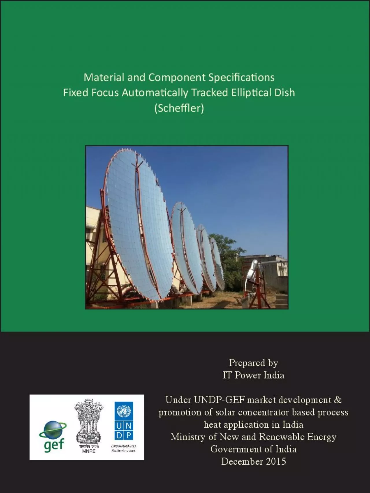
Fixed Focus Automax00740069cally Tracked Ellipx00740069cal Dish Schex00660066006Cer Prepared by IT Power India Under UNDPGEF market development promotion of solar concentrator based p ID: 950039

x00660069 x00740069 dish ons x00740069 x00660069 ons dish system x0066006c applica speci sche x00660066006c structure solar receiver heat material

Share:

Link:

Embed:

Download Presentation from below link

Download Pdf The PPT/PDF document "MaterialandComponentSpecix00660069cax007..." is the property of its rightful owner. Permission is granted to download and print the materials on this web site for personal, non-commercial use only, and to display it on your personal computer provided you do not modify the materials and that you retain all copyright notices contained in the materials. By downloading content from our website, you accept the terms of this agreement.


Presentation Transcript

Material and Component Speci�ca�ons Fixed Focus Automa�cally Tracked Ellip�cal Dish (Sche�er) Prepared by IT Power India Under UNDP-GEF market development & promotion of solar concentrator based process heat application in India Ministry of New and Renewable Energy Government of India December 2015 This booklet outlines the material and component speci�ca�ons of Fixed Focus Automa�cally Tracked Ellip�cal Dish (Sche�er) for process heat applica�on. The purpose of this booklet is to lay out the material and component speci�ca�ons of key components of the Sche�er system to serve as a reference document to maintain quality in the �eld by manufacturers supplying and installing the sys - tem. The booklet is intended to ser

ve as a guide for stakeholders interested in Con - centrated Solar Thermal (CST) system based on this technology for applica�ons in process heat for industry and help them set up a durable system which meets the necessary safety and quality standards. It is one of a series of such booklets produced to cover the �eld of commercially available CST systems marketed for process heat applica�ons in India. The speci�ca�ons for key components and sub-components of the Sche�er Dish system and their relevant parameters are outlined in an easy to understand tabular format. Wherever applicable, images of the components and schema�c diagrams have also been presented for an easy iden��ca�on of the components. The booklet has been compiled with technical inputs from the developers and manufac

turers of this technology. Inputs and sugges�ons of experts in the do - main of concentrated solar thermal systems and users have also been taken in the compila�on of this booklet. *** Preface India has a very good poten�al for solar energy, with average solar irradia�on around 4-7 kWh/m 2 /day. This abundant solar radia�on can be used to meet the demand of low to medium process heat required by various industries and in - s�tu�ons. Concentra�on of solar radia�on to produce the temperature in the range of 100 to 450˚C or more is called concentrated solar thermal (CST) tech - nology. This technology o�ers sizable poten�al across diverse range of industries and commercial establishments in India. There are six CST technologies commercial available in India, namely, Fixed foc

us automa�cally tracked ellip�cal dish (Sche�er) Dual axis tracked paraboloid dish Fresnel re�ector based dish (ARUN dish) Single axis tracked parabolic trough concentrator Non-imaging concentrators Linear Fresnel re�ector About the Sche�er dish Technology Sche�er dish is a small lateral sec�on of a paraboloid, which concentrates sun’s radia�on over a �xed focus, with an automa�c single axis tracking. Sche�er dish is made of number of �at shaped mirrors or re�ec�ve �lms which are mounted on a structural frame. The dish rotates about north-south axis parallel to earth’s axis to track the sun’s movement. The axis of rota�on passes through the centre of gravity of the re�ector and

that’s how the re�ector al ways maintains its gravita�onal equilibrium. The sche�er re�ector also performs change in inclina�on angle while staying directed to sun, in order to obtain sharp focal point. Focus is �xed at distance of focal length of the paraboloid along the axis of the paraboloid. Receiver at a �xed loca�on captures the concentrated heat and transfers it to water/thermic �uid to generate hot water/hot thermic �uid or high pressure steam. Background Key components of Sche�er Key components of Sche�er dish based system can be classi�ed on the basis of SCHEFFLER Re�ector Re�ector dish Receiver Dish stand Tracking System BALANCE OF SYSTEM Piping and Insula�on Instrumenta�on and

Safety Mechanism Heat Storage System Key design variants Sche�er dish is currently available in two design variants, namely 2 Sche�er Dish 32 m 2 Sche�er Dish Sche�er 16 m 2 2 The important characteris�cs of these designs are as follows Parameter 2 32 m 2 Average Aperture Area 2 2 Shadow Free Area 2 2 Steam, hot water, Steam, hot water, Delivery capacity Up to 12 bar pressure, Up to 180 C temperature Up to 12 bar pressure, Up to 200 temperature Weight Minimum 400 Kg Minimum 800 Kg End-use applica�on Sche�er dish is used for the low-medium process heat applica�ons. dish can a�ain the temperature up to 150-200°C as per the speci�c requirements in industries, commercial & residen�al complexes, religious places, etc. A typical 16 m 2 Sche�

006C;er Dish has thermal capacity equivalent to 30,000 Kcal/ day to 35,000 Kcal/day depending on the manufacturing precision and DNI on a clear sunny day. Schema�c diagram of CST based System with Sche�er Dishes (Courtesy: CSH India) 3 Some of the typical applica�on areas of Sche�er dish are: Food processing Community cooking Solar-assisted comfort cooling Laundry Pharmaceu�cal Drying and dying The design con�gura�on of an industrial process heat solar system depends on the speci�c applica�on. It may consist of one or more number of Sche�er dishes in a system. Sche�er dishes have been installed in various thermal applica�ons across the industries including laundry in hotels, cooking in religious and educa - �onal ins�tu

40069;ons, comfort cooling in o�ces, boiler feed water hea�ng in chemi - cal process industries amongst others. There are 9 manufacturers of this technol - ogy and more than 70 case speci�c examples of Sche�er dish systems installed across India. List of few installa�ons is given in Annexure. Development of the Sche�er dish requires component and material standards to be followed for maintaining the quality in the �eld by the manufacturers and assurance of the quality to the end-user. The following sec�on covers detailed speci�ca�ons of various components and materials of sche�er dish. *** 4 Collector The collector of Sche�er Dish is an assembly of �at shaped solar grade glass mirrors or Aluminium mirror re�ectors arrange

d on a structural steel framework. The mirrors are arranged to give a paraboloidal shape and re�ect the incident solar radia�on to a common point, i.e. the receiver. Speci�ca�ons Mirror Parameter Speci�ca�on Type Solar grade mirror with low iron content or Aluminium re�ector with glass like �nish for an outdoor use. Aluminium re�ectors should have a proper back support for the precise re�ec�ve surface area. Material and Component Speci�ca�ons SCHEFFLER DISH Parameter Speci�ca�on Material Tempered and toughened Solar grade glass/Glass infused Aluminium/Aluminium tested for scratches and durability. Flat mirror cut in required sizes for di�erent models Size All dimensions of a m

irror should be less than the diameter of the receiver 2-3 mm for Solar Grade Mirror/ 0.5mm for Aluminium Re�ector Re�ec�ve Coa�ng High quality silver back coa�ng Re�ec�vity At least 90% Protec�ve Coa�ng/ Edge sealing mirrors for di�erent Sizes) Standard weather protec�on coat on all the sides a�er grinding the corners with the help of emery paper and applica�on of appropriate coa�ng on solar grade mirrors Special weather protec�on coat to be applied for back side of mirrors to be used in the coastal and industrial region with high pollu�on levels. Durability At least 10 years for Solar Grade Mirrors and 10 years for Aluminium mirrors Speci�ca�ons Mirror Support Structure Parameter Speci�

660069;ca�on Cross bar structure consis�ng of square bars and angle sec�ons to form a shape of parabola with metal channels bolted above the square bars for �xing mirror Material All sec�ons & bars made of Standard mild steel and Parabolic Shape structural components Various hallow sec�ons have variable thickness. Protec�on from corrosion Applica�on of two layers of red oxide paint over the cleaned bars and sec�ons followed up by applica�on of two layers of enamel paint Applica�on of red oxide followed by applica�on of a layer of primer plus two layers of epoxy paint and one layer of PU (Polyurethane) coat on bars and sec�ons cleaned with copper slag Strength & Durabil - Designed to withstand 160 Km/hr. of wind speed with a life span of 20 yea

rs 7 Fixing of mirrors on Support Structure On the base structure with the help of industrial adhesive and fasteners a�er ensuring equinox posi�on of the support structure Receiver The receiver of sche�er dish is placed at the focus of the dish so as to capture the incident solar radia�on and transfer it to the thermal medium used in the system. The cri�cal component is generally a dome type absorber �xed on to the structural steel frame. The receiver works on thermo siphon principle in which cold water sinks down from header and hot water/steam moves up to the head - er. The receivers are designed according to applica�on of end user and also the size of receiver depends on the size of the focus and storage requirement. Dome Type Receiver 8 Speci�ca�ons Receiver Parameter Speci񦀆

9;ca�on Spherical Dome type receiver Material Boiler grade Mild Steel / SA516 ASTM Size & Thickness Diameter is based on the thermic �uid �ow rate required as per the process Thickness is based on the pressure required in the system 350-400 mm diameter; 8 mm thick plate for dome type receiver Strength Subjected to hydro test as per the applicable pressure ra�ng of the system Durability With normal use as per prescribed opera�on and maintenance manual, the receiver is designed to last for 15 years Statuary Requirements and Standards IBR (Indian Boiler Regula�on) and ASTM Standards as applicable to be followed Receiver Insula�on Insula�ng material with wire mesh and cladding covering the back and the side of the receiver Insula�ng Material – Light Resin Bonded (LRB) Ma�

ress OR Rockwool OR Ceramic Wool Cladding Material – Aluminium/Stainless steel Insula�on Thickness – 60 mm Cladding Thickness – 22 SWG Durable up to system life of 10 years American Society for Tes�ng and Materials Speci�ca�ons Receiver Support Structure Parameter Speci�ca�on Steel structure of standard IS sec�ons and angles �xed on a cement concrete structure Material Mild Steel structure and Cement Concrete Strength & Durability Designed to withstand 160 Km/hr. of wind speed with a life span of 20 years Fixing of receiver on Support Structure Fixed on the Mild Steel angle structure with help of nut bolts and posi�oned at focal point with receiver plane making an angle equal to la�tude angle of the loca�on with ver�cal. Dish

stand The basic framework of the dish stand is a steel structure. The structure is designed to withstand wind speed in opera�ng condi�ons as well as in parked stage as per the applicable structural design code. The overall system rests on a civil founda�on. The rotary support, counter weight and other equipments like an electric motor for tracking are a�ached on the Dish stand. Receiver Insula�on Receiver Support Structure Speci�ca�ons Dish Stand Parameter Speci�ca�on Rectangular/Triangular conical shape steel structure consis�ng of standard IS (Indian Standards) sec�ons, pipes and angles �xed on a cement concrete column Material Mild Steel structure and cement concrete Protec�on from corrosion Applica�

740069;on of two layers of red oxide paint over cleaned bars and sec�ons followed up by applica�on of two layers of enamel paint Applica�on of red oxide paint followed up by applica�on of a layer of primer plus two layers of epoxy paint and one layer of PU coat on bars and sec�ons cleaned with copper slag Strength & Durability Designed to withstand 160 Km/hr. of wind speed with a life span of 20 years Tracking System Tracking system enables the dish to be focused towards the sun to capture maximum possible direct radia�on during the day. It also tracks the sun as it changes its posi�on during the seasons. Tracking system may include the following set of equipments – Electrical motor, Gearbox, Sprockets and chains, Counter weight with rope, Screw sha�, solar ra - dia�on sensor, Wind sen

sor and Timer Speci�ca�ons Tracking System Parameter Speci�ca�on Automa�c mechanism (Microprocessor based/Timer based) for daily tracking and manual mechanism for seasonal tracking in 16m 2 sche�er dish system Automa�c mechanism (Timer based) for daily track - ing and Semi-Automa�c mechanism with the help of switches for seasonal tracking in 32 m 2 sche�er dish system Features Automa�c reversal in the evening to bring it back to the Accuracy: +/- 0.2 ˚ Weather Protec - Standard weather protec�on box for all outdoor tracking components. Rotary support Rope Counter Weight Motor Chains and sprockets Parameter Speci�ca�on Strength & Durability All the standard pieces of equipments rela

ted to the tracking system are designed to withstand 160 km/hr. of wind speed with a life span of 20 years Equipment used Standard Electric Motor, Rope with counter weight, Gear box, Chain, Timer and Threaded Bars for �mer based daily tracking Set of photo sensors, chains, motors, gears and actuators for microprocessor based daily tracking Screw sha�s on top and bo�om for the seasonal tracking Balance of plant normally includes a number of components such as heat trans - fer pipes & support structure, instrumenta�on & safety mechanism and storage tank (op�onal) to control the �uid �ow and temperature. The heat transfer pipes carry �uid and transfer the heat received by it to an end use applica�on. Fluid circulates in the system at a certain desired rate. Speci�ca񴀆

9;ons Parameter Speci�ca�on As per IBR schedule 40 for high temperature and pressure BALANCE OF SYSTEM Heat Transfer Pipe Parameter Speci�ca�on Material Tantalum pipes or Glass lined pipes for acidic �uid condi�on Size Diameter of pipe depends on the �ow rate of �uid Thickness is based on the pressure required in the system Working Fluid Water/Thermic Fluid Temperature & Pressure Range Up to 180˚C temperature & Up to 12 bar pressure for 2 Up to 200˚C temperature & up to 12 bar pressure for 32 m 2 Strength & Durability IBR standards as applicable to be followed Insula�on LRB ma�ress with an aluminum cladding over the pipe Insula�on Thickness – depending on temperature changes Cladding Thickness – 22 gauge Durable up to system life of 10 years Para

meter Speci�ca�on Instruments IBR standard Strainer, Pressure Reducing Valve, Pressure Gauge, Temperature sensors Aluminium sheet cover to protect the equipment against di�erent weather condi�ons Steel structure of standard IS sec�ons and angles �xed on a cement concrete structure Material Mild Steel structure and cement concrete Protec�on from corrosion Applica�on of two layers of red oxide paint over cleaned bars and sec�ons followed up by applica�on of two layers of enamel paint Applica�on of red oxide paint followed up by applica�on of a layer of primer plus two layers of epoxy paint and one layer of PU coat on bars and sec�ons cleaned with copper slag Strength & Durability Designed to withstand 160 Km/hr. of wind speed with a life span o

f 20 years Typical Pressure Valve Typical Flow Meter Support Structure Storage system The thermal storage subsystem is a part of the circula�on system. It extracts heat from the circula�ng �uid when the temperature becomes too high. Likewise when the temperature is too low, it supplies stored heat to the �uid. Speci�ca�ons Storage Tank Parameter Speci�ca�on Material Boiler grade Mild Steel Size & Thickness Diameter is based on the thermic �uid �ow rate required as per the process under considera�on Thickness is based on the pressure required in the system Storage Material Hot Water/Steam Strength & Dura - Subjected to hydro test as per the applicable pressure ra�ng of the system With normal use as per prescribed opera�on and mainte

nance manual, it is designed to last for 20 years Insula�on LRB ma�ress with Aluminum cladding over the pipe Insula�on Thickness – depending on temperature changes Cladding Thickness – 22 SWG Should withstand up to system life of 10 years Storage Tank Storage Support Structure Support Structure Parameter Speci�ca�on Steel structure of standard IS sec�ons and angles �xed on a cement concrete structure Material Mild Steel structure Protec�on from corrosion Applica�on of two layers of red oxide paint over cleaned bars and sec�ons followed up by applica�on of two layers of enamel paint Applica�on of red oxide paint followed up by applica�on of a layer of primer plus two layers of ep - oxy paint and one layer of PU coat on bars and

sec - �ons cleaned with copper slag Strength & Durabil - Designed to withstand 160 Km/hr. of wind speed with a life span of 20 years *** Annexure List of a few prominent Installa�ons State System Size Applica�on ITC Maurya, New Delhi Laundry B S Paper & Board Mill, Process Heat JSSM Boys and Girls Hostel, Mysore Karnataka Steam Cooking Shan�van, BrahmaKu - maris, Mount Abu Rajasthan Steam Cooking Mahindra Vehicle manufacturers, Pune Maharash - tra Space cooling applica - VAM Purple Crea�ons, Pune Maharash - tra Process Heat applica - �on for steam ironing Narainpur Chha�s - garh Steam Cooking Educa�on Trust, Juna - garh Gujarat Steam Cooking Govind Bhawan Mess, IIT Roorkee, Roorkee U�ara - Steam Cooking Javahar Navodaya Vidyalaya, Leh, Ladakh Steam Cooking Manufacturers There are six

Sche�er Dish manufacturers in India at present. Details of the manufacturers can be found on MNRE website. Prepared by IT Power India Contact: For more details on the manufacturers/suppliers, government sup - port, applica�ons, technologies and successful installa�ons please visit: www.mnre.gov.in OR www.cshindia.in OR contact Project Management Unit UNDP-GEF CSHP, Ministry of New and Renew - able Energy, Block 3, CGO Complex, Lodi Road, New Delhi-110003. Telefax: 011-32314365/24363638, Email: singhalak@nic.in Toll Free Helpline No. 1800 2 33 44 77 could be accessed Mon - day through Friday between 9:30am to 6:30pm and on Saturday 9:30am to 1:30pm Prepared for the Ministry of New and Renewable Energy, Govern - ment of India, under the UNDP-GEF project on Concentrated Solar Heat by IT Power Consul�ng Pvt. Ltd, New Delhi-110019 website: www.itpo

Related Contents


Next Show more