/
International Journal of Computational Engineering Research (IJCER)
.. International Journal of Computational Engineering Research (IJCER)
..

International Journal of Computational Engineering Research (IJCER) .. - PDF document

sherrill-nordquist
sherrill-nordquist . @sherrill-nordquist
Follow
400 views
Uploaded On 2015-12-04

International Journal of Computational Engineering Research (IJCER) .. - PPT Presentation

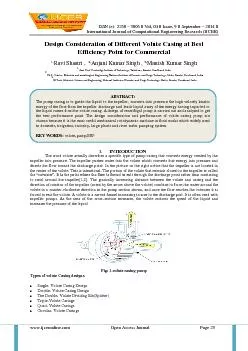
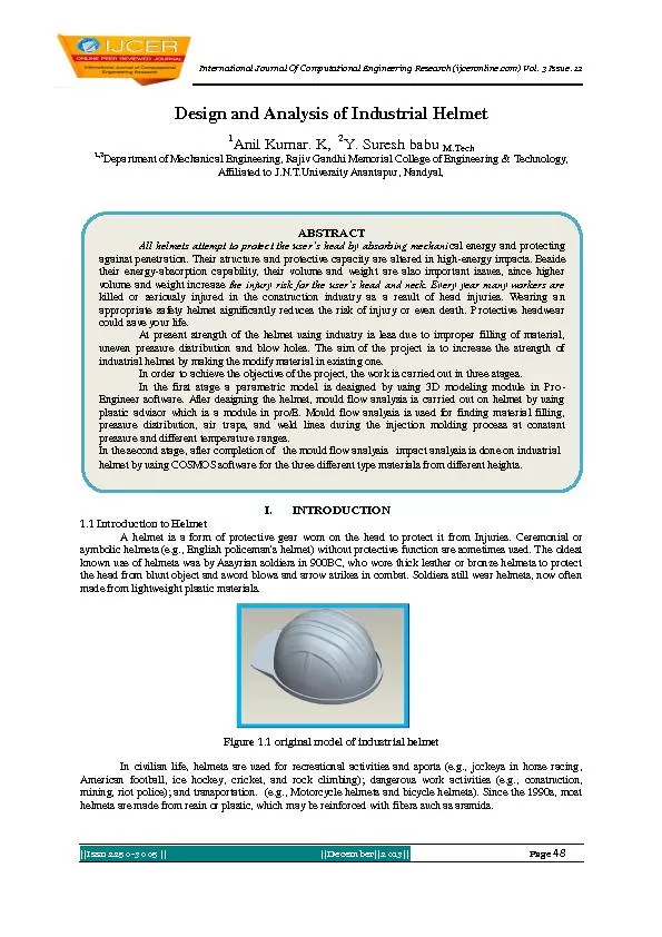
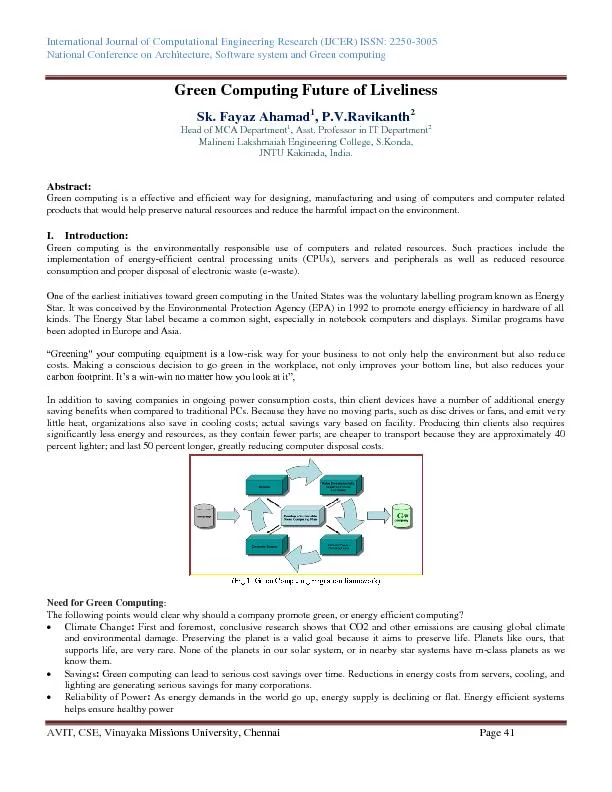
ISSN e 2250 x2013 3005 Vol 04 Issue 9 September x2013 2014 wwwijceronlinecom Open Access Journal Page 23 Design Consideration of Different Vo ID: 213572

ISSN (e): 2250 – 3005 || Vol

Share:

Link:

Embed:

Download Presentation from below link

Download Pdf The PPT/PDF document "International Journal of Computational E..." is the property of its rightful owner. Permission is granted to download and print the materials on this web site for personal, non-commercial use only, and to display it on your personal computer provided you do not modify the materials and that you retain all copyright notices contained in the materials. By downloading content from our website, you accept the terms of this agreement.


Presentation Transcript

ISSN (e): 2250 – 3005 || Vol, 04 || Issue, 9 || September – 2014 || International Journal of Computational Engineering Research (IJCER) www.ijceronline.com Open Access Journal Page 23 Design Consideration of Different Volute Casing at Best Efficiency Point for Commercial 1, Ravi Shastri , 2, Anjani Kumar Singh , 3, Manish Kumar Singh 1, Asst. Prof. Cambridge Institute of Technology, Tatisilway, Ranchi, Jharkhand, India 2, Ph.D. Scholar, Materials and metallurgical Engineering National Institute of Foundry and Forge Technology, Hatia, Ranchi, Jha rkhand, India 3, M.Tech, Materials Science and Engineering, National Institute of Foundry and Forge Technology, Hat ia, Ranchi, Jharkhand, India I. INTRODUCTION The word volute actually describes a specific type of pump casing that converts energy created by the impeller into pressure. The impeller pushes water into the volute which converts that energy into pressure and directs the flow toward the discharge point . In the picture on the right notice that the impeller is not located in the center of the volute. This is intentional. The portion of the volute that extends closest to the impeller is called the “cutwater”. It is the point where the flow is forced to exi t through the discharge point rather than continuing to swirl around the impeller [1,2] . The gradually increasing distance between the volute and casing and the direction of rotation of the impeller (noted by the arrow above the volute) combine to force the water around the volute in a counter - clockwise direction in the pump section shown, and once the flow reaches the cutwater it is forced to exit the volute . A volute is a curved funnel increasing in area to the discharge port. It is often used with impelle r pumps. As the area of the cross - section increases, the volute reduces the speed of the liquid and increases the pressure of the liquid. Fig: 1 .volute casing pump Types of volute Casing designs  Single - Volute Casing Design  Double - Volute Casing Design  The Double - Volute Dividing Rib(Splitter)  Triple - Volute Casings  Quad - Volute Casings  Circular - Volute Casings ABSTRACT: The pump casing is to guide the liquid to the impeller, converts into pressure the high velocity kinetic energy of the flow from the impeller discharge and leads liquid away of the energy having imparted to the liquid comes from the volute casing. A design of centrifugal pump is carried out and analyzed to get the best performance point. The design consideration and performance of volute casing pump are chosen because it is the most useful mechanical rotodynamic machine in fluid works which widely used in d omestic, irrigation, industry, large plants and river water pumping system. KEY WORDS : volute , pump,BEP Design Consideration Of Different Volute Casing … www.ijceronline.com Open Access Journal Page 24 Single - Volute Casing Design: Single - volute pumps have been in existence from Day One. Pumps designed using single - volume casings of co nstant velocity design are more efficient than those using more complicated volute designs. They are also less difficult to cast and more economical to produce because of the open areas around impeller periphery. Theoretically they can be used on large as well as small pumps of all specific speeds [3] . The single volute pump impeller will deflect either 60° or 240° from the cut water depending upon which side of the pump's best efficiency point (BEP) you are operating. Fig. 2 Single - Volute Casing of pump In all volute pumps the pressure distribution around the periphery of the impeller is uniform only at the best efficiency point ( BEP). This pressure equilibrium is destroyed when the pump is operating on either side of the BEP, resulting in a radial load o n the impeller. This load defects the pump shaft and can result in excessive wear at the wearing rings, seals, packing, or bearings. In extreme cases, shaft breakage due to fatigue failure can result. The magnitude of this radial load is given by [4,5] : Radial load = KHD 2 b 2 sp gr/2.31 where Radial force (lbs), H = Impeller head (ft), D 2 = Impeller diameter (in.), b 2 = Total impeller width including shrouds at D 2 (in.), K = Experimental constant, sp.gr = Specific gravity. Values of the experimental constant K are given in bellow figure. For a specific single - volute pump it reaches its maximum at shutoff and will vary between 0.09 and 0.38 depending upon specific speed. The effect of force will be most pronounced on a single - stage pump with a wide b 2 or a large - sized pump. It is safe to say that with existing design techniques, single - volute designs are used mainly on low capacity, low specific speed pump or pump for special applications such as variables slurries or solids h andling. Double - Volute Casing Design: A double - volute casing design is actually two single - volute designs combined in an opposed arrangement. The total throat area of the two volutes is identical to that which would be used on a comparable single - volute design. Double - volute casings were introduced to eliminate the radial thrust problems that are inherent in single - volute designs. Test measurements, however, indicate that while the radial forces in a double volute are greatly reduced, they are not comple tely eliminated. This is because although the volute proper is symmetrical about its centerline, the two passages carrying the liquid to the discharge flange often are not. For this reason, the pressure forces around the impeller periphery do not precisely cancel, and a radial force does exist even in double - volute pumps. Design Consideration Of Different Volute Casing … www.ijceronline.com Open Access Journal Page 25 Fig. 3 Double - Volute Casing of pump Values of the constant K have been established experimentally by actually measuring the pressure distributions in a variety of double - volute pumps. The data presented in above figure apply to conventional single stage double - volute pump and indicate substa ntial reductions in the magnitude of K. Tests on multistage pumps with completely symmetrical double - volute casings indicate that the radial thrust is nearly zero over the full operating range of the pump. The hydraulic performance of double - volute pumps i s nearly as good as that of single - volute pumps. Tests indicate that double - volute pumps will be approximately one to one and one - half points less efficient at BEP, but will be approximately two points more efficient on either side of BEP than a comparable single - volute pump. Thus the double - volute casing produces a higher efficiency over the full range of the head - capacity curve than a single volute. Double - volute pump casings should not be used in low - flow (below 400 Gallons per Minute) single - stage pumps . The small liquid passages behind the long dividing rib make this type of casing very difficult to manufacture and almost impossible to clean. In large pumps double - volute casings should be generally used and single - volute designs should not be considered . Triple - Volute Casings: Some pumps use three volutes symmetrically spaced around the impeller periphery. Total area of the three volutes is equal to that of a comparable single volute. The triple volute casing is difficult to cast, almost impossible to c lean, and expensive to produce. We do not see any justification for using this design in commercial pumps. Fig. 4 Triple - Volute Casing of pump Quad - Volute Casings: Approximately 15 years ago a 4 - vane (quad) volute was introduced. Later this design was applied to large primary nuclear coolant pumps (100,000 GPM, to 10 - 15,000 HP). The discharge liquid passage of these pumps is similar to that of a multi - stage crossover leading to a side discharge. There is no Design Consideration Of Different Volute Casing … www.ijceronline.com Open Access Journal Page 26 hydraulic advantage to this design.The onl y advantage of this design is its reduced material cost. The overall dimensions of quad - volute casing are considerably smaller than those of a comparable double - volute pump. Circular - Volute Casings: Several pump manufacturers have conducted tests to eva luate the hydraulic performance of pumps with circular volutes. A study of the results of these tests reveals that circular volutes improve the hydraulic performance of small high head or low specific speed units and impair the performance of high specific speed pumps. Specifically, pump efficiency is improved below specific speeds of 600. For specific speeds above 600 the efficiency of circular - volute designs will be 95% of that possible with conventional volute designs. This can be explained by rememberin g that in a conventional volute a uniform pressure and velocity distribution exists around the impeller periphery only at the BEP. At off - peak capacities, velocities and pressures are not uniform. For circular volutes the opposite is true. Uniform velocity and pressure exist only at zero flow [6] . This uniformity is progressively destroyed as the capacity is increased. Therefore, at BEP the casing losses are generally greater than those of the conventional volute. For low specific speed pumps, however, there is some gain in efficiency due to a circular volute since the benefits of the improved surface finish in the machined volute outweigh the problems created by the non - uniform pressure distribution. General Design Considerations: It was pointed out previou sly that the casing itself represents only losses and does not add anything to the total energy developed by the pump. In designing pump casings it is therefore important to utilize all available means of minimizing casing losses. However, commercial consi derations dictate some deviations from this approach , and experience has shown that these do not have a significant effect on casing losses. The following designs rules have shown themselves to be applicable to all casing designs [1 , 7, 8 ] :  Constant angle s on the volute sidewalls should be used rather than different angles at each volute section. Experience has shown that these two approaches give as good results and the use of constant wall angles reduces pattern costs and saves manufacturing time.  The vo lute space on both sides of the impeller shrouds should be symmetrical.  All volute areas should be designed to provide a smooth change of areas.  Circular volutes should be considered for pumps below a specific speed of 600. Circular volutes should not be c onsidered for multistage pumps.  The total divergence angle of the diffusion chamber should be between 7 and 13 degrees. The final kinetic energy conversion is obtained in the discharge nozzle in a single - stage pump and in both the discharge nozzle and cros sover in a multi - stage pump.  In designing a volute, be liberal with the space surrounding the impeller. In multi - stage pumps in particular, enough space should be provided between the volute walls and the impeller shroud to allow one - half inch each way for end float and casting variations. A volute that is tight in this area will create axial thrust and manufacturing problems. II. CONCLUSION In a today competitive and sophisticated technology, centrifugal pump is more widely used than any other applications because the advantages of following factors are effect on the centrifugal pump.  Its initial cost is low.  Efficiency is high.  Discharge is uniform and continuous flow.  Installation and maintenance is easy.  It can run at high speeds without the risk of separ ation of flow. In th is paper we show the what is design consideration of different volute casing at best efficiency point (BEP) for commercial aspect. In designing pump casings it is therefore important to utilize all exact dimensions as like volute throat area, volute mean diameter, volute circumferential length and minimizing casing losses. However, commercial considerations dictate some deviations from this approach, and experience has shown that these do not have a significant effect on casing. The foll owing designs rules have shown themselves to be applicable to all casing designs. REFERENCES [1] B. V. Ukhin (2007), Effect of variation in the diameter of a centrifugal dredge impeller on its characteristics, Springer Sci ence + Business Media, Inc, Vol. 41, No. 1. [2] E.C. Bacharoudis, A.E. Filios2, M.D. Mentzos and D.P. Margaris (2008) , Parametric Study of a Centrifugal Pump Impeller by Varying the Outlet Blade Angle,Bentham Open Mechanical Engineering Journal,2,75 - 83. [3] D. Rajenthirakumar & K. A. Jagadeesh (2009), Analysis of interaction between geometry and efficiency of impeller pump using rapid prototyping, Int J AdvManufTechnol, 44:890 – 899. Design Consideration Of Different Volute Casing … www.ijceronline.com Open Access Journal Page 27 [4] LamloumiHedi, KanfoudiHatem, ZgolliRidha (2010), Numerical Flow Simulation in a Centrifugal Pump,International Renewable En ergy Congress November 5 - 7,Sousse, Tunisia. [5] Beena D Baloni, S.A. Channiwala, V.K. Mayavanshi (2012) , Pressure recovery and loss coefficient variations in the two differ ent centrifugal blower volute designs,Elsevier, Applied Energy 90(2012) 335 - 343. [6] Pump handbook by Karassik [7] Energy Audit Reports of National Productivity Council. [8] British Pump Manufacturers' Association , BEE (EMC) Inputs , PCRA Literature