/
Owners Operator and Maintenance Manual Owners Operator and Maintenance Manual

Owners Operator and Maintenance Manual - PDF document

singh
singh . @singh
Follow
342 views
Uploaded On 2021-08-17

Owners Operator and Maintenance Manual - PPT Presentation

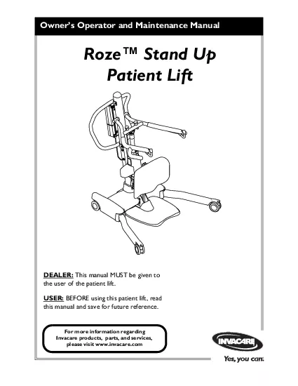
DEALER This manual MUST be given to the user of the patient liftUSER BEFORE using this patient lift read Invacare products parts and services please visit wwwinvacarecomRoze Stand Up Patient LiftRoze ID: 864937

lift patient invacare stand patient lift stand invacare battery sling warranty 1150703 1150703roze thisprocedure liftpart part roze washer actuator

Share:

Link:

Embed:

Download Presentation from below link

Download Pdf The PPT/PDF document "Owners Operator and Maintenance Manual" is the property of its rightful owner. Permission is granted to download and print the materials on this web site for personal, non-commercial use only, and to display it on your personal computer provided you do not modify the materials and that you retain all copyright notices contained in the materials. By downloading content from our website, you accept the terms of this agreement.


Presentation Transcript

1 Owner’s Operator and Maintenance Manual
Owner’s Operator and Maintenance Manual DEALER: This manual MUST be given to the user of the patient lift.USER: BEFORE using this patient lift, read Invacare products, parts, and services, please visit www.invacare.com Roze™ Stand Up Patient Lift Roze™ Stand Up Patient LiftPart No. 1150703 DO NOT OPERATE THIS EQUIPMENT WITHOUT FIRST READING AL. IF YOU ARE UNABLE TO TECHNICAL SUPPORT BEFORE ATTEMPTING TO USE THIS EQUIPMENT - OTHERWISE INJURY OR DAMAGE MAY RESULT. ACCESSORIES WARNINGInvacare products are specifically designed and manufactured for use in conjunction been tested by Invacare and are not recommended for use with "ATTENTION, see the Lift Arms. Injury t

2 o the patient and/or assistant may occur
o the patient and/or assistant may occur. WARNING - ALWAYS be aware of the Footrest, especially the patient’s position on the footrest. Injury to the patient and/or assistant may occur. 2008 "Date of Manufacture"normal household waste. They MUST be taken to a for information. TABLE OF CONTENTSPart No. 1150703Roze™ Stand Up Patient Lift SYMBOL LEGEND ..............................................................................2ODUCT ...............................................................4SPECIAL NOTES ................................................................................5LABEL LOCATION .................................................................

3 ...........6RS .........................
...........6RS ..................................................................7ft.......................................7IDELINES ...................................................8Weight Limitation...................................8Assembling the Lift.................................8Using the Sling............................8Operating the Lift....................................9Lifting the Patient...................9Transferring the PatientPerforming MaintenanceMBLY ..................................................................11ft.....................ly to the Base.........Plate to the Mast Assembly........Wall.........................Charger to the Mast

4 Assembly.....ATION ....................
Assembly.....ATION ...............................................................15Introduction...........Casters........................16Raising/Lowering the Patient Lift...........Using the Emergency StopActivating a Mechanical Emergency Release......... ........................17Charging the Battery.....THE PATIENT ................................................19Positioning the Stand Up Lift.................Lifting the Patient.......Moving the Patient......... Roze™ Stand Up Patient LiftPart No. 1150703 THE PATIENT ....................................24Introduction...........Transferring to a Commodeir.....................Transferring to a Bed....ESHOOTING ..

5 ........................................
.................................................28TENANCE ..........................................................29Inspection Checklist.....e Lift...............Detecting Wear and Damage.....................Lubricating the Lift........ctuator..................Replacing the Leg Actuators.......................ight..................LIMITED WARRANTY .....................................................................351.Safeguarding your investment.2.Ensuring long-term maintenance a3.Receiving updates with prote your registration.icable laws and regulations. Part No. 1150703Roze™ Stand Up Patient Lift wordsusedresultpropertywords. NOTICETHE INFORMATION CONTAINED IN

6 Most electronic equipment is influenced
Most electronic equipment is influenced by Radio Freqequipment in the area around such equipment. If RFI causes erratic behavior, PUSH MAINTENANCE SIGNAL WORDMEANINGDanger indicates an imminently hazardous situation which, if not avoided, will result in Warning indicates a potentially hazardous situation which, if not avoided, could result in Caution indicates a potentially hazardous situation which, if not avoided, may result in property damage or minor injury or both. Roze™ Stand Up Patient LiftPart No. 1150703 LABEL LOCATION BEFORE using the Patient Lift,READ and UNDERSTAND theOwners Manual for properoperation and safetyprocedures.WEIGHT LIMITATION 450 lbs.DO NOT

7 roll casterbase overdeep carpet, raised
roll casterbase overdeep carpet, raised carpetbindings, door frames or anyuneven surfaces that may causethe Patient Lift to tip over.DO NOT lock the casters of thePatient Lift when lifting anindividual. Casters MUST be leftunlocked to allow the PatientLift to stabilize during liftingprocedures.USE ONLY INVACARE SLINGS and LIFT ACCESSORIES.Refer to Owners Manual forprocedures.USE ONLY the appropriatePatient Lift components forThe Invacare Patient Lift is NOTa transport device. Moving aperson suspended in a sling over ANY distance is NOTRECOMMENDED. 1154560 REV. ACustomer Service: NavyLargeBlack WARNING USE ONLY INVACARE ACCESSORIES.Sling Sizes1154553 REV. A labellocat

8 edcross Part No. 1150703Roze™ Stand Up P
edcross Part No. 1150703Roze™ Stand Up Patient Lift Variesstroke.Height at Sling Hook-up - MAX.:63.5 inchesHeight at Sling Hook-up - MIN.:37 inchesBase Width OPEN:44 inchesBase Width CLOSED:26 inchesBase Height (Clearance):4.8 inchesBase Length:38.8 inchesOverall Height:49.1 inchesOverall Length:42 inchesOverall Width:26 inchesCaster Size (FRONT/REAR):4.0 inchesSling Options:Standing or TransferSling Material:PolyesterWeight Capacity:450 lbsWeight Out of Carton:117 lbsBattery:24V DC (RCHBL)Charger Input:100-240V ACCharger Output/Charging Time:29.5V DC Max 6 hoursAudio/Visual Low Battery Alarm:YesMotor Safety Devices:Anti-Entrapment*Approx. Lifts per Charge:*100-200 Cy

9 cles per chargeWarranty Pump/Electronics
cles per chargeWarranty Pump/Electronics:2 YearsEmergency Stop Button:Yes Roze™ Stand Up Patient LiftPart No. 1150703 SECTION 1—GENERAL GUIDELINES  SECTION 1 - GENERAL GUIDELINES contains important information for the safe shippingbeforeusing.useequipment.forTheInvacarepatientintendedbedoverdistanceapprovalpatient’sthethisOwner’sobserveseveralcapableInvacareStandTransferdesignedusedInvacarepatientaccessoriesmanufacturerscomponentInvacare’stheseproductswillvoidlift’swarranty.individual’sdoctor,maximumweightweightlimitationPatientovertightenmountinghardware.damagemountingthatuseMUSTweight,occur.Assistuseassistslingpatienttransportonebedwheelchair).usingtheover Part No

10 . 1150703Roze™ Stand Up Patient Lift Ass
. 1150703Roze™ Stand Up Patient Lift Assistpatient,thestandlowerpatient’stheassistsling.Thecomfortableouttransfer,possiblyinjury.Transferbottomedgebasethepatient’sTransferpatientstandinginjuryoccur.betweenpatienttransfer.launderingwithsling),sling(s)wear,frayed,brokenunsafeinjury.immediately.theslingremovedpatientremovedobject(bed,wheelchair,wheellockspreventmovingforwardsbackwards.slingscodedpatientbacklongleavesupportTheloopsslingvarioussidesequally.suresufficientsuremountingbatterymounting.occur.lift.legsthepatient’swayfootoccur.safetycomfortshouldmovingPatient Roze™ Stand Up Patient LiftPart No. 1150703 (wheelchair,bed),checklowerpatientpatientagain.transfer,withs

11 uspendedattachedtheoverframes,unevenwoul
uspendedattachedtheoverframes,unevenwouldthecausepatientliftover.UsehandlepushInvacareswivelONLYassisttheInvacaredoesthepatientDoingcausethepatientassistants.Invacareliftingpatientchair,bedtheproduct’sweightpatientweight.lockedpositionloweringpatienttransport.necessaryfirstmonthspivotwear.theworn,replaced.Performthiseverysixmonthsthereafter.overtightenmountinghardware.ThismountingCastersinspectionseverysixmonthswear. Part No. 1150703Roze™ Stand Up Patient Lift Assembling the Mast Assembly to the Basemayremovedfromstoragetransporting.properlysecuredbaseassemblybeforeuse.thisprocedure,referFIGURE2.1.1.Putlevelfloor.2.Lockcasters“A”FIGURE2.1).3.Unscrewremovebase.4.Loosen

12 knob,leavescrewedbase.5.Puttubeholebase.
knob,leavescrewedbase.5.Puttubeholebase.6.Whileassembly,7.ScrewthetheholeFIGURE2.1 Assembling the Mast Assembly to the Base Push tab down to Push tab UPto UNLOCK.DETAIL “A” - LOCKING/UNLOCKING REAR CASTERS Caster Mast AssemblyTop Knob Base Bottom Knob ASSEMBLYRoze™ Stand Up Patient LiftPart No. 1150703 thisprocedure,referFIGURE2.2removedfromtransporting.kneeproperlysecuredassemblybefore1.Pushkneemountingmastassembly.2.Putmounting3.Insertknobmountingfixblock.4.TightenAssembling the Foot Plate to the thisprocedure,referFIGURE2.31.Rotatethefootandmountingtheassembly.2.Rotateplatetowardsassembly.Thefootbottomassembly.3.Ensurelevelandsecure.FIGURE2.2 FIGURE2.3 Knee

13 Pad Knee PadMounting Bracket Quick Relea
Pad Knee PadMounting Bracket Quick Release Fix Block Foot Rest(shown in place) Top Mounting Bolt Bottom Mounting Bolt Assembly Part No. 1150703Roze™ Stand Up Patient Lift Attaching the Battery Charger Mounting Bracket to the thisprocedure,referFIGURE2.4.1.Placemountingwall2.Withpencil,3.Measuretheonemountinghole.4.Installmountinguntilbetweenscrewwall.5.Putmountingbottommountingscrew.6.Drilltwomounting7.Screwmountingscrewsbatteryintowall.securely. ble click when mounting battery on the battery charger to confirm proper mounting. Otherwise, injury or damage may occur.8.Putmounting9.Plugthewillwhenbatterycharger.FIGURE2.4 Attaching the Battery Charger Mounting Bracke

14 t to the Wall Mounting BracketMounting S
t to the Wall Mounting BracketMounting ScrewsBOTTOM Mounting Screw ASSEMBLYRoze™ Stand Up Patient LiftPart No. 1150703 Attaching the Battery Charger to the Mast Assembly outlet, make sure to unplug the battery charger from the wall outlet BEFORE using damage.thisprocedure,referFIGURE2.5.1.Removetwomylarcoveringmountingbackassembly.2.Insertscrewsmountingholes.3.Tightenscrews.4.Mountmounting5.Chargebattery. page18.FIGURE2.5 Attaching the Battery Char Battery and Battery Charger shown in place on mast assembly Part No. 1150703Roze™ Stand Up Patient Lift SECTION 3— OPERATIONIntroduction nurse, or medical assistant. Thoroughly then perform the entire lift procedure seve

15 ral times with proper supervision and a
ral times with proper supervision and a through a narrow passage, close the legs of the slong as it takes to move through the passage. When the stand up lift is through the passage, return Invacarerecommendsthatpreparationto/fromprocedures;however,canbasedcareprofessional Roze™ Stand Up Patient LiftPart No. 1150703 thisprocedure,referFIGURE3.1.•TotheCaster:•TotheCaster:up.thisprocedure,referFIGURE3.1.•TothePatientbeforelower.bothmaking•ToLowerPatientcontrol.thisprocedure,referFIGURE3.1.•Tohand•Tothisprocedure,referFIGURE3.1.•Pushemergencylowering.•ToFIGURE3.1 Operating the Patient Lift Push tab DOWN Push tab UP Caster DETAIL “A” LOCKING/UNLOCKINGTHE REAR CASTERS DE

16 TAIL “B” - HAND CONTROL DETAILSDETAIL “C
TAIL “B” - HAND CONTROL DETAILSDETAIL “C” - EMERGENCY STOPDown ButtonHand Control Emergency Button Open Legs Close Push in to stop, turn clockwise to reset. Part No. 1150703Roze™ Stand Up Patient Lift thisprocedure,referFIGURE3.2.procedurewillcontrolfunctioningproperly.activateholelabeledDownFIGURE3.2 thisprocedure,referFIGURE3.3.patientaremechanicalemergencyrelease.releaseretractpower.Useemergencyreleasebeforeemergencyreleaseprocedure.procedureshouldonlyemergencyreleaseprocedureunreachable.MUSTloadforreleaseactivatesecondaryemergencytheFIGURE3.3 Emergency UpHole Emergency Down Hole Control Box RED Emergency Grip Roze™ Stand Up Patient LiftPart No. 1150703 this

17 procedure,referFIGURE3.4.Invacarerecomme
procedure,referFIGURE3.4.Invacarerecommendsbatteryrechargedprolongaudiblewillbatterylow.1.Lifthandlebackbattery.2.Liftawaycontrol ble click when moun . Otherwise, injury or damage may occur.3.Placebatterycharger.Pushthemountingtherechargeilluminate.charged,willwilltakeapproximatelychargerequirescharge.4.Lifthandlebackbattery.5.Liftawaycharger. ble click when moune control box to . Otherwise, injury or damage may occur.6.PlacethemountingthereFIGURE3.4 Charging the Battery Battery Charger Control Box Audible click when properly installed (STEPS 1, 2, 4 and 5) Battery Part No. 1150703Roze™ Stand Up Patient Lift SECTION 4— LIFTING THE PATIENT DO NOT exceed the maximu

18 m wengers clear of moving manufacturers.
m wengers clear of moving manufacturers.Individuals that use the positioned on the lower back of the sling duriAfter EACH laundering (in a on the patient Bleached, torn, cut, frayed or broken sattachment points on that the patient sling is properly connected lift. Roze™ Stand Up Patient LiftPart No. 1150703 moreinformation.Invacarerecommendsthatarepresentliftingprocedures.thisprocedure,referFIGURE4.1.Guidelines page8beforeproceedingindicated.Beforelegssureareaclearobstructions. maneuver the stand up lift the patient and lift the patient off the surface of the bed. When the legs of the stand 1.Presstheopenthe2.Positionhandle.3.Pressbuttonthelowereasy4.LowereasyFIGUR

19 E4.1 Hand Control Buttons DOWN ButtonU
E4.1 Hand Control Buttons DOWN ButtonUP ButtonHand Control Legs Open Button Legs Close Button Part No. 1150703Roze™ Stand Up Patient Lift Lifting the Patient DO NOT exceed the maximum weIndividuals that use the DO NOT lock the rear casters of the stand up lift when lifting an individual. Locking the tand up lift to tip and endanger the patike sure that the sling is properly attached BEFORE lifting the problem - otherwise, injury or damage may occur. be made before moving the patient. thisprocedure,referFIGURE4.2thebedgetmovelegssidebed.1.Instructpatienthold(Detail“A”FIGURE4.2).2.Instructpatientthestanding Standing Slings - Before lifting the patient, make sure the b

20 ottom edge of the standing sling is posi
ottom edge of the standing sling is positioned on the lower back of the patient and the patient’s arms are outside the sling.Transfer Slings - Before lifting the patient, make sure the bottom edge of the transfer 3.Ensurefollowing:A.Thepatient’sB.Thepatient’sfeetpositionedfoot Roze™ Stand Up Patient LiftPart No. 1150703 C.Slings:•Standing ‐ patient’slowerback.•Transferedgetransferthepatient’s•EitherStylepatient’soutsideD.Thecastersunlocked.E.Thelegstheposition. If transferring a patient from a wheelchair, the wheelchair wheel locks MUST be in the locked position before lowering the patient into the wheelchair. Otherwise, injury may occur.4.Ifwheelchair,FIGURE4.2

21 ).5.Presscontrolabovecommode).patient’sw
).5.Presscontrolabovecommode).patient’sweightsupportedFIGURE4.2).lowerprovidesfeelmoresecuremove.FIGURE4.2 Lifting the Patient HandgripCastersKnee PadFoot Plate DETAIL “A” - STAND UP LIFT DETAIL “C” - LIFTING THE PATIENTDETAIL “B” - WHEEL LOCKWheel Lock Part No. 1150703Roze™ Stand Up Patient Lift Moving the Patient through a narrow passage, close the legs of the slong as it takes to move through the passage. When the stand up lift is through the passage, return DO NOT, during transfer of a patient suspen roll caster base bindings, door frames, or an 1.Ensurethemaximumposition.handmovemaximumposition.2.Moveawayfromwerefrom.3.Slowlymovepatient TRANSFERRING THE PATIENT

22 Roze™ Stand Up Patient LiftPart No. 1150
Roze™ Stand Up Patient LiftPart No. 1150703 SECTION 5—TRANSFERRING THE PATIENT physician, nurse orDO NOT move the patient if the sling is not properly connected to the attachment ting a patient. If any aAdjustments for safety and comfort should be made before moving the patient. The patient's arms should DO NOT use slings and stand up lifts of different manufacturers. Invacare slings are DO NOT lock the rear casters of the stand up lift when lifting an individual. Locking the rear casters could cause through a narrow passage, close the legs of the slong as it takes to move through the passage. When the stand up lift is through the passage, return no longer under the b

23 eBe sure to check the sling attachments
eBe sure to check the sling attachments each time the sling is removed and replaced to Invacaretwousedprocedures;however,equipmentoneThebasedevaluation Part No. 1150703Roze™ Stand Up Patient Lift Transferring to a Commode removing the sling from around the patient.thisprocedure,referFIGURE5.1.1.LiftfromPatient page21.2.Presselevatechair.weightwillsupportedlift.3.Guidepatientchair.two4.Pressbuttonlowerthecommodechair.5.LockswivelcasterstheFIGURE5.1 6.Perform•Standingpoints•Transporti.Unhookfrombottomattachmentpointsii.Liftpatient’sremovethefromunderneathiii.Ifthepointsthecanremainusing7.Instructassistthethe8.Removepatient.9.Unlockliftaway10.Whenattachments.11.Tothe

24 commode,referthePatient page21. TRANSFER
commode,referthePatient page21. TRANSFERRING THE PATIENTRoze™ Stand Up Patient LiftPart No. 1150703 thisprocedure,referFIGURE5.2.1.Ensurethepatientposition.Pressmaximum2.Movethewheelchairintoposition.3.Engagewheelchairpreventmovement“A”FIGURE5.2). are not engaged. The cks MUST be in a locked position before lowering the Otherwise, injury may result.4.PositionoverthewheelchairFIGURE5.2).5.Pressbuttonlowerwheelchair. positioning or removing the sling (stand- Otherwise, injury may occur.6.Lockswivelcasters.7.Unhookthesling8.Instructfeetofffootnecessary.9.Removefrom10.Unlockpullliftawayfromwheelchair.FIGURE5.2 Wheel DETAIL “A”DETAIL “B” Part No. 1150703Roze™ Stand Up

25 Patient Lift lowerprovidesstabilitymore
Patient Lift lowerprovidesstabilitymoresecure1.Positionoverthebeingtransferredfromthatlowerbed,pressarrowbuttonelevatedthewiththeir2.Pressbuttonloweronto Invacare recommends locking the rear swivel casters ONLY when positioning or 3.Lockswivelcasters.4.Unhooktransportfromthe5.Instructfeetfootnecessary.6.Remove7.Unlockliftawaybed. Roze™ Stand Up Patient LiftPart No. 1150703 problemsareremediedmeans,contactInvacareSYMPTOMSFAULTSSOLUTIONNoisy or dry sound Needs lubrication.Refer to Lubricating the Lift on page30.Electric actuator fails to lift when button is pressed.Hand-control or actuator connector loose.Battery low.RED emergency stop button pressed IN.Battery not c

26 onnected properly to control box.The con
onnected properly to control box.The connecting terminals are Electric actuator in need of service or load is too high.Charge batteries. Refer to Charging the Battery on page18.Rotate RED emergency stop button CLOCK-WISE until it pops out. Reconnect the battery to the control box. Refer to Charging the Battery on page18.Replace the battery pack. Refer to Charging the Battery on page18.Refer to Replacing the Electric Actuator on page30.Unusual noise from lift Actuator is worn or damaged or spindle is bent.Refer to Replacing the Electric Actuator on page30.Lift arms will not lower in uppermost position.Lift arms require a minimum weight load to lower from the upper

27 most position.Pull down slightly on the
most position.Pull down slightly on the lift arms.Legs don’t open and close properly.Leg actuators may be worn or damaged or spindle is bent.Refer to Replacing the Leg Actuators on page31. Part No. 1150703Roze™ Stand Up Patient Lift proceduresthiskeepTheInvacarePatientLiftmaximumsatisfactoryserviceInvacarebeststeel,wearThereadjustmentthecleaning,swivelRemoveswivelworn,IMMEDIATELY.youtheyourIMMEDIATELY.ITEMINITIALLYSIX (6) MONTHSTHE BASEInspect for missing hardware.Legs open/close with ease.Inspect casters and axle bolts for tightness and wear.Inspect casters for smooth swivel and roll.Inspect wheels are clear of debris.THE MASTMast MUST be securely assembled to lift

28 arms.Inspect for bends or deflections.Ch
arms.Inspect for bends or deflections.Check all hardware and attachment points.Inspect for bends or deflections.Inspect bolted joints of lift arms for wear.Inspect to ensure that the lift arms are centered between the base legs.ELECTRIC ACTUATORCheck for wear or deterioration.(IF DAMAGED, CONTACT DEALER)Cycle to ensure smooth quiet operation.Whenever necessary.XXXCHECK ALL SLING ATTACHMENTS each time it is used to ensure proper connection and patient safety.Inspect sling material for wear.Inspect straps for wear. Roze™ Stand Up Patient LiftPart No. 1150703 Thewashedwater(82°C)solution.watermildneededcleanabrasivepivotdefectiveIMMEDIATELYensureusedLubricating the LiftT

29 heInvacareminimummaintenance.However,mon
heInvacareminimummaintenance.However,monthshouldensurereliability.goodworkingorder.yourdealerpossible.TheMUSTswivelsmoothly.(waterprooftheswivelyear.Applymorefrequentlycastersmoistconditions.thisprocedure,referFIGURE7.11.Unplugfromassembly.leadassembly.2.RemovehardwarethetheA.RemovenutmountingB.Removescrew,washer,washer,washer,stepwasher,washerandbecomeloosehardwareremoved.Inspectfound.3.RemovehardwarethebottommountingA.RemovenutmastmountingB.Removescrew,washer,washer,washer,washer,washer,nut.4.Toactuator,reverse Part No. 1150703Roze™ Stand Up Patient Lift FIGURE7.1 lectric Actuatorthisprocedure,referFIGURE7.2opencloseproperly,replaceactuators.1.Testthe•Pressbuttont

30 he•Presstheopen2.Whileholdinghandles,the
he•Presstheopen2.Whileholdinghandles,theliftuntilfloor.necessaryremovecoversbeforeremovinglargecover.3.Removescrewscoversbase.4.Removeheadscrewsbasecoverthenotoperateproperly,thesidebasereplaceactuator.properly,thisreplacementprocedure5.Locatedisconnectthe Rubber CapWasher Bearing Washer Actuator Cap BushingRubber Step Washer WasherBearingRubber Cap WasherBearingWasherElectric Actuator Bushing Flat WasherBearing Rubber Cap Lift Arm Actuator Mounting Bracket Actuator Lead Routing Hole Actuator BOTTOMFlat Washer Nut Mast Assembly Actuator Mounting Bracket Step Washer Washer Roze™ Stand Up Patient LiftPart No. 1150703 wireslargeremoved.6.Removescrewwasherthatthe7.Atend

31 actuator,removeheadnutthat8.Ifnecessary,
actuator,removeheadnutthat8.Ifnecessary,oppositesideremoveotheractuator.9.ToreverseFIGURE7.2 thisprocedure,referFIGURE7.3.Whenproperly,1.Whilethemounting2.ChoosepatientnecessaryknobpositionFIGURE7.3 Adjusting the Knee Pad Height Small Base Cover Mast Handles BOTTOM VIEW OF PATIENT LIFTLarge Base Cover (eight screws attach each small base cover) Pan head screw (eight screws attach the large base cover) Leg L OSE Knee Pad Quick Release Knob Part No. 1150703Roze™ Stand Up Patient Lift NOTES Roze™ Stand Up Patient LiftPart No. 1150703 NOTES Part No. 1150703Roze™ Stand Up Patient Lift PLEASE NOTE: THE WARRANTY BELOW HAS BEEN DRAFTED TO COMPLY WITH FEDERAL LAW APPLICABL

32 E TO PRODUCTS MANUFACTURED AFTER JULY 4,
E TO PRODUCTS MANUFACTURED AFTER JULY 4, 1975.This warranty is extended only to the original purchaser/user of our products.This warranty gives you specific legal rights and you may also have other legal rights which vary from state to state.Invacare warrants the products manufactured to be free from defects in materials and workmanship for a period of three years on the lift and one year on the electric components from the date of purchase. If within such warranty period any such product shall be proven to be defective, such product shall be repaired or replaced, at Invacare’s option. This warranty does not include any labor or shipping charges incurred in replacemen

33 t part installation or repair of any suc
t part installation or repair of any such product. Invacare’s sole obligation and your exclusive remedy under this warranty shall be limited to such repair and/or replacement.For warranty service, please contact the dealer from whom you purchased your Invacare product. In the event you do not receive satisfactory warranty service, please write directly to Invacare at the address on the back cover, provide dealer’s name, address, date of purchase, indicate nature of the defect.Invacare Corporation will issue a serialized return authorization. The defective unit or parts MUST be returned for warranty inspection using the serial number, when applicable as identification

34 within 30 days of return authorization d
within 30 days of return authorization date. DO NOT return products to our factory without our prior consent. C.O.D. shipments will be refused; please prepay shipping charges.LIMITATIONS AND EXCLUSIONS: THE FOREGOING WARRANTY SHALL NOT APPLY TO SERIAL NUMBERED PRODUCTS IF THE SERIAL NUMBER HAS BEEN REMOVED OR DEFACED, PRODUCTS SUBJECTED TO NEGLIGENCE, ACCIDENT, IMPROPER OPERATION, MAINTENANCE OR STORAGE, PRODUCTS MODIFIED WITHOUT INVACARE’S EXPRESS WRITTEN CONSENT (INCLUDING, BUT NOT LIMITED TO, MODIFICATION THROUGH THE USE OF UNAUTHORIZED PARTS OR ATTACHMENTS; PRODUCTS DAMAGED BY REASON OF REPAIRS MADE TO ANY COMPONENT WITHOUT THE SPECIFIC CONSENT OF INVACARE, OR TO

35 A PRODUCT DAMAGED BY CIRCUMSTANCES BEYON
A PRODUCT DAMAGED BY CIRCUMSTANCES BEYOND INVACARE’S CONTROL, AND SUCH EVALUATION WILL BE SOLELY DETERMINED BY INVACARE. THE WARRANTY SHALL NOT APPLY TO PROBLEMS ARISING FROM NORMAL WEAR OR FAILURE TO ADHERE TO THE INSTRUCTIONS IN THIS MANUAL.THE FOREGOING WARRANTY IS EXCLUSIVE AND IN LIEU OF ALL OTHER EXPRESS WARRANTIES. IMPLIED WARRANTIES, IF ANY, INCLUDING THE IMPLIED WARRANTIES OF MERCHANTABILITY AND FITNESS FOR A PARTICULAR PURPOSE, SHALL NOT EXTEND BEYOND THE DURATION OF THE EXPRESSED WARRANTY PROVIDED HEREIN AND THE REMEDY FOR VIOLATIONS OF ANY IMPLIED WARRANTY SHALL BE LIMITED TO REPAIR OR REPLACEMENT OF THE DEFECTIVE PRODUCT PURSUANT TO THE TERMS CONTAINED HE

36 REIN. INVACARE SHALL NOT BE LIABLE FOR A
REIN. INVACARE SHALL NOT BE LIABLE FOR ANY CONSEQUENTIAL OR INCIDENTAL DAMAGES WHATSOEVER.SOME STATES DO NOT ALLOW EXCLUSION OR LIMITATION OF INCIDENTAL OR CONSEQUENTIAL DAMAGE, OR LIMITATION ON HOW LONG AN IMPLIED WARRANTY LASTS, SO THE ABOVE EXCLUSIONS AND LIMITATIONS MAY NOT THIS WARRANTY SHALL BE EXTENDED TO COMPLY WITH STATE OR PROVINCIAL LAWS AND REQUIREMENTS. www.invacare.comUSAOne Invacare WayElyria, Ohio USACanada570 Matheson Blvd. E Unit 8Mississauga OntarioL4Z 4G4 Canada800-668-5324All rights reserved. Trademarks are identified by ™ and ®. All trademarks are owned by or licensed to Invacare Corporation unless otherwise noted.©2008 Invacare CorporationPart N