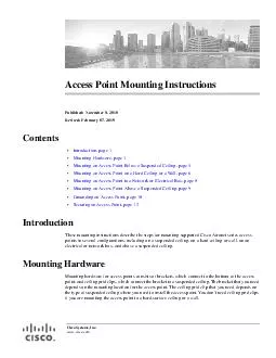
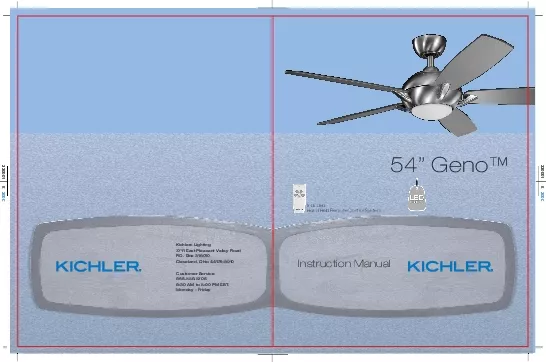
/
34 MOUNTING OPTIONSInstallation listed mounting box then read the Secu 34 MOUNTING OPTIONSInstallation listed mounting box then read the Secu

34 MOUNTING OPTIONSInstallation listed mounting box then read the Secu - PDF document

skylar
skylar . @skylar
Follow
345 views
Uploaded On 2021-08-31

34 MOUNTING OPTIONSInstallation listed mounting box then read the Secu - PPT Presentation

Provide strongsupportRecessedoutlet boxCeilingmountingOutlet boxFig 3Fig 4Outlet boxMAXIMUM 20 ANGLE5Fig 9Fig 10Registration slotCanopyCanopy coverStep 8 Slip the coupling cover canopy cover and canop ID: 873637

step fan screws ceiling fan step ceiling screws light canopy blade outlet motor mounting electrical bracket box fig wall

Share:

Link:

Embed:

Download Presentation from below link

Download Pdf The PPT/PDF document "34 MOUNTING OPTIONSInstallation listed m..." is the property of its rightful owner. Permission is granted to download and print the materials on this web site for personal, non-commercial use only, and to display it on your personal computer provided you do not modify the materials and that you retain all copyright notices contained in the materials. By downloading content from our website, you accept the terms of this agreement.


Presentation Transcript

1 34. MOUNTING OPTIONSInstallation) listed
34. MOUNTING OPTIONSInstallation) listed mounting box, then read the Secure the outlet box directly to the building structure. Use appropriate fasteners and Figures 1, 2 and 3 are examples of different ways to mount the outlet box.NOTE: If you are installing the ceiling fan on a sloped (vaulted) ceiling, you may need a NOTE: Depending on the location you have selected for installation, you may need to Outlet box Provide strongsupportRecessedoutlet boxCeilingmounting Outlet boxFig. 3Fig. 4 Outlet boxMAXIMUM 20° ANGLE 5Fig. 9Fig. 10 Registration slot Canopy Canopy cover Step 8. Slip the coupling cover, canopy cover and canopy onto the downrod.Thread the hanger ball onto the downrod, insert the cross pin through the downrod and Step 9. Lift the motor assembly into position and place the hanger ball into the

2 ceiling Rotate the entire assembly until
ceiling Rotate the entire assembly until the "Check Tab" has dropped into the "Registration Slot" The entire motor assembly should not rotate (left or right) when seated properly.WARNING: Failure to reattach the cross pin and seat the "Check Tab" can cause the fan Set screwsHitch pinRetaining clip Coupling cover 7Fig. 15 Outlet boxCeiling Mounting BracketCanopyCanopy coverScrewsScrews White (neutral)White (neutral)Green or bare copper (ground)White ("AC IN N")White ("to motor N")Ground(green)(Connect to ground wire on Outlet boxBlack (hot)Black ("AC IN L")Black ("to motor L")ReceiverBlue (for light)Blue (for light)Black (motor) Step 1. Tuck all the connections neatly into the ceiling outlet box.Step 2. Slide the canopy up to the mounting bracket and place one of the key hole slots over Step 3. Align th

3 e remaining circular hole on the canopy
e remaining circular hole on the canopy with the remaining hole on the Ceiling Adjust the canopy screws as necessary until the canopy and canopy cover are snug. Make sure the "Check Tab" at the bottom of the hanger bracket is properly seated Connect the white wire from the fan to the white wire marked "TO MOTOR N" on the receiver. Step 3. Receiver to Supply Wires Electrical Connections: (Fig. 14) Connect the black (load) Step 4. Connect the ground wire (green or bare copper) from the outlet box to the ground wire on Fan must be installed at a maximum distance of 30 feet from the Hand Held Remote 911. INSTALLING THE LED LIGHT KIT AND GLASS SHADEFig. 19 Screws Glass shadeWire connectorsLED light kitLight plate Before starting installation, disconnect the power by turning off the circuit breaker

4 or Step 1. Loosen the three mounting scr
or Step 1. Loosen the three mounting screws on the inside of the LED light kit. (Fig.18)Step 2. While holding the LED light kit under the fan motor, make the wire connections: Step 3. Tuck the connections neatly into thelight plate. Place the key holes on the LED light kit over the 2 screws previously loosened Step 4. Raise the glass shade against the LED light kit and turn clockwise until snug, (Fig. 19)Fig. 18 Light plateMounting ringScrewsmounting ring attached to the motor shaft and Step 2. Place the key hole slots on the light plate over the two screws previously loosened Turn the light plate until is locks in place at the narrow section of the key hole slots.Tighten both key hole screws and replace the third screw previously removed and tighten 11Fig. 23Fig. 22Fig. 24 NOTE: Turn fan off by Hand He

5 ld Remote Control System and let blades
ld Remote Control System and let blades come to a Speed settings for warm or cool weather depend on factors such as the room size. Use the fan reverse switch, located on the top of the motor housing (Þg. 22), to optimize your DO NOT remove weatherproof cover on reverse switch.Warm Weather Operation: Forward (counter clockwise) A downward airßow creates a Cool Weather Operation: Reverse (clockwise). An upward airßow moves warm air off the Reverse switch 16. SPECIFICATIONSattached to the ceiling fan.ProblemFan will not start.Fan sounds noisy.Fan wobble.Remote control malfunction.Solution1. Check circuit fuses or breakers.2. Check all electrical connections to insure proper contact. CAUTION: Make sure the main power is OFF when checking any electrical connection.3. Make sure the transmitter batteries are i

6 nstalled properly. Positive (+) side fa
nstalled properly. Positive (+) side facing out.4. Insure the batteries have a good charge.1. Make sure all motor housing screws are snug.interior wall of the switch housing. CAUTION: Make sure main power is off.4. Allow a 24-hour "breaking-in" period. Most noise associated with a new fan disappear during this time.5. If using an optional light kit, make sure the screws securing the glassware are tight. Make sure the light bulbs are not touching any other component.6. Do not connect this fan to wall mounted variable speed control(s). they are not compatible with ceiling fan motors or remote controls.7. Make sure the upper canopy is a short distance from the ceiling. It should not touch the ceiling.1. Check that all blade and blade arm screws are secure.2. Most fan wobbling problems are caused when blade

7 levels are unequal. Check this level by
levels are unequal. Check this level by selecting a point on the ceiling above the tip of one of 3. Use the enclosed Blade Balancing Kit if the blade wobble is still noticeable.side) blades can redistribute the weight and possibly result in smoother 1. Ceiling Fans with remote control systems CAN NOT be operated in conjunction with any other control system EXCEPT a basic On/Off wall 2. Make sure the frequency dip switches in the transmitter and receiver have identical settings.3. Make sure the Black Antenna on the receiver is NOT tangled with any other electrical wires and is extended around the inside of the ceiling canopy. 1312kgs13kgs0.650.5278.10 38.00 161106575697.713795.1173100 CFMCFM/WN.W.G.W.C.F. 9. To avoid personal injury or damage to the fan and other items, be cautious when working around o

8 r cleaning the fan.10. Do not use water
r cleaning the fan.10. Do not use water or detergents when cleaning the fan or fan blades. A dry dust 11. After marking electrical connections, spliced conductors should be turned 12. Electrical diagrams are reference only. Light kits that are not packed with the fan 11. SAFETY RULES WARNINGTO REDUCE THE RISK OF PERSONAL INJURY, DO NOT BEND THE BLADE BRACKETS (ALSO REFERRED TO AS FLANGES) DURING ASSEMBLY OR AFTER INSTALLATION. DO NOT INSERT OBJECTS IN THE PATH OF THE BLADES. Special NoticeThis appliance is equipped with a "Wattage Limiting Device" required by the United States Department of Energy. The device has been installed at the factory and can not be removed.Installing Lamps in excess of 75 total watts will disable the unit's light Þxture. If this should happen, you will need to reset the lighti

9 ng Þxture by turning the power off to t
ng Þxture by turning the power off to the ceiling fan and/or light Þxture, reinstalling lamps totaling less that 75 watts and then turning the power back on.1. To reduce the risk of electric shock, insure electricity has been turned off at the circuit 2. All wiring must be in accordance with the National Electrical Code and local 3. WARNING: Suitable for use with solid- state speed controls.4. WARNING: To reduce the risk of Þre, electric shock, or personal injury, mount to 5. The outlet box and support structure must be securely mounted and capable of 6. The fan must be mounted with a minimum of 7 feet clearance from the trailing edge of 7. Do not operate reversing switch while fan blades are in motion. Fan must be turned 8. Avoid placing objects in the path of the blades.WARNINGTO REDUCE T

10 HE RISK OF FIRE, ELECTRIC SHOCK OR PERSO
HE RISK OF FIRE, ELECTRIC SHOCK OR PERSONAL INJURY, MOUNT FAN TO OUTLET BOX MARKED "ACCEPTABLE FOR FAN SUPPORT". 12Fig. 25Fig. 26Screws 1. Choose a location for the Transmitter Wall Pocket. Any location within 30 feet from the Choose a ßat location, using the wall pocket as a guide, mark the wall anchor locations. Install the plastic wall anchors and attach the wall pocket.2. Your transmitter slips into the wall pocket and may be used from this location or 14. INSTALLING THE TRANSMITTER WALL BRACKET MEDLOW 54" GenoTM 10 Fig. 20Fig. 2113. OPERATING INSTRUCTIONSInstall a 9 volt battery included with the Hand Held Transmitter. (Fig. 20) To prevent damage to the transmitter, Restore power to ceiling fan and test for proper operation.A. "LOW", "MED" and "These three buttons are used to set the fan speed as fo

11 llows:LOW = low speedMEDB. The "OFF" but
llows:LOW = low speedMEDB. The "OFF" button:This button turns the fan off.C. The " " button:This button turns the light ON or OFF.12. INSTALLING THE BATTERY MEDLOW BatteryBattery cover 54" GenoTM 8Fig. 16Fig. 179. ATTACHING THE FAN BLADESStep 1. Insert blade bracket through one of the slots from the ywheel. Align holes from Step 2. Repeat steps for the remaining blade bracket.Step 3. Attach a blade to a blade bracket using the screws and ber washers provided. Make sure the blade is straight when set onthe blade bracket. Tighten each mountingStep 4. Raise the ywheel assembly up against the fan motor. Position the ywheel Screws ScrewsFiberwashersScrews Blades Blade brackets Flywheel Flywheel54" GenoTM 6Fig. 11Ceiling mounting bracket Attach safety cableto ceiling joist with Fig. 12Fig.

12 13Code switch ReceiverCeiling mounting
13Code switch ReceiverCeiling mounting 7. ELECTRICAL CONNECTIONSWARNING: To avoid possible electrical shock, be sure you have turned off the power NOTE: The Hand Held Control System is equipped with 16 possible frequency Step 1. Insert the receiver into the ceiling mounting bracket with the ßat side of the Step 2. Motor to Receiver Electrical Connections: (Fig. 14) Connect the black wire 6. INSTALLATION OF SAFETY SUPPORT(required for Canadian installation ONLY)A safety support cable is provided to help Step 1. Attach the provided wood screw and washers to the ceiling joist next to the Step 2. Adjust the length of the safety cable to reach the screw and washers by pulling the NOTE:required for Canadian installations only. It's a 54" GenoTM 4 Fig. 6Fig. 7Fig. 8Mounting screws (supplied with Hook Ceilin

13 g CUL Listed 120V Wires Washers REMEMBER
g CUL Listed 120V Wires Washers REMEMBER to turn off the power before you begin.To properly install your ceiling fan, follow the steps below.Step 1. Remove the decorative canopy bottom cover from the canopy by turning the Step 2. Remove the ceiling mounting bracket from the canopy by removing (and save one Step 3. Pass the 120 volt supply wires from the ceiling outlet box through the center of the Step 4. Attach the ceiling mounting bracket to the outlet box using the screws and washersStep 5. Remove the hanger ball from the downrod assembly by loosening the set Step 6. Loosen the two set screws and remove the hitch pin and retaining clip from Step 7. Carefully feed the electrical lead wires from the fan up through the downrod. ThreadNext, replace the hitch pin and retaining clip. Tighten both set screws.

14 (Fig. 8) DownrodCross pinHangerball Set
(Fig. 8) DownrodCross pinHangerball Set screw Supply wiresDownrod Hitch pinRetaining clipSet screwsSet screws Fig. 5Hanger bracketCeiling Canopy 5. HANGING THE FAN 54" GenoTM 23. PACKAGE CONTENTSUnpack your fan and check the contents. You should have the following items:a. Fan blades (5) b. Canopy & Ceiling mounting bracketHand Held Remote Control SystemReceiver+5 wire nuts1) Mounting hardware:star washers (2), wire nuts (3),2) Blade attachment hardware:screws (17),3) Blade attachment hardware:screws with lock washers (12)4) Safety cable hardware:wood screw, lock washer, ßat washer5) Balance KitPhilips screw driverBlade screw driver 2. TOOLS AND MATERIALS REQUIRED abcdeghfmlijk MEDLOW 54" GenoTM 7711 East Pleasant Valley Road P.O. Box 318010 8:30 AM to 5:00 PM EST, Hand Held Remote Control Sy