/
CONTENTS 1. INTRODUCTION       1 - 32.        PLANNING OF ARTIFICIAL R CONTENTS 1. INTRODUCTION       1 - 32.        PLANNING OF ARTIFICIAL R

CONTENTS 1. INTRODUCTION 1 - 32. PLANNING OF ARTIFICIAL R - PDF document

stefany-barnette
stefany-barnette . @stefany-barnette
Follow
410 views
Uploaded On 2016-07-19

CONTENTS 1. INTRODUCTION 1 - 32. PLANNING OF ARTIFICIAL R - PPT Presentation

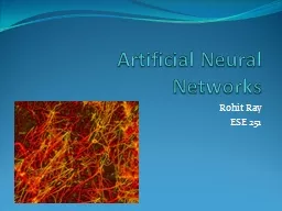
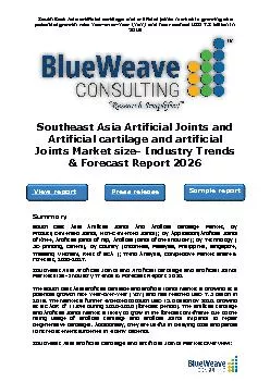
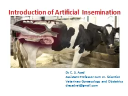
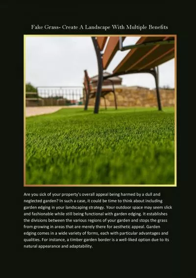
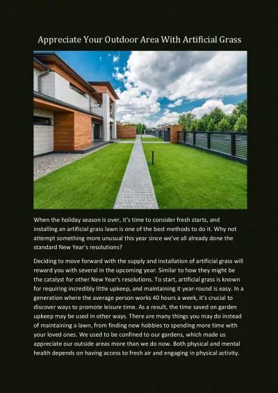
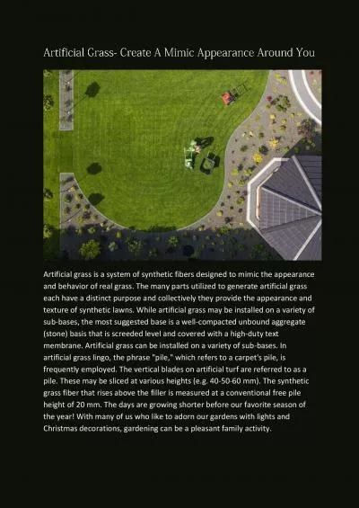
NEW DELHI GUIDE ON ARTIFICIAL REThe artificial recharge to ground water aims at augmentation of ground water reservoir by modifying the natural movement of surface water utilizing suitable civil cons ID: 411214

NEW DELHI GUIDE ARTIFICIAL

Share:

Link:

Embed:

Download Presentation from below link

Download Pdf The PPT/PDF document "CONTENTS 1. INTRODUCTION 1 - 32. ..." is the property of its rightful owner. Permission is granted to download and print the materials on this web site for personal, non-commercial use only, and to display it on your personal computer provided you do not modify the materials and that you retain all copyright notices contained in the materials. By downloading content from our website, you accept the terms of this agreement.


Presentation Transcript

NEW DELHI CONTENTS 1. INTRODUCTION 1 - 32. PLANNING OF ARTIFICIAL RECHARGE PROJECTS 3 - 9 ARTIFICIAL RECHARGE TECHNIQUES AND DESIGN 10 - 324. MONITORING, MECHANISM FOR ARTIFICIAL RECHARGE 33 - 36 5. CASE HISTORIES OF ARTIFICIAL RECHARGE IN INDIA 36 - 75Annexure 1 --Format For Preparation of Artificial Recharge Project Annexure 2 --Planning Artificial Recharge Project -- Checklist Annexure 3 –General Guidelines for the evaluation of Ground Water Recharge Projects with special reference to Basaltic Terrain GUIDE ON ARTIFICIAL REThe artificial recharge to ground water aims at augmentation of ground water reservoir by modifying the natural movement of surface water utilizing suitable civil construction techniques. Artificial recharge techniques normally address to following issues - To enhance the sustainable yield in areas where over-development has depleted the Conservation and storage of excess surface water for future requirements, since these requirements often changes within a season or a period. To improve the quality of existing ground water through dilution. To remove bacteriological and other impurities from sewage and waste water so that water is suitable for re-use. The basic purpose of artificial recharge of ground water is to restore supplies from ssive ground water development. Concept of Augmenting Ground Water Reservoir The sub-surface reservoirs are very attractive and technically feasible alternatives for storing surplus monsoon run off. The sub-surface reservoirs can store substantial quantity of water. The sub-surface geological formations may be considered as "warehouse" for storing water that come from sources located on the land surface. Besides suitable lithological condition, other considerations for creating sub-surface storages are favourable geological structures and physiographic units, whose dimensions and shape will allow retention of substantial volume of water in porous and permeable formations. The sub-surface reservoirs, located in suitable hydrogeological situations, are environment friendly and economically viable proposition. The sub-surface storages have advantages of being free from the adverse effects like inundation of large surface area, loss of cultivable land, displacement of local population, substantiaand sensitivity to earthquakes. No gigantic structures are needed to store water. The underground storage of water would also have beneficial influence on the existing ground water regime. The deeper water levels in many parts of the country, either of natural occurrence or due to excessive ground water development, may be substantially raised, resulting in reduction in lifting costs and energy saving. The quality of natural ground The evaluation of the storage potential of sub-surface reservoirs is invariably based on the knowledge of dimensional data of reservoir rock, which includes their thickness and lateral extent. The availability of sub-surface storage space and its replenishment capacity further govern the extent of recharge. The hydrogeological situation in each area needs to be appraised with a view to assess the recharge capabilities of the underlying hydrogeological formations. The unsaturated thickness of rock formations, occurring beyond three meters below ground level should be considered to assess the requirement of water to build up the sub-surface storage by saturating the entire thickness of the vadose up to 3 m. below ground level. The upper 3 m of the unsaturated zone is not considered for recharging, since it may cause adverse environmental impact e.g. water logging, soil salinity, etc. The post-monsoon depth to water level represents a situation of minimum thickness of vadose zone available for recharge which can be considered vis-a-vis surplus monsoon run off in the The artificial recharge techniques inter relate land integrate the source water to ground water reservoir. Two effects are genearge in ground water reservoir namely - (a) Rise in water level and (b) increment in the total volume of the 2.0 PLANNING OF ARTIFICIAL RECHARGE PROJECTS 2.1 Identification Area The artificial recharge projects are site specific and even the replication of the techniques from similar areas are to be based on the local hydrogeological and hydrological environments. The first step in planning the project is to demarcate the area of recharge. The Project can be implemented systematically in case a hydrologic unit like watershed is taken for implementation. However, localised schemes are also taken to augment ground water reservoir. The artificial recharge of ground water is normally taken in following areas: Areas where substantial amount ound water is inadequate in lean months. In order to plan the artificial recharge schemes following studies are needed surface". Although a distinction is made between infiltration and percolation (the movement of water within the soil) the two phenomena are closely related since infiltration cannot continue unimpeded unless filtrated water from the surface soil. The soil is permeated by noncapillary channel through which gravity water flows downward towards the ground water, following the path of least resistance. Capillary forces continuously divert gravity water into pore spaces, so that the quantity of gravity water passing successively lower horizons is steadily diminished. This leads to increasing resistance to gravity flow in the surface layer and a decreasing rate of infiltration as a storm progresses. The rate of infiltration in the early phases of a storm is less if the capillary pores are filed from a previous storm. There is maximum rate at which water can enter soil at a particular point under a given set of conditions, this rate is called the infiltration capacity. The actual infiltration rate equals the infiltration capacity only when the supply rate rainfall intensity less rate of retention) equals or exceeds. Infiltration capacity depends on many factors such as soil type, moisture content, organic matter, vegetative cover, season, air entrapment, formation of surface seals or crusts etc. Of the soil chtion, non-capillary porosity is perhaps the most important. Porosity determines storage capacity and also effects resistance to flow. Thus infiltration tends to increase with increases infiltration as compared with barren soil because (i) it retards surface flow giving the water additional time to enter the soil (ii) the root system make the soil more pervious and (iii) the foliage shields the soil from raindrop impact and reduces rain packing of surface soil. As water infiltrates soil under natural conditions the displacement of air is not complete even after many hours. Air spaces in the soil and intermediate zones interfere with infiltration as air is not pushed out by the infiltrating water but is gradually absorbed by water. Due to this phenomena infiltration rate may start rising towards a new high after a few days of continuous application of water. Surface conditions have a marked effect on the infiltration process and the formation of surface seals or crusts which forms under the influence of external forces such as rain drop impact and mechanical compaction or through staking reduces the rate of infiltration. Infiltration of water through surface takes place generally over small periods of time and it is the process of redistribution of the soil water that goes on for most of the time and therefore predominates. When rainfall ceases the water wetted during the infiltration process starts to drain with thsoil water conditions during the distribution periods are therefore those that primarily influence plant growth and agricultural husbandry and that also provide the buffer action in hydrologic cycle that the soil water zones has on the transport of water from the soil surface to the ground water aquifer. As such, infiltration is critically inter-linked with the phenomena of water evolution in the vadose zone which includes wetting front In order to know infiltration rates of soils infiltration tests are carried out. Cylinder or flood infiltro-meters are common type of instruments which measure the infiltration as Maps showing ground water potential of different hydrogeologilevel of ground water development. Maps showing chemical quality of The usefulness of all the above interpretative maps is additive, i.e. their conjunctive usage allow greater knowledge and understanding of an area than when a map At this level of hydrogeological mapping of the area few questions should be Whether there is any gap in data on sub-surface geology of the available lithological logs of the boreholes in the area are sufficient to arrive at a correct picture of aquifer geometry of the area. Whether the available data on aquifer parameters is sufficient in case the area shows promise for artificial recharge techniques for deeper aquifers through Injection well etc. Can the available ground water structure serve the purpose of monitoring the effects of artificial recharge Project Aquifer Geometry : The data on the sub-surface hydrogeological units, their thickness and depth of occurrence, and to bring out the disproperties of unconfined , semi-confined and confined aquifers in the area. For surface water spreading techniques the area of interest is generally restricted to shallow depths. The main stress is on knowing whether the surface rock types are sufficiently permeable or not to maintain high rate of infiltration during the artificial recharge. The main purpose of applying geophysical methods for the selection of appropriate site for artificial recharge studies is mostly to help and assess the unknown sub-surface hydrogeological conditions economically, adequately and unambiguously. Generally the prime task is to compliment the exploratory programme. Mostly it is employed to narrow down the target zone, pinpoint the probable site for artificial of geophysical methods is to bring out a comparative picture of the sub-surface litho environment, surface manifestation of such structures, and correlate them Besides defining the sub-surface structure and lithology, it can identify the brackish/fresh ground water interface, contaminated zone (saline) and the area Methods to minimize the clogging effect by suspended matter can be classified Periodical removing of the mud-cake and diciInstallation of a filter on the surface, the permeability of which is lower than that of the natural strata (the filter must, of course, be removed and renewed Addition of organic matter or chemicals to the uppermost layer. Cultivation of certain plant-covers, notably certain kinds of grass. Providing inverted filter consisting of fine sand coarse sand and gravel at the bottom of infiltration pits/trenches are very effective. Clogging by biological activity depends upon the mineralogical and organic composition of the water and basin floor and upon the grain-size and permeability of the floor. The only feasible method of treatment developed so far consists in thoroughly 2.3 Assessment Of Sub-Surface Potential For Ground Water RechargeBased on the hydrogeological and geophysical surveys, the thickness of potential unsaturated zone for recharge should be worked out to assess the potential for artificial recharge in terms of volume of water which can be accommodated in this zone vis-à-vis source water availability. The studies should bring out the potential of unsaturated zone in terms of total volume which can be recharged. The water from stream is diverted to the feeder canal/ditch from which smaller ditches are made at right angles. The rate of flow of water from the feeder canal to these ditches is controlled by gate valves. The furrow depth is kept according to the topography and also with the aim that maximum wetted suwith maintenance of uniform velocity. The excess water is routed to the main stream through a return canal Dendritic Pattern The water from stream can be diverted from the main canal to a series of smaller ditches spread in a dendritic pattern. The bifurcation of ditches continues until practically all the water is infiltrated in the ground. The ditches are excavated following the ground surface contour of the area. When the ditch comes closer to the stream a switch back is made and thus the ditch is made to meander back and forth to traverse the spread are repeatedly. At the lowest point down stream, the ditch joins the main stream, thus returning the excess water to it. 3.1.1.4 Site Characteristics and Design Guidelines Although this method is adaptable to irregular terrain, the water contact area seldom exceeds 10 percent of the total recharge area. b. Ditches should have slope to maintain flow velocity and minimum deposition of sediments. Ditches should be shallow, flat-bottomed, and clMaximum water contact area. Width of 0.3 to 1.8 m. are typical A collecting ditch to convey the excess water back to the main stream channel 3.1.2 Percolation Tanks (PT) / Spreading Basin These are the most prevalent structures in India as a measure to recharge the ground water reservoir both in alluvial as well as hard rock formations. The efficacy and feasibility of these structures is more in hard rock formation where the rocks are highly fractured and weathered. In the States of Maharashtra, Andhra Pradesh, Madhya Pradesh, Karnataka and Gujarat, the percolation tanks have been constructed in plenty in basaltic lava flows and crystalline rocks. A typical design of PT is given in Fig. 3 The percolation 3.1.3 Check Dams Cement Plug nala bunds Check dams are constructed across small streams having gentle slope and are feasible both in hard rock as well as alluvial formation. The site selected for check dam should have sufficient thickness of permeable bed or weathered formation to facilitate recharge of stored water within short span of time. The water stored in these structures is mostly confined to stream course and the height is normally less than 2 m. These are designed based on stream width and excess water is allowed to flow over the wall. In order to avoid scouring from excess run off, water cushions are provided at down streamside. To harness the maximum run off in the stream, series of such check dams can A series of small bunds or weirs are made across selected nala sections such that the flow of surface water in the stream channel is impeded and water is retained on pervious soil/tock surface for longer body. Nala bunds are constructed across bigger nalas of second order streams in areas having gentler slopes. A nala bund acts like a mini eck dam/Cement plug are given in Fig. 4. Site Characteristic and Design Guidelines : For selecting a site for Check Dams/Nala bunds the following conditions may be observed. The total catchment of the nala should normally be between 40 to 100 The rainfall in the catchment should be less than 1000 mm/annum. The width of nala bed should be atleast 5 metres and not exceed 15 metres and the depth of bed should not be less than 1 metre. The soil down stream of the bund should not be prone to water logging and The lands downstream of Check Dam/bund should have irrigable land The Nala bunds should be preferable located in area where contour or The rock strata exposed in the ponded area should be adequately permeable Nala bund is generally a small earthen dam, with a cut off core wall of from nearby watershed can be diverted with some additional cost and the tank can be made more efficient. Such an effort was ma The existing capacity of the tank of 350 TMC was never utilised after its construction. This could however be filled by stream diversion from adjacent watershed. 3.1.7 Dug Well Recharge In alluvial as well as hard rock areas, there are thousands of dug wells which have either gone dry or the water levels have declined considerably. These dug wells can be used as structures to recharge (Fig 6 & 7). The ground water reservoir, storm water, tank water, canal water etc. can be diverted into these structures to directly recharge the dried aquifer. By doing so the soil moisture losses during the normal process of artificial recharge, are reduced. The recharge water is guided through a pipe to the bottom of well, below the water level to avoid scoring of bottom and entrapment of air bubbles in the aquifer. The quality of source water including the silt content should be such that the quality of ground water reservoir is not deteriorated. Schematic diagrams of dug well 3.1.8 Recharge Shaft These are the most efficient and cost effective structures to recharge the aquifer directly. In the areas where source of water is available either for some time or perennially e.g. base flow, springs etc. the recharge shaft can be constructed (Fig 8). Following are site characteristics aIf the strata is caving, proper permeable lining in the form of open work, boulder The diameter of shaft should normally be more than 2 m to accommodate more ddies in the well. In the areas where source water is having silt, the shaft should be filled with boulder, good and sand from bottom to have inverted filler. The upper most sandy layer has to be removed and cleaned periodically. A filter be provided before the source water enters the shaft. When water is put into the recharge shaft directly through pipes, air bubbles are also sucked into the shaft through the pipe which can choke the aquifer. The The main advantages of this technique are as follows: - * It does not require acquisition of large piece of land like percolation tanks. * There are practically no losses of water in the form of soil moisture and evaporation, which normally occur when the source water has to traverse the With Injection Well In this technique at the bottom of recharge shaft a injection well of 100 - 150 mm diameter is constructed piercing through the layers of impermeable horizon to the potential aquifers to be reached about 3 to 5 meter below the water level. (Fig.-9) Ideally suitable for very deep water levels (more than 15 meters) Injection well can be with or without assembly The injection well with assembly should have screen in the potential aquifer at least 3 – 5 meter below the water level. The injection well without assembly is filled with gravel to provide The injection well without assembly is very cost effective. Depending upon volume of water to be injected, number of injection wells, can be increased to enhance the recharge rate. The efficiency is very high and rate of recharge goes even up to 15 lps These structures have been constructed at following places. Injection Well Without Assembly Dhaneta, Samana Block, Injection Well With Assembly Dhuri Link drain, Sangrur district, Punjab 3.1.8.2 Lateral Recharge Shaft Ideally suited for areas where permeable sandy horizon is within 3 meter below ground level and contiCopious water available can be easily recharged due to large storage Silt water can be easily recharged 2 to 3 meter wide and 2 to 3 meter deep trench is excavated, length of which depends on the volume of water to be handled. With and without injection well ( Details of structures already as a means of artificial recharge are comparatively costlier and require specialised techniques of tubewell constructed supported by operation and maintenance to protect the recharge well from clogging. It is an indirect method of artificial recharge involving pumping from aquifer hydraulically connected with surface water, to induce recharge to the ground water reservoir. When the cone of depression intercepts river recharge boundary a hydraulic connection gets established with surface source which starts providing part of the pumpage yield. In such methods there is actually no artificial build up of ground water storage but only passage of surface water to the pump through an aquifer. In this sense, it is more a pumpage augmentation rather than artificial recharge measure. (Fig. 11). In hardrock areas the abandoned channels often provide good sites for induced recharge. Check weir in stream channel, at location up stream of the channel bifurcation, can help in high infiltration from surface reservoir to the abandoned channel when heavy pumping is carried out in wells located in the burried channel. The greatest advantage of this method is that under favourable hydrogeological situations the quality of surface water generally improves due to its path through the aquifer material before it is discharged from the pumping well. For obtaining very large water supplies from river bed lake bed deposits or water-logged areas, collector wells are constructed. In India such wells have been installed in Yamuna Bed at Delhi and other places in Gujarat, Tamil Nadu and Orissa. The large discharges and lower lift heads make these wells economical even if initial capital cost is In areas where the phreatic aquifer adjacent to the river is of limited thickness, horizontal wells may be more appropriate than vertical wells. Collector well with horizontal laterals and infiltration galleries can get more induced recharge from the stream collector wells constructed in seasonal nala beds these can be effective as induced recharge A collector well is a large diameter (4 to 8 m) well from which laterals are driven/drilled near the bottom at one or two levels into permeable strata. The central well is a vertical concrete cassion in precast rings, (wall thickness 0.45 m) sunk upto the bottom of aquifer horizon. The bottom of cassion is sealed by thick concrete plugs. Slotted steel pipes, 9 mm thick, 15 to 50 cm in diameter having open area above 15% and laterally that appropriate places in the cassion. The successive slotted pipes are welded and driven tom of the cassion. The number of laterals is usually less than 16 thus permitting minimum angle of 22 30”, between two laterals. The maximum length of lateral reported is 132 m. and the total length of laterals from 120 injection rates are limited by the physical characteristics of the aquifer. In the vicinity of well, the speed of groundwater flow may increase to the point that the aquifer is eroded, specially if it is made up of unconsolidated or semi-consolidated rocks. In confined aquifer confining layers may fail if too great pressure is created under them. If this occurs, the aquifer will become clogged in the vicinity of the borehole and/or may collapse. In Urban areas, the roof top rainwater can be conserved and used for recharge of ground water. This approach requires connecting the outlet pipe from rooftop to divert the water to either existing wells/ tubewells/borewell or specially designed wells. The urban housing complexes or institutional buildings have large roof area and can be utilising for harvesting roof top rainwater to recharge aquifer in urban areas (Fig 12A). Table shows Table - Availability of Rain Water through Roof Top Rain Water Harvesting Rainfall(mm) 100 200 300 400500600800100012001400 1600 18002000 Harvested water from Roof top (cum) 20 1.6 3.2 4.8 6.489.612.81619.222.4 25.6 28.832 30 2.4 4.8 7.2 9.61214.419.22428.833.6 38.4 43.248 40 3.2 6.4 9.6 12.81619.225.63238.444.8 51.2 57.664 50 4 8 12 16202432404856 64 7280 60 4.8 9.6 14.4 19.22428.838.44857.667.2 76.8 86.496 70 5.6 11.2 16.8 22.42833.644.85667.278.4 89.6 100.8112 80 6.4 12.8 19.2 25.63238.451.26476.889.6 102.4 115.2128 90 7.2 14.4 21.6 28.83643.257.67286.4100.8 115.2 129.6144 100 8 16 24 324048648096112 128 144160 150 12 24 36 48607296120144168 192 216240 200 16 32 48 648096128160192224 256 288320 250 20 40 60 80100120160200240280 320 360400 300 24 48 72 96120144192240288336 384 432480 400 32 64 96 128160192256320384448 512 576640 500 40 80 120 160200240320400480560 640 720800 1000 80 160 240 3204004806408009601120 1280 14401600 2000 160 320 480 6408009601280160019202240 2560 28803200 3000 240 480 720 960120014401920240028803360 3840 43204800 MONITORING MECHANISM FOR ARTIFICIAL RECHARGE The monitoring of water levels and water quality is of prime importance in any scheme of artificial recharge of Ground Water. The monitoring data speaks for the efficacy of structures constructed for artificial recharge and greatly helps in taking effective measures for Ground Water Management on scientific lines. 4.1 Water Level Monitoring During the feasibility study stage the monitoring of surface water and ground water levels greatly help in identifying the method of artificial recharge. Net work of observation wells is used to study the ground water flow pattern and temporal changes in potentiometric head in the aquifer. The observation well net work during feasibility stage is generally of low well density but spread over a large area with the primary aim of defining the boundary zonation of the aquifer to be recharged and to know the hydraulic characteristics of the natural ground water system. After identification of the feasible groundwater structure the observation well net work is redefined in a smaller area with greater well density. The objective of monitoring system is to study the effect of artificial recharge on the natural ground water system. Depending on the method of artificial recharge and the hydrogeology of the area, the observation well net work has to be designed. The monitoring system of observation well network should be designed specially to monitor impact of individual structures which can further be extended to monitor the impact of group of such structures in the artificial recharge scheme area. The net work should contain observation wells (1) near the center of the recharge facility (2) a sufficient distance from the recharge facility to observe composite effects and (3) near the limit of hydrological boundaries. If the recharged aquifer is overlain by confining/semi-confining layer, piezometers should be installed to monitor the water levels of overlying and Where the surface water bodies are hydraulically connected with the ground water aquifer which is being recharged, it is advisable to monitor the water level profiles of both Surface water and Ground water. The periodic monitoring of Water Levels can demarcate the zone of benefit. In this method a network of observation wells is and following observations are made: - 1. In the zone benefitted, the water levels be observed to the whether the well hydrographs have a flat apex during the time when there is water in the recharge structure 2. Wells situated outside the zone of influence normally show an angular apex for 4.4 IMPACT ASSESSMENT The impact assessment of Artificial Recharge schemes can generally be enumerated as follows: - Conservation and harvesting of surplus monsoon runoff in ground water reservoir Rise in ground water levels due to additional recharge to ground water. In case where continuous decline of ground water level was taking place, a check to this and/or the intensity of decline subsequently reduces. The energy consumption for lifting the water also reduces. The ground water structures in the benefitted zone of artificial structures gains sustainability and the wells provides water in lean month when these were going dry. The domestic wells will become sustainable and many of the areas become The cropping pattern in the benefitted zone will undergo marked change due to additionality of ground water and cash crops will start growing. Orchards which went dry earlier due to ground water scarcity may rehabiGreen vegetation cover may increase in the zone of benefit and also along the structures due to additional availability of soil moisture. The quality of ground water maBesides the direct measurable impacts, the artificial recharge schemes will generate indirect benefit in terms of decease in soil erosion, improvement in fauna and flora, influx of migratory birds, etc. Besides, the social and economic status of farmers of benefitted zone will also substantially improve due to increase in crop Remarks: - Format for preparation of Artificial Recharge Project and Checklist for planning is given in Annexure I and Annexure IIGeneral guidelines for the evaluation of ground water recharge projects with special reference to Basaltic Terrain is gi5.0 CASE HISTORIES OF ARTIFICIAL RECHARGE IN INDIA The artificial Recharge for augmentation of ground water reservoir and to provide sustainability to ground water development. The schemes for artificial recharge are being implemented in different hydrogeological situations. The case histories in Indian context Artificial Recharge For Ground Water Sustainability In Basaltic Terrain - onducted specific studies in an over In some of the percolation tanks, visible seepage varies from 20 to 53% of the volume harvested. This is mainly due to faulty designs. The percolation tanks located over vesicular and fractured basalts have better within 15% of the total storage. Mountain Front Recharge Augmentation For Alluvial Aquifers - The prominent regional aquifer system for Tapi Alluvial basin paralleling Satpura Mountain front is being extensively developed to meet the water requirement of cash crops like Banana and Sugarcane. This has led to decline of water levels of more than 8-10 metres during last 10-15 years. Large number of wells has either gone dry or their yields have declined. There is thus an urgent need to augment the ground water resources of the Tapi alluvial basin. The Satpura Mountain front offers favourable locale to augment ground water reservoir due to the high infiltration capacity of alluvial fans occurring in this zone. The Central Ground Water Board has undertaken artificial recharge studies in one of the watersheds TE-17 in Jalgaon district wherein extensive ground water irrigation for Banana crop has resulted in depletion of ground water resource. The studies undertaken included assessment of surplus monsoon runoff available in the watershed and delineation of potential talus and scree zone locally known as Bazada which offers favourable location for construction of artificial recharge structures. The studies included assessment of the total thickness of unsaturated granular zone above water table to determine the potential of recharge in this zone. The sub surface storage potential of watershed 5 metres below ground level was assessed as 85 Million Cubic Metres (MCM) compared to surplus monsoon runoff of 29.7 MCM. Artificial recharge techniques like recharge through percolation tanks, recharge through existing dug wells, recharge shafts and through injection tubewells were experimented. Some of the existing artificial recharge structures like village tanks were renovated to convert these into percolation tanks and storage capacity of augmented by stream diversion from adjacent watershed. The percolation tanks in Bazada formation of Satpura foothills were found to be highly efficient with efficiency as high as 97% and capacity utilisation going upto 400%. The zone of benefit extended to 5 km with benefited area up to 400 ha. The recharge through existing disused dug wells utilising surplus water from existing canal irrigation system provided encouraging results and after observing this experiment, the local farmers have resorted to dug well recharge through their own efforts providing sustainability to ground water development. Recharge through injection tubewell though feasible is not very effective and efficient compared to other artificial recharge techniques. The studies undertaken by Central Ground Water Board have clearly indicated that the Satpura Mountain front is quite favourable for implementation of a mega artificial recharge project which can utilize the techniques experimented in watershed TE-17 for augmenting the depleting ground water resources of 5.3 Artificial Recharge Experiment For Injection Well Technique In Ahmedabad - Gujarat The Physical Research Laboratory, Ahmedabad and Gujarat Water Resources Development Corporation Limited have jointly conducted an experiment on recharging the deeper confined aquifers around Hansol, near Ahmedabad during 1977. The experiment involved transferring of water from shallow aquifer to the deeper confined aquifer using siphon principle. In this experiment, a shallow tube well (dia : 350 mm) of 21.34 m depth was drilled in west bank of Sabarmati river bed and tapping the shallow phreatic aquifer between 6.04 and 21.34 m below river bed level. An injection well (diameter of 600 mm up to 75 m from ground level and followed by 400 mm to the depth of 240 m) to a depth of 238 m was drilled and developed at a distance of 61.3 m from the source well on the same bank of the river. An observation well to the same depth of 238 m was drilled near the injection well to monitor the response of the aquifer during artificial recharge. These deep wells tap the confined aquifers below 74 m depth which agricultural activities. A schematic diagram showing the arrangement of source well, injection well, connecting siphon pipe and the observation well is shown in Fig. 17). A trial recharge experiment was conducted for 92 days for understanding the response of the aquifer during the recharge in terms of development of recharge cone and dissipation of recharge mound. A stabilised recharge rate of 590 litres per minute (LPM) was observed from 200 minute of the recharge experiment till the end. During the recharge phase, nearly 7.5 million litres of water was recharged into the confined aquifer. 5.4 Artificial Recharge In Mehsana Area And Coastal The Pilot Project on evaluating the technical feasibility of artificial recharge in augmenting the depleted aquifers in the Mehsana area and for controlling the saline ingression in coastal belt of Gujarat was successfully conducted by the Central Ground UNDP and State Ground Water Agencies. After detailed hydrogeological surveys and ground water draft estimation, the alluvial area around Kamliwara in the Central Mehsana was selected for pilot experiments on artificial recharge through pressure injection and surface spreading methods during 1983. The source of water drawn for the artificial recharge through pressure injection test was from the phreatic aquifer below the Sarswati river bed. Since for artificial recharge, the injection water was devoid of silts and other impurities and chemically compatible with the water in aquifer getting recharged. The experimental results did not show any adverse effect of clogging. The pressure injection experiment was conducted continuously for about 250 days with an average injection quantity of 225 cubic meters per day. During the recharge cycle, a rise in water level of 5 meters in the injection well (apparent built up of 11 m) and 0.6 to 1.0 m in wells 150 meters away from the injection well were observed. The higher rate of injection continuously for about 250 days was probably sustained because of contemporaneous withdrawal from the aquifer In Mehsana area, artificial recharge experiments through spreading method were also conducted using canal water. A spreading channel of 3.3 meters width, 400 m length with 1 in 1 side slope was constructed and in which the canal water was fed for 46 days. The recorded build up in water level of 1.4 to 2 m. was observed up to 15 m from the recharge channel and about 20 cm at distance of 200 m. The recharge rate of 260 cubic meters per day was estimated using an infiltration rate of 17 cm/day. Dissipation in recharge mound (1.42 m) was observed in 15 days. Another experiment using a recharge pit (1.7 m x 1.7 m x 0.75 m) to study the feasibility of recharging the shallow aquifers was conducted at Dabhu in Central Mehsana area. Canal water was used for the experiment and the pit was covered to prevent dust deposition and evaporation losses. During the recharge phase of was effected at the rate of 17.3 cubic meters per day with an infiltration of 0.5 m/day. A rise of 4.13 m in water level was observed at a distance of 5 meters from the recharge pit. Both these recharge methods were Artificial recharge through pressure injection technique was tried on a pilot scale using ground water from phreatic aquifer for a short period in the Mehsana alluvial aquifers. The source well was located in the injection well at distance of 130 meters by 10 cm pipeline. On-line flow meter and pressure gauge were fitted to monitor the flow rate and cumulative quantity and to record the pressure developed during injection experiment. The injection recharge experiment was conducted with 8 litres per second (LPS) rate for about an hour. The injection rate was increased to 12 LPS and the test was continued for 90 minutes. A drastic reduction in September 15. The daily rainfall varied from 1 mm to 175 mm. The number of rainy days in June, July, August and September were 1,8,6 and 9 days respectively. The water harvesting structures received around 2 fillings and total quantity infiltrated amounted to . This indicates that even during low rainfall years, ground water can be g structures. The Fig. 19 gives the details of ground water harvesting structures in Moti Rayan Area. The water Technology Centre, Tamil Nadu Agricultural University has studied existing 10 percolation tanks in Coimbatore district of Tamil Nadu State for economic evaluation. Eight percolation tanks in Coimbatore taluk and two in Avinashi taluk of Coimbatore district were selected and studied. The study indicate that the total number of wells benefitting from percolation ponds during 1988-89 was 36 out of the 258 wells (14%). The total area benefitted due to these 36 wells was only about 14.4 ha. The direct _______________________________________________________________________________________Pond. No. Total No. of No. of wells Zone of Additional Average benefitted influence area benefitted net income ______________________________________________________________________________________ 2 36 6 0.3 2.4 2736 3 25 3 0.4 1.0 2251 The poor performance of these percolation tanks during the study period was attributed to inadequate rainfall and poor location of the percolation ponds. The districtwise distribution of the benefitted wells had indicated that 39 per cent of the wells as an important parameter in determining the benefits due to percolation ponds. Considering the overall physiographic, hydrogeological, hydrological, demographic and socio-cultural set up of the Nagpur Metropolitan Region, following schemes are feasible for ground water augmentations. a. Roof top rainwater harvesting. b. Run off rainwater conservation. ground water quality has improved 5.10 Artificial Recharge To Ground Water In N.C.T. Delhi In urban areas, dependence on ground water is high, resulting in depletion of ground water resource. This necessitates replenishment of artificial recharge by rainwater harvesting conserving local surface runoff. The CGWB has initiated pilot projects in Jawahar Lal for artificial recharge experiments. In J.N.U. and I.I.T. comprising of 5 micro watersheds, 0.46 Million Cubic Meters (MCM) storm water was going waste which could be stored in purpose-built structures and ultimately recharge the depleted aquifers. Four check dams were constructed on rivulets and sixteen piezometers were established to monitor the impact of artificial recharge on ground water regime. The storage capacity of 49,000 Cubic Meters was created in these dams and 1,25,000 Cubic Meters water had already been recharged to the aquifer. Rise of water level maximum upto 4 m has been observed. Apart from sustainable yield of tubewells and more vegetation cover around the check dams. The efficiency of check dams is around 98% (Fig. 22 and 23). 5.11 Rain Water Harvesting In Chennai City, Tamil Nadu Chennai being a coastal city, is always under threat of seawater intrusion along the coast, if more fresh water is extracted. Indiscriminate extraction in Minjur - a coastal area along the North Sea coast of Chennai, has been spoiled because of over exploitation. The Metrowater is now taking up serious efforts to disseminate Rain Water Harvesting techniques to the citizens of Chennai. In the process, it has issued notifications to the builders who are constructing complexes with 1+3 floors to implement the Rain Water Harvesting measures. Chennai City receives rainfall ranging from 1100 to 1200 per annum. As per statistics, a house on one ground plot (223 sq.m.) gets about 700 litres of water a day by rainfall. Even in the case of multi-storied flats, where the effective space of per resident may be as small as 50 sq.m. , the rainfall corresponds to an amount of about 100 to 150 litres per day. The examples of the step taken in Chennai city are given in Fig. 5.12 Rain Water Harvesting in the President’s Estate, New Delhi President’s Estate having 1.20 sq.km. is located on the Northern flank of Delhi ridge. Excessive ground water development has resulted in ground water decline in the range of 6-13 m. Four metre thick aquifer has become desaturated over an area of 0.7 sq.km. The artificial recharge in the Estate is being done through two dried dug wells, one injection well, one vertical recharge shaft, two recharge trenches with injection wells. more than 11 m and area is experiencing continuous decline of water level at the rate of 30 cm/yr. The presence of clay at shallow depths does not allow surface water to seep naturally into ground water reservoir. To artificially recharge stagnant water in depressions recharge shafts piercing through impermeable clay horizons are being constructed (Fig.- 27). Rise in water level in 500 ha is expected to be around 1.12 m. 5.18 Roof Top Rainwater Harvesting and artificial recharge in Deputy Commissioner Office, Faridabad, Haryana The heavy withdrawal in the vicinity of Faridabad town has caused decline of water levels, which is around 48 cm/yr. The present stage of ground water development in Faridabad block is 90.4%. In the scheme, rain water collected from rooftop and paved area of Deputy Commissioner’s Office will be used for recharging ground water which otherwise goes as runoff. Expected recharge to the ground water is around 2350 cum. 5.19 Artificial recharge to ground water in NSG Campus, Manesar, District Due to heavy withdrawal of ground water in the campus there is steep decline in water level with the rate of about 40 cm per year causing failure of existing tube wells. Gabbion structures are proposed to arrest surface runoff which will seep naturally. Besides this, treated sewage water will also be recharged to ground water through vertical 0.66 mcm water will be recharged. 5.20 Artificial recharge to ground water Golden Temple, Amritsar City, Punjab The Golden Temple Sarovar is filled with canal water and water is pumped out regularly in the sewage drain. In the town water levels are declining at the rate of 0.50 m/yr. due to heavy pumping of ground water. Sarovar water which is being discharged into sewage drain will be used to recharge ground water (Fig.-28). It is estimated that water available for recharge is 0.448 mcm/year. Expected rise in water level in 500 ha will be 0.45m/year. 5.21 Roof Top Rain Water Harvesting and artificial recharge in Kheti Bhavan, Amritsar, Punjab The water supply in Amritsar city is based on ground water which has resulted in Around Kheti Bhavan there has been decline of water level at a rate of 0.50 m/year. A substantial rainfall runoff from rooftops of building constructed is not only going waste but also damaging the roadaround 304 cum is be utilized for recharging the depleted ground water reservoir. provided. Annual water available for recharge is 4.79 mcm. Rise in wais expected to be 0.77 m/year. 5.27 Artificial recharge through excess canal water Dhanetha, Samana Block, Patiala District, Punjab In Samana block the water levels are continuously declining at a rate of 0.35 m/year from 1973 to 1998 and the stage of ground water development is 88%. It is proposed to utilize spare water of Choe No. 1 of main Bhakra Canamid-October to mid-December and mid-February to mid-April when there is no demand of water for irrigation for artificial recharge to ground water. Four Lateral shafts with injection wells and five vertical shafts with injection wells are being constructed for water level in 500 ha will be 2.91m/year. 5.28 Roof top Rain Water Harvesting in Palampur Town, District Kangra, Himachal Pradesh In Palampur town ground water recharge is getting reduced due to urbanization and channelization of the drainage system. A substantial rainfall runoff from the roof top is not only going waste but also damaging the roads and other structures. The run off from rooftop of IPH building will be collected and recharged to ground water by constructing a recharge well. The water will be recharged into the aquifer existing between 12-30 m ated that 576 cu.m. run off water is available for recharge. 5.29 Artificial Recharge in Naker Khad, Renta-Dhawala Village, Tehsil Dehra, District Kangra, Himachal Pradesh The holy town of Jawalamukhi is experiencing water shortages during summer months. Presently water supply to the town is by 12 percolation wells. In order to harness the surplus runoff in the Khad artificial recharge scheme is proposed to provide sustainable yield to the existing wells during summer months. It is proposed to construct a check dam of 1.85 m height and about 16 m in length across the Khad. Total runoff available for recharge is 120 mcm. 5.30 Artificial Recharge in Sikheri, Mandsaur Block, Mandsaur District, Madhya In Mandsaur block, depletion of water levels is taking place due to over development of ground water. Water levels have declined in the range of 1.25- 4.60 m in last 20 years. Level of ground water development is abou 5.35 Artificial recharge to ground watThe stage of ground water development (85%) in Hoogli district is very high. In Pandua block the river Dhusi is one such stream which is connected with river Gangur through a 5 km long channel. Almost entire stretch of the channel has been silted particularly there is no flow except during peak monsoon. Average depth to water level is 16 m.bgl. It is proposed to de-silt the channel to augment ground water recharge. Artificial recharge to ground water in Khatura Bangar, North 24 Parganas, The status of development of the ground water (80%) in the district of North 24 parganas is quite high. The district has considerable area of water bodies like tanks, beels, rivers, bangar etc. Most of these water bodies have been silted up. Due to which the reservoir capacity has decreased and recharge through the water bodies have been minimised. It is proposed to enhance the recharge rate by de-silting these water bodies. This will result in rise in the water levels in the area. 5.37 Artificial recharge to ground water In Purulia district cropping intensity is very high (116%). The Irrigation is from surface and ground water resources. Principal rock types are Archean gneiss having 15 – 20 m weathered mantle. Depth to water level varies from 4.00 to 11.00 m bgl. The water level fluctuation vary from 1 to 5 m. The area has moderate to high slopes and bulk of rainfall is lost due to high run-off. Different types of artificial recharge structures such as g minor irrigation tanks and contour bunding are being constructed. The implementation of these schemes will store the excess monsoon run off on the surface which other than supplying water for irrigation will also recharge the shallow unconfined aquifer to create additional sub-surface storage for fu5.38 Artificial recharge to ground water in Mainpura, District Jhunjhunu, Due to excessive withdrawal of ground wathe area has experienced sharp decline in water level to the tune of 7.1 m in last 13 years and average decline in ground water level is 0.54 m /year. The stage of ground water development is 118.76 % in alluvium & 180.43 % in quartzite. The catchment of Kantli river is 4667.8 Sq. Km and runoff availability is 93 MCM. For utilising the some part of the available runoff for augmentation of ground water resources, one sub surface barrier of 0.8 m. height, 2.75 m depth & 89 m long and three gravity head inverted wells of 1.2 m dia & 10 m. depth are being constructed FORMAT FOR PREPARATION OF ARTIFICIAL RECHARGE PROJECTBase Information of Problem Area 1. Location State District Block Basin/Sub Basin/Watershed Lat. & Longitude Area Extent No. of Villages/Towns 2. Population (i) Human - Urban & Rural Livestock 3. Land use (i) Cultivable & Non-cultivable Area Forest 4. Agriculture (i) Soil Type, thickness and extent (ii) Cropping Pattern (iii) Area under irrigation (a) Surface water (b) Ground water 5. Climate (i) Type of Climate (a) Humid (b) Sub-Humid (c) Arid (d) Semi-arid (ii) Rainfall (a) Average annual (b) Rainfall Distribution (c) No. of Rainy days (d) Temperature (e) Humidity (f) P.E.T. (g) Wind 6. Topographic Features (i) Elevation range (Maximum, Minimum & General) (ii) Landform (a) Hilly Area (b)Highly Dissected Platea Moderately Dissected Plateau (d) Foot Hill Zone Piedmont Zone (f) Valley Slopes (g) Plain Area (h) Sand dune Area (i) Delta Region (j) Coastal Plains (k) Karstitic Terrain (b) Period of Shortage (c) Location of deficit areas (ii) Quantity Problem (a) Control of Sea Water Intrusion (iii) Special Problem (a) Control of Land subsidenc (b) Waste water reclamation through SAT System. 12 Source Water Availability For Artificial Recharge Purpose: ______________________________________________________________________________________ Source Location Quantity Period of Physical Availability & Chemical Quality ______________________________________________________________________________________ Rainfall River Canals Reservoirs Municipal Waste Water ______________________________________________________________________________________ 13.Sub-surface Potential for (i) Thickness of un-saturated zone Ground Water Recharge. (below 3 mbgl). (ii) Total runoff in the catchment (iii) Committed flow….. (iv) Surplus available for recharge. B. Guidelines for Action Plan Identify the data gaps in base information and carry out necessary investigations using the various investigation techniques. Using base data on topography, rainfall, hydrogeology, aquifer situation land source water availability, identify the methods which may be suitable. With reference to the local conditions of the area, further identify the most appropriate techniques of artificial recharge suitable at various sites/locations. . Determine the number of each type of artificial recharge structure needed to achieve the quantitative targets. For individual structure at different locations, finalize the design specifications. 6. Finalize the design of the conveyance system required to bring the source water to the recharge site and the treatment required. Plan the required Monitoring System to evaluate the efficiency of Recharge Scheme. 8. Evaluate the economic feasibility of the Artificial Recharge Project. Have the following investigations been carried out? a) Foundation conditions of percolatioSub-surface strata conditions for Recharge wells, underground dams Spill way design Material Survey Soils for impervious, semipervious, pervious zones of surface/sub-surface iles/Pea (for wells) Cement Steel/Steel pipes/SlotHave the land acquisitions required for structures, inundation, and source water supply channel/pipe line been decided? Has the Mode of acquisition of land been discussed? Has the final location of each structure been decided? Has the lay out of structures been marked out? dual structures been finalised ? for timely construction. the work been identified? Have the yearwise requirement of funds been worked out? Has approval of Finance Department been obtained? Provision made? GENERAL GUIDELINES FOR THE EVALUATION OF GROUND WATER RECHARGE PROJECTS WITH SPECIAL REFERENCE TO BASALTIC TERRAIN The increasing demand for water in the country has brought forward the realisation that the underground reservoirs formed by the aquifers constitute invaluable water supply sources as well as natural water storage facilities. The planned augmentation of water storage in the ground water reservoirs by suitable recharge techniques is useful for reducing over-draft, conserving surface runoff and increasing available ground water supplies. Recharge may be incidental, when it is a by product of normal land and water utilisation measures and planned when the work is carried out with the sole objective of augmenting ground water storage to improve water availability or impact of floods or preventing/stopping sea water intrusion. Ground water recharge techniques have been developenumber of experimental projects implemented with diverse objectives. Whereas the aim of majority of the projects was to augment ground water storage by utilizing surplus rainy season flows or the waste waters; projects for beneficiation of wasurface waters for subsequent use and stopping land subsidence were quite common. In India, the applicability of technologies to tropical conditions has been evaluated through a number of studies conducted by Central Ground Water Board and the State Ground Water The experiences so gained form the base of this note to serve as guide for the evaluation of recharge schemes, now being conceived on a large scale in the States, before their sanction and implementation in order to derive the maximum returns on investments. Whereas the main considerations will be the technical criteria, the expected financial benefits can altogether not be lost sight of. It is, therefore, recommended that the rate at The objectives of recharge schemes are generally the following: To augment the ground water resources. To store the surplus surface water particularly during the flood periods for future To retard the surface run off resulting in lowering of flood peak, conserving the soil by reducing soil erosion and improving the soil moisture retention for longer To improve the quality of water stored. When the source water passes through the soil profile during the process of recharge, the soil mantle acts as membrane to the To conserve thermal energy. CONSIDERATIONS FOR GROUND WATER RECHARGE PROJECTS General Considerations:Water availability. Hydrologic characteristics of the aquifers such as capacity to store, transmit and yield water. Economic viability. Water Spreading Surface channels/Trenches Groundwater dams GENERAL SUITABILITY OF RECHARGE METHODS Lithology Topography Type of Structures Feasible. Alluvial or hard Plain area or Spreading pond, Rock upto 40 m depth. gently Groundwater dams, Undulating irrigation tanks, check area. dams, percolation tanks, unlined canal systems. Hard rock down to Valley slopes Contour bunds, 40 m depth trenches Hard rocks Plateau Recharge ponds Regions Alluvial or Hard Plain area Injection wells, rock with confined or gently connector wells. Aquifer (40m depth) undulating area. -do- Flood plain -do- deposits Hard rock Foot hill Farm ponds, recharge Zones trenches. Hard rocks or Forested area Ground Water Dams. Alluvium e. Topographical and Physiographic considerations for suitability of Recharge Broad features for consideratiTopographic Areas Feasible Methods Plateau Area Western Ghats Pits and shafts Highly Dissected Narrow areas Shafts feasible locally Plateau slopes flanking hill (Gradients of ranges and 1 in 10 and more) Ghats Moderately dissected Large Tracts Contour and Nala Plateaus, foot hills between inter- bunds, and piedmont regions basin percolation tanks (Gradients between) divides, small recharge basins, 1 in 10 to 1 in 100) plateaus and ground water dams, etc. valley floors. (Conservation structures) Low lying valley Valley floors Water spreading, recharge areas (Gradients of of rivers basins and ground water 1 in 100 to 1 in 500) Godavari, dams (Conservation Bhima, Nira, structures). Krishna and their tributaries. Hydrogeological 1. Hydrogeological map of Project site accom- Considerations Hydrological Parameters: Hydraulic conductivity of the aquifer being recharged. The objective of recharging is to spread the water in comparison to fine clay/matrix. Black cotton soil derived from lava flow covering extensive area is clayey and highly calcareous and would impede Phreatic aquifers will receive recharged water more easily than confined systems.reous material filling the vesicles, cavities and joints can subsequently be dissolved by recharged water. This tends to accelerate the recharge rate. Unsaturated rock in the zone will contribute to accelerated recharge. of Aeration upto unsaturated zone. free from thick clay beds. In favourable conditions vesicular and fractured basalt are expected to attain a recharge @ 10% - 15%, whereas in non-favourable physiographic locales underlain by massive basalt, the rate may be Quantitative assessment of ground water system. Post-Recharge Ground Water Balance of Aquifer system. Techno-economic (a) Technical option for various types of feasibility Estimates and costs (v) Cost estimates. h. Financial Analysis Cost of Projects shaCost of Recharge Scheme Cost of supplying the recharged water to i. Assessment of benefits Economics of the investment be given in detail to justify the investment. However, this may not have much relevance when the water is required for drinking purpose since this will be a public responsibility of a welfare State. In case the recharge water is to be used for irrigation the cost benefit ratio be worked out considering pre - and post - development incomes. Net - Pre - Project Income Net - Post - Project Income Net Incremental Income (B - A) = C Cost of Investment Cost of recharge facility BC Ratio, FRR and IRR to be evaluated and considered as per Government