/
Overview of proposed LC-optimized PHY Overview of proposed LC-optimized PHY

Overview of proposed LC-optimized PHY - PowerPoint Presentation

susan
susan . @susan
Follow
66 views
Uploaded On 2023-06-21

Overview of proposed LC-optimized PHY - PPT Presentation

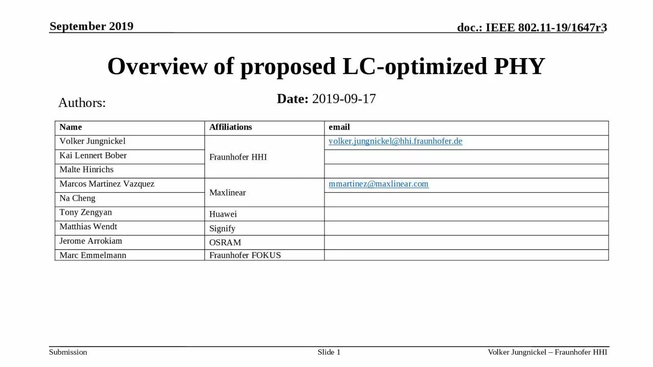
Date 20190917 September 2019 Authors Slide 1 Abstract This contribution presents a summary of new features of the proposed LCoptimized PHY for TGbb Introduction Adaptive bitloading ID: 1001327

optimized phy 802 slide phy optimized slide 802 bandwidth baseband distributed mhz mimo 11ax ieee org dcn 00bb 200

Share:

Link:

Embed:

Download Presentation from below link

Download Presentation The PPT/PDF document "Overview of proposed LC-optimized PHY" is the property of its rightful owner. Permission is granted to download and print the materials on this web site for personal, non-commercial use only, and to display it on your personal computer provided you do not modify the materials and that you retain all copyright notices contained in the materials. By downloading content from our website, you accept the terms of this agreement.


Presentation Transcript

1. Overview of proposed LC-optimized PHYDate: 2019-09-17September 2019Authors:Slide 1

2. AbstractThis contribution presents a summary of new features of the proposed LC-optimized PHY for TGbb.IntroductionAdaptive bitloadingDistributed MIMOHigher bandwidthEasy implementationIntegration of 11ax with LC-optimized PHY Slide 2

3. Slide 3Bit-interleaved coded modulation (BICM) is the concept behind all existing 802.11 PHYs. In RF channels, BICM works well. BICM creates redundancy. Then it permutes bits randomly over all the subcarriers. In a rare fading event, lost bits can be repaired by the soft-decision FEC.1. Introduction: How 802.11 RF PHYs workRF

4.

5. Limitations of 11ax for LCLimitationsAdaptive bitloading is not supportedBandwidth is limited to 160 MHzMIMO is limited to 8 antennasNew interface to LC frontend is neededMaking 11ax useful is certainly important step for LCBut LC should not be limited by 802.11 PHY developed for RFLight is a new wireless medium Short-range, more directive, bidirectional, networked, less interfered LC needs a dedicated PHY to overcome the above limitations.

6. Slide 6LC channel may be 1st order low-pass, due toNLOS propagation [1]Low-power LED driver characteristics [13] Assume 100 MHz baseband and 20 MHz cut-off due to LED driver or channel80% of the bits fall into a fade. BICM operation will basically fail. Replace BICM by adaptive bitloading.2. Why adaptive bitloading?LCdoc. 19-1208r0

7. Slide 7Simulation results for LC-optimized PHY are available in two contributions 1) Preamble, Header and Payload w/o bitloadinghttps://mentor.ieee.org/802.11/dcn/19/11-19-1054-02-00bb-simulation-results-for-lc-optimized-phy-proposal.pptx 2) Dedicated comparison w/o and with bitloadinghttps://mentor.ieee.org/802.11/dcn/19/11-19-1566-03-00bb-simulation-results-with-bit-loading-for-the-lc-optimized-phy.pptxResults

8. Slide 8LC is envisioned as a dense networkOne LC frontend covers few meters spot areaClassical handover concepts are obsolete, taking realistic mobility into accountCentralized AP, distributed LC frontends serve LC Non-AP STAs Large distributed multiuser MIMOSTAs communicate with a subset of frontends LC and RF AP could be co-locatedRF to provide coverage, LC to add capacity3. Why distributed MIMO?LC APFronthaulLC frontendLC Non-AP STA

9. Slide 9[2][2] Kai Lennert Bober, „Performance Evaluation of a Coordinated Visible Light Communication Network“, Master Thesis, TU Berlin, Germany, 2018

10. Slide 10With distributed MIMO, blind spots for communication almost disappear!Distributed MIMO enables consistent system-level performance for LC, similar to what is intuitively expected from the illumination level.

11. Slide 11LC-optimized PHY adds frequency-multiplexed pilot symbols in optional fields, see doc. https://mentor.ieee.org/802.11/dcn/19/11-19-1053-02-00bb-lc-optimized-phy-proposal-for-tgbb.pptxHow LC-optimized PHY supports distributed MIMO?SISO = single-input single-outputMIMO = multiple-input multiple-output SHR = Synchronization header CE = Channel estimationPHR = Physical layer headerHCS = Header check sequence PSDU = PLCP Service Data UnitPLCP = Physical layer convergence protocolPreambleCEsymbolsSHRPHY headerHCSMIMO CE symbolsPHRPSDUPHY payloadSISOoptional MIMO

12. Slide 12Frequency-time multiplexed MIMO RSMIMO RS use a comb of equally-spaced subcarriers. A cyclic shift in the frequency domain identifies each LED. One comb is reserved for noise estimation.The channel is interpolated between non-zero subcarriers, see [11] in doc. 11-19/1053r2.Classical frequency reuse schemes can be applied for pilot assignments to LEDs.

13. Slide 13SoA LC uses high-power LEDs1-10 MHz bandwidth, due to large areaLED bandwidth can be improved by Using infrared as opposed to white LEDsSophisticated LED driver designs: High bandwidth needs more energyVertical cavity lasers (VCSELs) are widely used in cell phones. VCSELs have higher bandwidth due to stimulated emission: 1 GHz and moreVCSEL arrays offer it altogether: High power, high bandwidth and low power4. Why higher bandwidth?doc. 11-19/0916r1

14. Slide 14LC-optimized PHY is based on the home networking standard G.hn. G.hn uses one silicon for multiple media: Powerline, phoneline, coax and plastic optical fiber (POF).For the new LC standard G.9991 the coax profile has been selected.. The coax profile makes scaling to higher bandwidth straight forward, e.g. through the use of carrier aggregation. The concept is discussed in G.hn2 project. How LC-optimized PHY enables higher bandwidth? 200 MHz 200 MHz 200 MHz 200 MHz 200 MHzfrequency

15. LC modulation starts at DC up to some maximum frequency.LC needs a real-valued baseband signal.Fixed (incl. home) networking media are very similar. Baseband chips can be easily reused for LC. dataReusing baseband signals from RF is much more difficult, see e.g. 802.11ax.RF has complex-valued baseband up-converted in the same chip to an RF carrier.New external interface is needed for reusing RF baseband signals for LC.Basically, 11ax needs a digital up-conversion to low-frequ. IFBW/2, like in G.hnSlide 155. Why implementation is so easy? LC-optimized baseband chipAFE chipLC frontendLED/VCSELPD

16. Slide 16Ease of implementationFeasibility is proven by several products from at least 3 independent vendors in current market using the LC-optimized PHY.For example, seedoc. https://mentor.ieee.org/802.11/dcn/19/11-19-1208-00-00bb-practical-experiences-in-implementing-an-lc-optimized-phy-proposed-for-tgbb.ppthttps://www.youtube.com/watch?v=066jgai1Fbc

17. Slide 17Switching between PHY modes is common practice in 802.11 MACIt needs a simple common-mode PHY, supporting low energyThis way we can do all the signaling to switch to a more complex PHY6. Integration with 11ax

18. Slide 18References and resources for LC-optimized PHY are outlined in doc. https://mentor.ieee.org/802.11/dcn/19/11-19-1359-01-00bb-lc-optimized-phy-resources.pptxRessources and references

19. Slide 19Straw PollThe proposed LC-optimized PHY will support Adaptive bit loading Distributed MIMOBandwidth up to 1 GHzEasy implementationIntegration with 11axLC-optimized PHY is to be considered as one mode of operation in TGbb.Y / N / A: 9 / 0 / 8