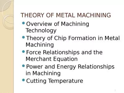
/
2 - Machining Fundamentals – 2 - Machining Fundamentals –

2 - Machining Fundamentals – - PowerPoint Presentation

tatiana-dople
tatiana-dople . @tatiana-dople
Follow
409 views
Uploaded On 2016-05-30

2 - Machining Fundamentals – - PPT Presentation

Measurement Manufacturing Processes 2 IE352 Ahmed M ElSherbeeny PhD Spring2015 Learning Objectives Measure to 164 5 mm with a steel rule Reading an Inchbased Vernier ID: 341980

micrometer vernier scale reading vernier micrometer reading scale thimble gage read measuring gages inch division metric sleeve rule thread

Share:

Link:

Embed:

Download Presentation from below link

Download Presentation The PPT/PDF document "2 - Machining Fundamentals –" is the property of its rightful owner. Permission is granted to download and print the materials on this web site for personal, non-commercial use only, and to display it on your personal computer provided you do not modify the materials and that you retain all copyright notices contained in the materials. By downloading content from our website, you accept the terms of this agreement.


Presentation Transcript

Slide1

2 - Machining Fundamentals –Measurement

Manufacturing Processes - 2, IE-352

Ahmed M El-Sherbeeny, PhD

Spring-2015Slide2

Learning ObjectivesMeasure to 1/64” (.5 mm) with a

steel rule

Reading an Inch-based Vernier Scale

Reading a

Metric-based

Vernier

Scale

Measure

to 0.001”(.02 mm) using

Vernier measuring

tools

Measure to .0001” (.

002

mm) using a

Vernier micrometer

caliper

Use

a

dial

indicator

Employ

the various

helper measuring tools

found in a machine shop

Identify

and use various

types of gages

found in a machine

shopSlide3

CONTENTSSteel Rule

Micrometer Caliper (inch, metric)Vernier

MicrometerVernier Caliper (inch, metric)

Dial Caliper

Universal Bevel Protractor

GagesSlide4

Units of MeasurementThe science that deals with

systems of measurement is called metro

logy. In addition to using US Conventional units

of measure (inch, foot, etc.), industry is gradually converting to

metric units

of measure (millimeter, meter, etc.), called the

International System of Units

(abbreviated

SI). A micrometer is one-millionth of a meter (0.000001 m).

This rule can be used to make measurements in both US Conventional and SI Metric units.Slide5

Reading a RuleYou must first learn to read a rule

to 1/64” and

0.5 mm. Then, you can progress through

1/1000” (0.001”) and

1/100 mm (0.01 mm

)

by learning to use micrometer and Vernier-type measuring tools.

Finally, you can progress to

1/10,000” (0.0001”) and

1/500 mm (0.002 mm) by using the Vernier scale on some micrometers.

Wow!!

1/64

1/1000

1/10000

???Slide6

Different Types of Rules

6” steel rule

Rule with adjustable hook

Narrow rule

Small rules with holderSlide7

Reading the Rule (US Conventional)

This figure shows the different

fractional divisions of the inch from 1/8 to 1/64

The

lines representing the divisions

are called

graduations

.

On many rules,

every fourth graduation is numbered on the

1/32 edge, and every eighth graduation on the

1/64 edge

.

To become familiar with the rule, begin by measuring objects on the 1/8 and 1/16 scales. Once you become comfortable with these scales, begin using the 1/32 and 1/64 scales.

Some rules are graduated in lOths, 2Oths, 5Oths, and lOOths!!

Fractional measurements

are

always

reduced to the lowest terms

. A measurement of 14/16” is reduced to 7/8”, 2/8” becomes 1/4”, and so on.Slide8

Reading the Rule (Metric)

Most metric rules are divided into millimeter

or one-half millimeter graduations.

They are n

umbered

every 10 mm (1 cm)

.

The measurement is determined by

counting the number of millimeters

.

1.0 mmSlide9

The Micrometer Caliper

A Frenchman,

Jean Palmer, devised and patented a measuring tool that made use of

a screw thread

, making it possible to read measurements quickly and accurately without calculations.

It consisted of a series of engraved lines on the sleeve and around the thimble.

The device, called

Systeme Palmer

,

is the basis for the modern

micrometer caliper

.

The

micrometer caliper,

also known as a “

mike

,” is a precision tool capable of measuring to

0.001” or 0.01 mm

.

When fitted with a

Vernier scale

, it will read to

0.0001” or 0.002 mm

.

thimbleSlide10

Types of Micrometers

An

outside micrometer

measures

external

diameters and thickness

,

An

inside micrometer

has many uses, including measuring

internal diameters

of cylinders, rings, and slots.

The range of a

conventional inside micrometer

can be extended by fitting longer rods to the micrometer head.

The range of a

jaw-type

inside micrometer

is limited to 1” or

25

mm. The jaw-type inside micrometer has a scale graduated from right to left.

The divisions on the sleeve are numbered in the reverse order of a conventional outside micrometer.

outside

insideSlide11

Types of MicrometersA

micrometer depth gage

measures the depths of holes, slots, and projections. The measuring range can be increased by changing to longer spindles. Measurements are read from right to left

. Slide12

Types of Micrometers

It measures the

pitch diameter of the thread, which equals the outside (major)

diameter of the thread

minus

the

depth of one thread

.

Since each thread micrometer is designed to measure only a limited number of threads per inch,

a set of thread micrometers

is necessary to measure a full range of thread pitches.

A

screw-thread micrometer

has a

pointed spindle

and a

double-V anvil shaped

to contact the screw thread.Slide13

Reading an Inch-Based Micrometer

A micrometer uses a very precisely made screw thread that rotates in a

fixed nut.

The screw thread is ground on the

spindle

and is attached to the

thimble

.

The spindle advances or recedes from the

anvil as the thimble is rotated.The threaded section has

40 threads per inch

; therefore, each revolution of the thimble moves the spindle

1/40” (0.025”)

. Slide14

Reading an Inch-Based Micrometer

Every fourth division is numbered, representing 0.1

”, 0.2”, etc.

The line engraved

lengthwise

on the sleeve is

divided into 40 equal parts

per inch

(corresponding to the number of threads per inch on the spindle). Each vertical line equals

1/40”, or 0.025

.

The beveled edge of the thimble is divided into

25 equal parts

around its circumference. Each division equals

1/1000” (0.001”)

.

On some micrometers, every division is numbered, while every fifth division is numbered on others.

The micrometer is read by recording the

highest number

on the sleeve (1 = 0.100, 2 = 0.200, etc.).

To this number,

add the number of vertical lines

visible between the number and thimble edge (1 = 0.025, 2 = 0.050, etc.).

To this total,

add the number of thousandths

indicated by the line that coincides with the horizontal sleeve line.Slide15

Example 1

Add the readings from the sleeve and the thimble:

4 large graduations: 4 X 0.100 = 0.400 2 small graduations: 2 X 0.025 = 0.0508 thimble graduations: 8 X 0.001 =

0.008

Total mike reading = 0.458”Slide16

Example 2

Add the readings from the sleeve and the thimble:

2 large graduations: 2X 0.100=0.200

3

small graduations:

3

X 0.025=0.075

14 thimble graduations:

14X 0.001=

0.014

Total mike reading = 0.289” Slide17

Test yourself!

Add the readings from the sleeve and the thimble:

3 large graduations: 3 x 0.100 = 0.3002 small graduations: 2 x 0.025 = 0.0503 thimble graduations: 3 x

0.001 =

0.003

Total mike reading = 0.353”

Read this micrometer:Slide18

Reading a Vernier Micrometer

On occasion, it is necessary to measure more precisely than 0.001”.

A

Vernier micrometer caliper

is used in these situations.

This micrometer

has a third scale

around the sleeve that will furnish the

1/10,000”

(0.0001”) reading Slide19

Reading a Vernier Micrometer

The Vernier scale has 11 parallel lines that occupy the same space as 10 lines on the thimble. The lines around the sleeve are numbered 1 to 10.

The difference between the spaces on the sleeve and those on the thimble is one-tenth of a thousandth of an inch.To read the Vernier scale, first obtain the thousandths reading, then observe which of the lines on the Vernier scale coincides (lines up) with a line on the thimble. Only one of them can line up (

If the line is 1, add 0.0001 to the reading; if line 2, add 0.0002 to the reading, etc.

)

0.2000

0.075

0.0002

0.0120

0.2000

+

0.0750

0.0120

0.0002

0.2872”

10Slide20

Reading

a

Metric-Based MicrometerFollow the same rule:

0.50 mm

5.00

0.50

0.28

Reading is 5.78 mm

30Slide21

Reading a Metric Vernier Micrometer

Metric Vernier micrometers are read in the same way as standard metric micrometers. However, using the Vernier scale on the sleeve, an additional reading of

two-thousandths of a millimeter can be obtained.

7.000

0.500

0.310

0.004

Reading is 7.814 mm

7.000mm

0.500mm

0.310mm

30

35Slide22

Using the Micrometer

The proper way to hold a micrometer: The work is placed into position, and the thimble rotated until the part is clamped

lightly

between the anvil and spindle.

When the piece being measured must also be held, position the micrometer as shown, with a finger in the micrometer frame. Slide23

Some micrometers have features to help regulate pressure:A ratchet stop

is used to rotate the spindle. When the pressure reaches a predetermined amount, the ratchet stop slips and prevents further spindle turning.

A

lock nut

is used when several identical parts are to be gaged. The nut locks the spindle into place. Gaging parts with a micrometer locked at the proper setting is an easy way to determine whether the pieces are sized correctly.

Using the MicrometerSlide24

Vernier Measuring Tools

The Vernier principle of measuring was named for its inventor, Pierre Vernier, a French mathematician.

The Vernier caliper can make accurate measurements to 1/1000” (0.001”) and 1/50 mm (0.0

2 mm).

The design of the tool permits measurements to made over a large range of sizes. It

is manufactured

as a standard item in

6”, 12”, 24”, 36”,

and

48” lengths.

SI Metric Vernier calipers are available in mm, 300 mm, and 600 mm lengths.

The 6”, 12”

sizes are most commonly used.

Standard Vernier caliper

Modern

digital

calipers

Slide25

Vernier Measuring Tools

Vernier calipers can be used to make both internal and external measurements.

Slide26

Vernier Measuring Tools

Height gage

Depth gage

Digital gage

Slide27

Vernier Measuring Tools

Gear tooth Vernier calipers are used to measure gear teeth, form tools, and threaded tools. Slide28

Vernier ScaleSlide29

Reading an Inch-based Vernier scale

Two measuring tools

are available:

25-division

Vernier plates.

It can be read to

0.001”.

Vernier plate is graduated into

40

equal parts.

Each graduation is

1/40” or 0.025.

Every

four division

=

0.1”

50-division

Vernier plates.

It can be read to

0.001”.

Vernier plate is graduated into

50

equal parts.

Each graduation is

1/50” or 0.02.

Every

fifth division

=

0.1”Slide30

25-division Vernier plates

Every

four division

=

0.1”Slide31

25-division Vernier plates

1.0 1.0 +

1x0.1= 0.11x0.025= 0.025

20x.001= 0.020

1.145”

Remember that for a 50-division one, the principle is the same, except that one graduation is 0.050”.Slide32

How to read a 25-division metric-based Vernier scale

Readings on the scale are obtained in units of two hundredths of a millimeter (0.02 mm)

mmSlide33

Test yourself!Read each Vernier:

0.1 mmSlide34

Vernier CaliperSlide35

Dial Calipers

Dial calipers provide direct readings of measurements.

Slide36

Universal Bevel Protractor

50

o

00’

50

o

00’+

0

o

20’

50

o

20’

Check near zero

Degree (°)—

Regardless of its size, a circle contains 360°. Angles are also measured by degrees.

Minute ( ’ )—

A minute represents a fractional part of a degree. If a degree is divided into 60 equal parts, each part is one minute. A foot mark (‘) is used to signify minutes (e.g. 30°15’).

Second ( ” )—

Minutes are divided into smaller units known as seconds. There are 60 seconds in one minute. Slide37

Vernier scale for reading the angle

This Vernier scale allows the angle to be read to an accuracy of about 0.05 degrees.

1- Begin by reading the integer of the angle directly – here, this is 19 degrees. Use the next smallest number below the line pointed-to by the arrow ("1" in the figure shown).

2- Next, the fractional angle can be read using the Vernier. Simply follow the lines across on the Vernier scale (the outside) until you locate the ONE which best lines-up with a line (any line) on the circular inner scale.

19.8 degreesSlide38

GagesGaging

involves checking parts with

various gages. Gaging

simply shows whether

the piece is made

within the

specified tolerances

.

Examples of Gages:

plug gages, ring gages, snap gage, thread gage, and optical gages.

When

great numbers of an item

with several

critical dimensions

are manufactured, it might not be possible

to check each piece

.

It then becomes necessary to decide how many

randomly selected

pieces must be checked to ensure satisfactory quality.

This technique is called

statistical quality control

.Slide39

Plug Gage

Plug gages

are used to check whether

hole diameters

are

within specified tolerances

.

A double end cylindrical plug gage has two gaging members known as

go

and

no-go

plugs

.

The

go plug

should enter the hole with little or no interference.

The

no-go plug

should not fit.Slide40

Ring GageExternal diameters

are checked with ring gages

.

The go and no-go ring gages are separate units, and can be distinguished from each other by a

groove cut

on the knurled outer surface of the

no-go gage

. Slide41

Snap Gage

A

nonadjustable snap gage

is made for one specific size.

An

adjustable snap gage

can be adjusted through a range of sizes.

A

snap gage

serves the same purpose as a ring gage. Snap gages are designed to check

internal diameters

,

external diameters

, or both. There are three general types:

A

dial indicator

snap gage

measures the amount of variation in the part

measurement.

Slide42

Please Visit the following webpageshttp://en.wikipedia.org/wiki/Micrometer

http://www.stefanelli.eng.br/en/index.html (very good)

http://members.shaw.ca/ron.blond/index.html (very good)

http://longislandindicator.com/p7.html

(calibration of gages)