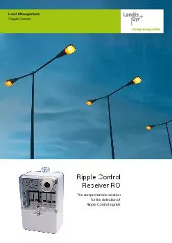
/
HFKQLFDOSHFLFDWLRQRD Ripple Control RC is used for a systems control of current FRQVXPSWLRQLQWKHHOHFWULFDWLRQVVWHPVZLWFKLQJUDWHV HFKQLFDOSHFLFDWLRQRD Ripple Control RC is used for a systems control of current FRQVXPSWLRQLQWKHHOHFWULFDWLRQVVWHPVZLWFKLQJUDWHV

HFKQLFDOSHFLFDWLRQRD Ripple Control RC is used for a systems control of current FRQVXPSWLRQLQWKHHOHFWULFDWLRQVVWHPVZLWFKLQJUDWHV - PDF document

tatiana-dople
tatiana-dople . @tatiana-dople
Follow
484 views
Uploaded On 2014-12-22

HFKQLFDOSHFLFDWLRQRD Ripple Control RC is used for a systems control of current FRQVXPSWLRQLQWKHHOHFWULFDWLRQVVWHPVZLWFKLQJUDWHV - PPT Presentation

5735957347WKH RXWSXW57347UHODV57347ZLOO57347SHUIRUP57347WKH57347SODQQHG57347DFWLRQ5734757355H57361J5736157347SHULRGLFDO57347VZLWFKLQJ RI57347WKH57347RXWSXW57347UHOD57347FKRVHQ57347RU57347DOO57347UHODV57347DUH57347WHPSRUDU57347WUDQVIHUUHG57347WR GH575 ID: 27583

wkh 57347 57359 57361 57347 wkh 57361 57359 57363 dqg 57368 57364 57535 57365 zlwk iru 57360 57355 5hod fdq 7kh duh

Share:

Link:

Embed:

Download Presentation from below link

Download Pdf The PPT/PDF document "HFKQLFDOSHFLFDWLRQRD Ripple Control RC i..." is the property of its rightful owner. Permission is granted to download and print the materials on this web site for personal, non-commercial use only, and to display it on your personal computer provided you do not modify the materials and that you retain all copyright notices contained in the materials. By downloading content from our website, you accept the terms of this agreement.


Presentation Transcript

Technical Speci�cation No. A - 2 • 1 • 70, May 2013 A digital �lter with widely programmable parameters processes the received signal. A microcomputer evaluates received signals and controls all The RCR can react to any well-known command code. The user can choose and �lter width, sensitivity, different time functions and respond to outage and subsequent supply voltage recovery. RCRs can be programmed via Win XP. Every FMX 500 series RCR in its EEPROM stores data used for A special alphanumeric note or code, entered by the user, makes identi�cation of all receivers easy and clear and, with PC support, gives possibility to record e.g. how and when each RCR was programmed last. The memory also stores the FMX 500 RCR series number, production code, date of the last programming, L R Technical Speci�cation No. A - 2 • 1 • 70, May 2013 A combination of a modern microcomputer, EEPROM and modi�able hardware provides for a wide array of functionalities, e. g.:RCR programmability to respond up to three different RC systems, operating on common frequency in time multiplex;Simultaneous operation of both standard RC system and long distance data parametrization system as per DIN 43861, with optional mutual Programmable responses to power or real time outages and recoveries make possible to set the RCR relay to a programmed position in case of power outage or recovery, and in case of time functions being engaged, to continue these, start them over again or stop them, as Broad parametrization of control software properties. The following parameters can be set: number of switching programmes, number of individual programme changes, time step (min/sec) and the activation mode. Also, a learning function can be engaged to modify the control A learning function, with programmability of both signal property to be learned and conditions of its activation;Programmable RCR behaviour setting / modi�cation, includes the shape of input �lter frequency characteristic, receiver sensitivity and Effective �ltration of control signal interference pulses, with programmable parameters;Number of control functions, allocated to each relay, is limited by used EEPROM capacity only;Simply de�ned various time functions that can be engaged, disengaged or synchronized by any command. Each relay can thus also work as a pulser, governed by speci�ed command codes and remaining in either position as programmed, or as a timer, etc.;“Self-learning” function available, e. g. for public lighting or other control (proper function is maintained even if a RC transmitter outage Programmable con�rmation of relay position. If the relay position is tampered with, the RCR will automatically switch to the correct position no Automatic received telegram monitoring in supporting PC. Time stamped monitored telegrams can be saved for later analysis;Veri�cation of RCR functions by internal test execution;TEST button programmability;Telegram receiving can be interrupted after an execution pulse was received;Working PrincipleAfter its amplitude reduction by the input divider, the control signal All information, i. e. command code, control frequency, sensitivity, are stored in the EEPROM data memory. Memory content and thus power voltage 50 Hz. The RCR can be equipped, as per customer The SELFTEST (ST) function that can be activated by pushing the button accessible after removing the terminal board cover, serves RCR relay is connected to external circuits. This button function is programmable. During the ST function, checksum of the de�ned positions, etc). After executing the ST, all relays are set to their original positions. During ST execution, all other RCR functions if “mass programming” is used, activated by pressing the ST button. content or execute the ST function. After the programming is done, or off. The communication adapter secures galvanic separation of made only if the RCR power supply is on. A security code protects Two LED diodes are used for a visual check of work and operation states of the RCR. The yellow LED shows basic RCR states, i. e. real time can be set using an RPC 500 / 590 adapter. This contains and copy adapter real time to the RCR. The RPC 500 / 590 adapter is Technical Speci�cation No. A - 2 • 1 • 70, May 2013 Basic type. This RCR uses a 12 terminal box, has 1 to 4 relays and can be installed into a switchboard using three M5 bolts "triangle" laid out. This RCR module is to be built into the three-phase meter ZPA EMU 300.4U (H), ZE 310.DU or ZE 310.DM, ZE 310.MM with a standard opto-contacts (with switching current of up to 8 A) are led to terminals that are accessible only after removing the terminal box cover. K1 and K4 relays used for switching the meter rates are optron based in the FMX 552 type. Both the contact programming connector and selftest button are accessible only after removing the meter cover. The module is completely (except for the power supply) galvanically separated from the meter.This RCR module is to be built into a single-phase meter ZE 110.DH with a standard opto-interface. It comprises a printed circuit board with output relays and is covered together with the meter. K2 and K3 relay contacts (with switching current of up to 8 A) are led to terminals that are accessible only after removing the terminal box cover. K1 and K4 relays used for switching the meter rates are optron based. Both the contact Technical Speci�cation No. A - 2 • 1 • 70, May 2013 removing the meter cover. The module is completely (except for the power supply) galvanically separated from the meter.connected into the switch board via detachable terminals. There are of up to 6 A). Both the contact programming connector and selftest button are accessible only after removing the RCR cover. Sealing dimensions see below.Type Identi�cation FMX 552 Two Relays + Two Switching Optrons Duration of Real Time BackupBackup Time 64 HoursWith Remote Data ParametrizationTesting Type Identi�cation FMX 5xx Without OptointerfaceWith OptointerfaceTwo Relays ExchangeableOne Exchangeable Relay Assembled, Two Free Duration of Real Time BackupWithout Real Time BackupBackup Time 4 HoursBackup Time 8 HoursBackup Time 16 Hours Backup Time 32 HoursBackup Time 64 HoursWith Remote Data ParametrizationTesting Connection A Technical Speci�cation No. A - 2 • 1 • 70, May 2013 Type Identi�cation FMX 562 Two Relays + Two Switching Optrons Duration of Real Time BackupBackup Time 64 HoursWith Remote Data ParametrizationTesting Type Identi�cation FMX 59x Two Relays ExchangeableDuration of Real Time BackupBackup Time 64 HoursWith Remote Data ParametrizationTesting V Technical Speci�cation No. A - 2 • 1 • 70, May 2013 EN 62 054-11:05, EN 62 052-21:05Nominal Supply Voltage UPermissible Allowance Uof Nominal Supply Voltage UPermissible Allowance fmax. 12 VA capacitiveTime Between Command CodesAmbient Operating Temperaturepermanently 5 A cos φ 1; permanently 2 A permanently 25 A permanently 8 A permanently 6 A Max. Total I25 A to 75 A Max. Total I16 A Max. Total Iinitial relay x 6 A Electric Service Life of Output Relay (max. 6 A)IP 51Number of Terminals in Terminal BoxWorking PositionOperation TypeWeight INFORMATIONseparately. PSION WorkAbout MX terminal parametrization FMX 500/ 590 RCR with PSION WorkAbout MX printed circuit board Version U1;printed circuit board Version U2;S 11 IRRCR with PSION WorkAbout MX terminal;Standard extension 11 thru 16 mms, other Terminal box cover of 1 phase electrometer for Terminal box cover of 3 phase electrometer for Technical Speci�cation No. A - 2 • 1 • 70, May 2013 Technical Speci�cation No. A - 2 • 1 • 70, May 2013 ZPA Smart Energy a.s., Komenského 821, 541 01 Trutnov, Czech RepublicTel.: +420 499 907 111, fax: +420 499 907 497E-mail: zpa@zpa.cz, http.: //www.zpa.cz If so agreed with the manufacturer, the following RCRs can be supplied:To serve local authorities, public lighting, electrical engineering companies, etc., programmed for governing of public lighting including night switch-off intervals, if so required.INSTAATIONNo special maintenance is required during RCR service life. The RCR is to be kept clean after all inspections and repair work, its terminals . All instructions for work with CMOS parts must be observed.WARNING OF RCR AND PACKAGING MATERIAunused products must be disposed off ecologically in line with the Law on Waste.NOTICE OF MANUFACTURERThe product can be used safely. The manufacturer issued the Statement of Conformity as speci�ed in § 13 of Law No. 22/97.In spite of this, however, the manufacturer draws attention to possible risks resulting from incorrect operation or use of the product:Installation and maintenance must be carried out only by trained persons with electrotechnical quali�cations who will tell the customer all the The product must not be used for purposes different than those it was manufactured for.The product must not be wilfully modi�ed to be different than it is speci�ed in the type speci�cation.The product must not work with different voltage, current and frequency than it was manufactured for or must not be professionally modi�ed.The product must be placed and secured in such a way that no unauthorized persons without electrotechnical quali�cations, especially Each time the product is again put into operation, e. g. after a repair, maintenance, complete protection must be secured as well as all It is necessary - during operation of the product - to prevent risks of �re or explosion in case of generated gases, in�ammable liquid vapours The product must not work in such conditions and environment that do not secure safety operation (e. g. installation on the in�ammable base,