/
navigation systems avionics and marine fluxvalve replacemen navigation systems avionics and marine fluxvalve replacemen

navigation systems avionics and marine fluxvalve replacemen - PDF document

tatiana-dople
tatiana-dople . @tatiana-dople
Follow
376 views
Uploaded On 2015-08-29

navigation systems avionics and marine fluxvalve replacemen - PPT Presentation

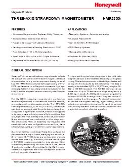
THREEAXIS STRAPDOWN MAGNETOMETERHMR2300r A unique switching technique is applied to the solidstatemagnetic sensors to eliminate the effects of past magnetichistory This technique cancels out the br ID: 118037

THREE-AXIS STRAPDOWN MAGNETOMETERHMR2300r A unique switching

Share:

Link:

Embed:

Download Presentation from below link

Download Pdf The PPT/PDF document "navigation systems avionics and marine f..." is the property of its rightful owner. Permission is granted to download and print the materials on this web site for personal, non-commercial use only, and to display it on your personal computer provided you do not modify the materials and that you retain all copyright notices contained in the materials. By downloading content from our website, you accept the terms of this agreement.


Presentation Transcript

¥Navigation SystemsÑAvionics and Marine¥Fluxvalve Replacement¥Can be Slaved to AHRS System¥GPS Backup Systems¥Remote Vehicle Monitoring¥Unpiloted Air Vehicles (UAVs)¥Strapdown Magnetometer Replaces Bulky Fluxvalves¥Microprocessor Based Smart Sensor¥Range of ¥Readings can Achieve Heading Resolution of 0.02¥Rate SelectableÑ10 to 154 Samples/Sec.¥Small Size: 2.83 in.ÑFits in ML-1 Style Enclosure THREE-AXIS STRAPDOWN MAGNETOMETERHMR2300r A unique switching technique is applied to the solid-statemagnetic sensors to eliminate the effects of past magnetichistory. This technique cancels out the bridge offset as wellas any offset introduced by the electronics. The data isserially output at either 9,600 or 19,200 baud, using the RS-422 or RS-485 standard. The RS-485 standard allowsconnection of up to 32 devices on a single wire pair up to4,000 feet in length. An HMR address can be stored in theon-board EEPROM to assign one of thirty-two unique ID com OPERATING SPECIFICATIONSÑTable 11 Gauss (G) = 1 Oersted (in air), 1G = 79.58 A/m1G = 10E-4 Tesla, 1G = 10E5 gammaTIMING SPECIFICATIONSÑTable 2 6µs citsiretcarahnoitidnoiyainUPSERT)2,1.sgiF(smargaiDgnimiT)DIeciveD=dd(dnammocdd*Pdd*TSRdd*Cdd*)wolebsnoitpecxe(dnammoc99*Qdd*Q99*9..22.2604)04xdd(+2)08xdd(+2)021xdd(+22.32.35.606pyT+2pyT+2pyT+2cesmYALEDT)2.giF(margaiDgnimiT)DIeciveD=dd(dnamoc99*)04xdd(+yT+esmETYBT0069)1.giF(smargaiDgnimiT0029140.125.0cesmPUTRATSgassempU-tratSfotratsotdeilppArewo4esm HMR2300r Timing is not to scale RS-485 and RS-422 COMMUNICATIONSÑFigure 1 GLOBAL ADDRESS (*99) DELAYÑFigure 2 Parameter Selections verses Output Sample RateÑTable 3 LoHi r00; HMR2300r Response 4V 2V1V4V 2V1V TBYTE TRESP StartLSBMSBStop TRESP AAA Bytes r00;(*01P)HMR ID=01Response r00;(XXYYZZVC) AAA Bytes r00;(*99P)HMR ID=00Response r00;(XXYYZZVC) HMR ID=02Response r00;(XXYYZZVC) TDELAY (ID=01) AAA AAA AAA Response r00;(XXYYZZVC) TDELAY (ID=02)TRESP Continuous Reading Period(msec)1015141.53519.69.8 10450/6050/60100/120SampleRate(sps)9600yes19200yes9600yes19200yesASCII Notch(Hz)f3dB(Hz)10 20 100 154 Binary INVALID (1) r00;All inputs must be followed by a , key. Either upper or lower case letters may be used. Tdecimal number between 00 and 99. Device ID=99 is a global address for all units.(2) The ÒÓsymbol is a carriage return (hex 0D). The Ò_Ó symbol is a space (hex 20). The output response will be delayed from the end ocarriage return of the input string by 2 msec (typ.), unless the command was sent as a global device ID=99 (see TDELAYCOMMAND INPUTSÑTable 4A simple command set is used to communicate with the HMR. These commands can be typed in through a standardkeyboard while running any communications software such as HyperTerminal in WindowsD}2 HMR2300r DATA FORMATSThe HMR2300 transmits each x, y, and z axis as a 16-bitvalue. The output data format can either be 16-bit signedcharacters. The command *ddA will select the ASCII formatThe order of output for the binary format is: Xhi, Xlo, Yhi,Ylo, Zhi, Zlo. The binary format is more efficient for a com-puter to interpret since only 9 bytes are transmitted. Thequires 28 bytes per reading. There are limitations on the(see Table 3). Examples of both binary and BCD ASCII out-BCD ASCII Binary Value (Hex)(Gauss)Value High ByteLow Byte30,000753022,50057E415,0003A987,5001D4C0.0000000-0.5- 7,500E2B4-15,000C374-22,500A81C-30,0008AD0Output ReadingsÑTable 5 Y Y Validity =signed high byte, x axis =low byte, x axis =signed high byte, y axis =low byte, y axis =signed high byte, z axis =low byte, z axisValidity =Validity byte is described below=Checksum is the ones complement of r00;carriage return (Enter Key), Hex code = 0Dand will appear as strange symbols. This format is best+ Validity) The Validity byte indicates that the onboard microproces-mode of operation. The various user selectable modes arebyte and associated ASCII character.ZeroAverageAutoValidityReadingsReadingsSet/ResetCharacterbyteoffoffoffO4FoffoffonS offonoffO4FoffononV56onoffoffP50onoffonT54ononoffP50onononW57 Default mode. This mode can be reset using the SP SP The ASCII characters will be readable on a monitor assigned decimal numbers. This format is best when the user r00;carriage return (Enter Key), Hex code = 0DSP =space, Hex code = 20SN (sign) =- if negative, Hex code = 2DCM (comma) =, if leading digits are not zero, Hex code = 2C=Decimal equivalent ASCII digit =SP if leading digits are zero, Hex code = 20INTERFACE CONVERTER TO RS-232ÑFIGURE 3 TD(B)RD(A)SG+12VDCTERM.RS-232 to RS-485B&B Electronics #485PTBRRS-422 Rx-hi 8Tx-lo 3 Gnd 5 Pwr 9J1 Pinconnector+12VDC 2RDTDRDGDRS-232 DATA COMMUNICATIONSThe RS-422 signals are balanced differential signals thatcan send and receive simultaneously (full-duplex). The RS-485 signals are also balanced differential levels but thedifference voltage. That is, when a logic one is beingtransmitted, the Tx line will drive about 1.5 volts higher thanvolts lower than the Hi line. This allows signals to betypically 4,000 feet. These signals are also slew-rate limitedfor error-free transmission. The receiver has a commonmode input range of -7 to +12 volts. The signal connectionsstop reading will occur. If an operator is trying to stopHMR2300r, then the two will produce an erroneouscharacter that will not stop the data stream. The data stream 2 - Tx-hi (RS-422) or Hi (RS-485) for manufacturers use only - 9nc - 7+6.5 to +15VDC power - 5+6.5 to +15VDC return - 3nc - 110 - for manufacturers use only8 - for manufacturers use onlyP1 SocketsPin Assignment(no connect)connected to J1 pin 6Chassis ground+6.5 to +15VDC powerconnected to J1 pin 7(no connect)for manufacturers use onlyP1 Pin#110Pin AssignmentRx-lo (RS-422)Tx-hi (RS-422) or Hi(B) (RS-485)Chassis ground+6.5 to +15VDC returnRx-hi (RS-422)+6.5 to +15VDC power(no connect)J1 Pin#110 HMR ComputerLoHi Z=120WLo (A)Hi (B) HMR ComputerRx-lo Z=120W Tx-loTx-hi HMR2300r BOARD DIMENSIONSÑFIGURE 7All Dimensions in inches TOP-SIDE OF CIRCUIT BOARD ASSEMBLYBACK-SIDE OF CIRCUIT BOARD ASSEMBLY SAMTEC SSQ-105-01-S-D AAA A SAMTEC TSW-105-06-T-D +Z axis(Down) .060 .39 MAXCOMPONENTHEIGHT .12 MAXCOMPONENT ¥The presence of ferrous materialsÑsuch as nickel, iron,turbances in the earthÕs magnetic field that will distort x,¥The presence of the earthÕs magnetic field must be taken¥The variance of the earthÕs magnetic field must be ac-counted for in different parts of the world. Differences in ORDERING INFORMATIONthe earthÕs magnetic field are quite dramatic betweenNorth America, South America and the Equator region.¥Perming effects on the HMR board need to be takenmust be degaussed. The result of perming is a high zeronot degaussed, zero field offset values may result. QUALITY AND ENVIRONMENTAL CONDITIONSÑTABLE 6 APPLICATIONS PRECAUTIONS etemaraP leveLtseTdnadohteMdraoBtiucriCdetnirP.12/1014-CPIrepgerperpdnasetanimal4-RFgnisu,3ssalC,2106-CPIdna1106-CPIotsmrofnoCpihsnamkroWdnaylbmessA.ylevitcepser,3ssalC,016-A-CPIdna,3ssalC,100-DTS-JotsmrofnoCseciveDevitisneScitatsortcelEyranoituacerpdna)DSE(eciveDevitisneScitatsortcelEnasadetaertebllahsr0032RMHehT.ylppallahsgnikramdnagnildnah)FBTM(eruliaFneewteBemiTnaeM.deificepssnoitidnoclatnemnorivneehtrednumuminimsruoh000,52sir0032RMHehtfoFBTMehTedutitlA.IIIerudecorP,1.025dohteM,E018-DTS-LIMrepsedutitlagnidnatshtiwfoelbapacsir0032RMHehTsugnuFdnanoitarepohtobni,dnatshtiwlliwdnaslairetamtneirtun-nonhtiwdetcurtsnocsir0032RMHehT4.805dohteM,E018-DTS-LIMrephtworgsugnufoterusopxe,snoitidnocegarotskcohSdohteM,E018-DTS-LIMWAIkcohsoterusopxegniwollofdeificepssamrofreplliwr0032RMHehTfosnoitceridhtobniskcohs3,sm11,g02(kcohslanoitcnuF.IVdna,V,IerudecorP,4.615elbaT,4.315.sexa3fosnoitceridhtobniskcohs2,sm11,g04(kcohsdrazahhsarcdna)sexa3noitarbiVE018-DTS-LIMrepnoitarbivmodnaroterusopxegniruddeificepssamrofreplliwr0032RMHehT5100.0otzH/2^g40.0(zH0002-zH4,noitarbivmodnar,4.415erugiF,01yrogetaC,4.415dohteM.gnitareposixa/.rh3,)zH/2^g*goFtlaStlasaoterusopxe.srh84retfadeificepssaetarepolliw,detaocraelcnehw,r0032RMHehTedivorptsumresU*IerudecorP,3.905dohteM,E018-DTS-LIMreptnemnorivneerehpsomta.draobottaocraelcenahteruyloperehpsomtAevisolpxEdohteM,E018-DTS-LIMWAIdetsetnehwerehpsomtaevisolpxenaetingitonlliwr0032RMHehT.IerudecorP,3.115ytidimuIIIerudecorP,3.705dohteMerutarepmeT.)emitnoitazilibatsgnidulcnielcyc/sruoh4.xorppa(gnitarepoCged17+otC¡45-taselcyc01IME.5ecitoN,264-DTS-LIMdna,2ecitoN,C164-DTS-LIMfostnemeriuqerehtteemlliwr0032RMHehT