/
of Propped Rocking Wall of Propped Rocking Wall

of Propped Rocking Wall - PDF document

tatiana-dople
tatiana-dople . @tatiana-dople
Follow
398 views
Uploaded On 2016-07-15

of Propped Rocking Wall - PPT Presentation

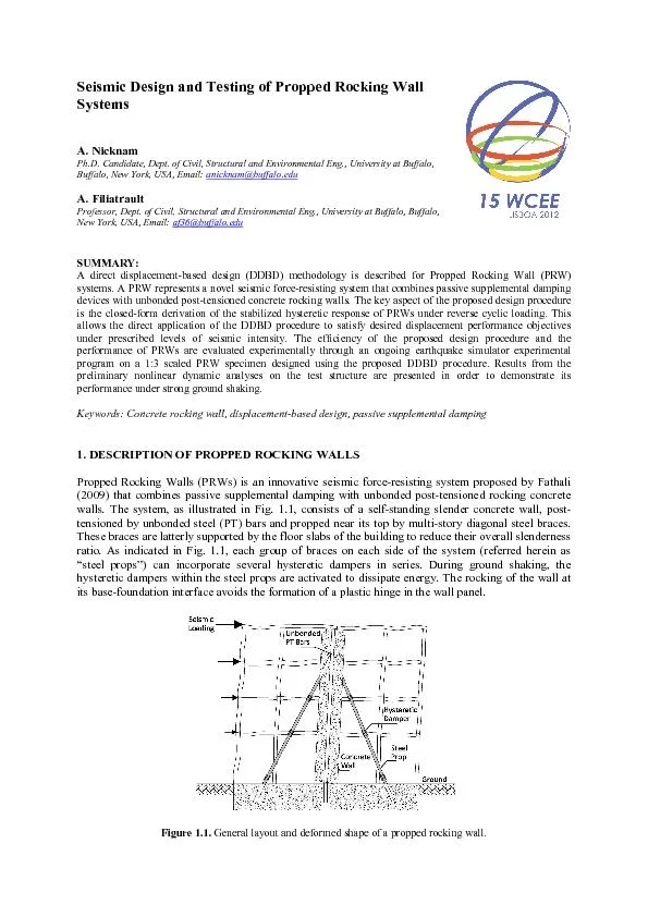
Seismic Design and Testing Systems A NicknamPhD Candidate anicknambuffaloedu A Filiatrault Professor Dept of Civil Structural and Environmental Eng University at Buffalo Buffalo New Y ID: 404988

Seismic Design and Testing Systems A. NicknamPh.D. Candidate

Share:

Link:

Embed:

Download Presentation from below link

Download Pdf The PPT/PDF document "of Propped Rocking Wall" is the property of its rightful owner. Permission is granted to download and print the materials on this web site for personal, non-commercial use only, and to display it on your personal computer provided you do not modify the materials and that you retain all copyright notices contained in the materials. By downloading content from our website, you accept the terms of this agreement.


Presentation Transcript

Seismic Design and Testing of Propped Rocking Wall Systems A. NicknamPh.D. Candidate, anicknam@buffalo.edu A. Filiatrault Professor, Dept. of Civil, Structural and Environmental Eng., University at Buffalo, Buffalo, New York, USA, Email: af36@buffalo.edu Figure 1.1. General layout and deformed shape of a propped rocking wall. Ws represent an extension of the existing Propped Shear Wall (PSWs) system, which has been used in the seismic retrofit of several buildings in the San FranciscoBay Area, CA, U.S.A.(Wolfe et al2001). In PSWs, conventional concrete shear walls are usedand are allowed to hinge at their base for rare and intense ground shaking. The main objectives of this paper are to develop a direct displacementbased design (DDBD) methodology for PRWs and evaluatenumerically and experimentallytheir seismic performance under strong ground shaking. 2. CLOSEDFORM HYSTERETIC RESPONSE OF PROPPED ROCKING WALLSThe behavior of PRWs under cyclic loading depends mostly on the behaviorof two of its main components: 1) the PT bars and 2) the hysteretic dampers.Fig. 2.1(a) and (b) show the freebody diagram of a PRW at maximum response and the base shearroof displacement hysteretic response of the systemunder reverse cyclic loading, respectively. Figure 2(a) The freebody diagram of aPRW at maximum response; and (b) The schematic layout of thestabilized hysteretic response of a PRW system. closedform solution based on smalldisplacements theoryis derivedfor the stabilized hysteretic response of PRWs shown in Fig. 2.1(b). As shown in the figure, the hysteretic response of PRWs is governed by five distinct forcedisplacement coordinates (points and ). Closedformed solutions for eachof these coordinatesbased onthe forcedisplacement coordinates at maximum responseare summarized in Table2.1Table 2.1Summary of the closedform solution for different states of the hysteretic response of PRWs Point Roof Displacement Base Shear A sin )(h2RWLhh4lAEFFemeiPTeW2WPTPTme B m PTPTPT C sin PTPTPT D coshkhFbbWam2a PTPTPT E eerrFF PTPTPTPTPTPT mF Wl Wh eh bh W aF aF clhLAERWWmPTPTPTi2 c 1aF r 2aF mF eF rF m 1a 2a e m Selfcentering of a PRW occurs if the residual force, is positive. This condition can be written in terms of a contribution ratio, as: 1FFFFrere (2.1)In the equations presented in Table 2.1, and are the elastic modulus and gross moment of inertia of the wall, respectively; is the neutral axis depth at the wall base section; is the effective height of the wall defined as the height of the resultant of the first modal lateral forces measured from the wall base; is the weight of the wall; is the initial prestressing force in the PT bars; and are respectively the length and height of the wall; is the activation force of the hysteretic dampers (assumed the same for all dampers); is the horizontal inclination angle of the braces; is the vertical height of the steel props from the wall base; is the axial stiffness of the steel props; and and are the elastic modulus, crosssectional area and unbonded length of the PT bars, respectively.3. DIRECT DISPLACEMENTBASED DESIGN OF PROPPED ROCKING WALLSDirect DisplacementBased Design (DDBD) procedure was developed for PRWs and is described in this section. DDBD was originally proposed by Priestley (1993) and has now been applied to a variety of seismic forceresisting systems. The primary design variables of the DDBD procedure are estimates of the inelastic deformations in the structural elements, which are considered the best indicators of seismic damage. Fig. 1 illustrates the four main steps in the DDBD procedure applied to PRWs. These steps are briefly described below. (1) (2) (3) (4)Figure 3.1. Basic steps of Direct DisplacementBased Design (DDBD) of PRWs.The first step of the DDBD procedure is to develop an equivalent SDOF representation of the PRW under design. This is achieved through the knowledge of the mass distribution and the displacement profile of the PRW at maximum response. The displacement shape (or displacement profile) of the PRW system under design is developed based on a design story drift value set by the designer at the beginningof the design process to insure acceptable levels of deformation for a given level of intensity. In the case of a PRW, the displacement shape at maximum response consists of flexural F F eM eh d eT d y yF uF iK irK eK 05.0 10.0 15.0 20.0 30.0 deformations of the wall under an inverse triangular lateral force distribution representing the effect of inertia forces, flexI, and under the horizontal components of the activation loads in the hysteretic dampers acting in the opposite direction, flexDas well as the rigid body deformation of the wall, rigid , as given in Eqn.1. rigidflexDflexI (3.1)Since the wall is assumed to remain elastic at maximum response under the design level earthquake, each displacement shape included in Eqn.1 can be obtained through the direct integration of its corresponding curvature distribution along the height of the wall. Therefore, flexIflexDand rigid are given by Eqns.2, .3 and .4, respectively. flexI (3.2) flexD (3.3) flexDflexIrigid (3.4)In the above equations, is the total number of stories in the building, is the height of seismic mass from the base of the wall, andis the design drift specified by the designer at the beginning of the design process and assumed constant along the height of the wall.When the displaced shape of the structure at maximum response is known, then the design displacement of the equivalent SDOF system, , at the effective height, , of the SDOF system can be obtained byEqn. 3.5. N1iiiN1i2iidmm (3.5)where are the masses and are the displacements at levegiven by Eqn.1. The effective mass of the SDOF system, , participating in the fundamental mode of vibration at maximum response, as well as the effective height, , are also established using the design displacement profile.As the second step inthe design procedure, the design ductility factor of the equivalent SDOF system, , can be obtained by Eqn. 3.8. The yield displacement at the effective height of the structure, , in this equation is based on an elastic linear displacement profile. dN1iiiemM (3.6) N1iiiN1iiiiemhmh (3.7) eewdydhh (3.8) The third step of the design procedure involves the determination of the equivalent viscous dampingratio at the design displacement. The overall equivalent viscous damping ratio of the system, , at the design displacement is the sum of the inherent elastic damping, , and the hysteretic damping, dissipated during seismic response, as shown in Eqn. 4.9. In this equation, is the postuplift stiffness (slope of branch CD in Fig.), is the inherent damping ratio of the system basedon its initial elastic properties,is the hysteretic damping computed from the hysteretic response of the PRW system at maximum response (see Fig) and is a correction factor to better match nonlinear response (Priestley2007). Based on the closedform solution obtained for the hysteretic response of PRWs, can be expressed as a function of the ductility ratio, , and the contribution ratio, as given in Eqn. 3.9. cheiheeqfrr1 (3.9)As the fourth step of the design procedure, from the design displacement at maximum response, the effective period, , can be obtained from the design displacement response spectrum at the corresponding equivalent damping ratio,, as illustrated in Fig. .1. The effective stiffness, , of the equivalent SDOF system at maximum displacement (see Fig. .1) can then be obtained using the wellknown SDOF expression of Eqn. 3.10. The design base shear force, , is then simply obtained by Eqn. .11 and eventually, the design lateral force at each level of the structure, , is then obtained by Eqn..12. /T (3.10) debKV (3.11) bN1jjjiiiVmmF (3.12)3.1Iterative Numerical Design ProcedureThe iterative DDBD procedure for PRWs starts with a number of predefined material properties and geometric characteristics for the PRW under design, as shown in Table 1. The iterative numerical design procedure for a given PRW aims at achieving the desired designed drift, , for a given design earthquake (DE) displacement response spectrum as well as satisfying simultaneously the following six performance objectives: 1) Full recentering condition: ≥ 1); 2) Eλαstic response of the prestressed reinforcement under the Maximum Considered Earthquake (MCE) defined as a multiplier (e.g. 1.5) of the amplitude of the DE: maxMCE ≤ where ≤ 1.0; 3) Eλαstic response of the concrete wall: wall sections are capacity designed to have a yield moment capacity greater than the amplified maximum bending moment demand at the DE level; 4) Damage control in hysteretic dampers: maximum damper displacement capacity is chosen as twice the MCE displacement demand; 5) Control of neutral axis depth as a ratio of the length of the wall: c/l≤ 0.15; αnd 6) Prevention of wall base sliding by proper design and/or detailing. The wall is considered to extend the full height of the building. An aspect ratio () between 3 and 6 is recommended for the concrete wall. The wall thickness, 'cf3 , is selected to limit the average shear stress in the concrete under the design lateral forces between and 'cf5 per ACI 31811 (ACI2011). The horizontal floor area needed to mount the diagonal steel props is governed by architectural constraints. Based on parametric study conducted by the authorsin one of the first stages of the development of the DDBD procedure, it is recommended that an inclination angle between 60 and 70 degrees be selected for the steel props. Preferably, the steel props should be connected as close as possible to the top of the wall. The six main design parameters for PRWs to be determined from the iterative DDBD procedure include; 1) Initial prestressing force in PT bars, , 2) Activation/Yield force of hysteretic dampers, 3) Axial stiffness of steel props, , 4) Crosssectional area of PT bars, , 5) Neutral axis position, , and 6) Maximum compressive strain in concrete, Table 3.1Predefined structural parameters for DDBD of PRWs. Parameter Description Material Properties f’ f c fy fu fyPT Compressive strength of unconfined concrete Yield strength of nonprestressed reinforcementUltimate strength of nonprestressed reinforcementYield strength of prestressed reinforcementUltimate strength of nonprestressed reinforcement Geometric Characteristics h l W tW W hhb l e Wall total height PT Wall lengthWall thicknessSteel props inclination angleSteel props vertical heightHeight of resultant first mode lateral force Unbonded length of prestressed reinforcement Figure .2. Flow chart for iterative numerical DDBD procedurefor PRWs.The DDBDmethodologydescribed here was embodied in an iterative numerical design procedure on the Matlab platform (Mathworks2011).Fig. .2 shows the flow chart of the design procedure. The DDBD procedure includes two main iterative loops. The loop on the right hand side of the flow chart seeks axial force equilibrium in the PRW. The inner loop on the left hand side of the flow chart seeks moment equilibrium. The final outer loop on the left hand side involves a standard capacity design procedure to avoid premature flexural and shear failures in the concrete wall at maximum response.4. GOING EXPERIMENTAL STUDYAs part of this research,the proposed design procedure and further the performance of PRWs are going to be evaluated through an goingshake table testing programatthe Structural Engineering and Earthquake Simulation Laboratory (SEESL) at University at BuffaloFor this purpose, a 1:3 scalemodel has beendesigned andbuiltand is about to undergo testing at the time of writing. The prototype building selected for this studyis based othe redesigned form of the MCEER West Coast Demonstration Hospital (WC70) Wang, 2007)assumed to be located in Southern California and meeting the requirements ofa Seismic Design Category (SDC) D according to ASCE/SEI 7(ASCE2010).The building s symmetric and has plan dimensions of 108’(32.9 m)by (7.31 m)as illustrated in Fig4.1wo PRW unitsare introduced to provide lateral resistancein the northsouth direction and are located symmetrically on each side of the buildingwith respectto the center of gravityEach propped concrete wall extends the full height of the buildingMoreover, the passive supplemental damping devices used for the props in this case are selected to be in the form of BucklingRestrained Braces (BRBs)(StarSeismic, ). Figure 4.Plan view of the prototype structure(1 ft = 0.305 m)The threedimensional configuration of the test setup is shown in Fig. 4.2The dimensional scale of the specimen is determined based on the limitations of the gravity frame system used to simulate the floor mass of the prototype structure. The Floor Mass Simulator(FMS)is composed of two adjacent frames supporting six steel plates, each weighing about 8.5 kips(37.8 kN)Due to the rocking support design at the baseof its columns, the FMS performs as a pinbased structure in the direction of shaking, resulting in no lateral stiffness in this direction. The braces incorporated in the transversdirection, however, resist deformations in the direction perpendicular the direction of shaking. Figure 4.2. Schematic configuration of the test setup (the PRW specimen installed between two frames of the FMS) on the shake table(1 in. = 2.54 cm)4.1. Design ResultsBased on the similitude relationships, the concrete wall model is of 13’ height with a thickness of in.(20.3 cm) and a length of = 30 in(76.2 cm)The protraction of the props’ axes intersect the Floor Mass Simulator PT Bars Shake Table Extension ame Steel Base Plate Buckling Restrained Braces Load Cell Concrete Wall wall at the third floor (7.27’= 2.21 m). The selfweight of the wall i= 3.25 kips (14.5 kN) and the inclination of the BRBs to the horizontal is = 69The nonprestressed reinforcement is of grade ksi= 413.8 MPa) while theultimate stress of the threaded bars used for the PT reinforcement is 150 ksi(103MPa). Assuming a 7.7 in.(19.6 cm)depth for the location of the PT anchorage underneath the surface of the extension frame on the shake table, the overall unbonded length of the PT reinforcement becomes PT = 13.65(4.16 m). In order to minimize damage in the wall and provide vertical equilibrium against the axial forces due to the PT bars and the selfweight of the wall at the design drift, high strength concrete with a 28day compressive strength ksi (41.4 MPa) is considered. Based on the tributary area between the PRWs, the seismic weight for each PRW is 17.12 kips (76.2 kN) at each floorlevel of the test buildingThe building is assumed to be located on a site with short and 1sec period design spectral values of = 1.g and = 0.6g, respectively, according to ASCE/SEI 710 (ASCE2010).In order to design the building for a seismic performance significantly above codedesign level, a target design story drift of 1= 0.01) under the design level (DE) ground motion was selected. This design drift along with the six performance objectives stated above must be satisfied simultaneously by the DDBD procedure. A contribution ratio = 1 (see Eqn. 2.1) is selected in order to control the selfcentering response of the system while at the same time maximizing the energy dissipation by the BRBs at the design story drift. Table 4.1provides the resulting design properties of the PRWs following the iterative DDBD procedure using the Matlab platform.The effective fundamental period of the PRW was computed as = 0.44sec, and the equivalent damping ratio at the design drift was computed as 12.7% of critical which was composed of 10.3% of hysteretic damping and 2.4% of inherent elastic damping(see Eqn. 3.9Table 4.1Resulting design properties for the threestory PRW test model. No. Parameter Description Unit Design Value 1 23456 R Fi ka Ab c PT c Initial prestressing force in PT reinforcement (per bar) l Activation force of BRBs Axial stiffness of steel props Crosssectional area of PT reinforcement (per bar)Neutral axis positionMaximum compressive strain in concretengitudinal reinforcement ratio kN kN/m 311.8 23.1E+38.17.90.0031.8 . Numerical ModelA numerical model of the PRW structure designed for the shake table testing is developed in PERFORM 3D v4 (Computers and Structures2003). The concrete wall panel is modeled using fiber elements. The smooth stressstrain relationships of the unconfined concrete and the confined concrete are based on the model developed by Mander et al. (1988). A set of eleven nonlinear elastic gapelements introduced at the base of the wall in order to model thegap opening at this section. These contact elements provide zero stiffness in tension and very high stiffness in compressionThe braces are modeled using the BRB inelastic bar type components whichaccount for the isotropic hardening of the buckling restrained braces based on the maximum axial deformation in such elementsThe PT steel bars are modeled using an inelastic steel tie element with inelastic tensiononly steel material. The stressstrainrelationship of the material used for this element is a trilinear idealization of the smooth stressstrain relationship of the PT steel with a strength loss at the point of rupture.4.3. Earthquake Ground MotionsThe earthquake ground motions selectedfor the numerical study were of the 44 historical motions of the FEMA P695 far field ground motion set (FEMA, 2009). The ten ground motions were selected have similar values as the complete P695 motion set for several selected statistical spectral arameters of interest (median, arithmetic mean, geometric mean and standard deviation) within the period range of interest(Sideris et al., 2010)Table 4.2summarizes the characteristics of the similitudescaled reduced earthquake ensemble used in the nonlinear response analyses.According to the P695 ethodology, the ground motions were scaled such that their 5% damped median spectral acceleration at the elastic fundamental period of the PRW (0.sec) matches that of the ASCE/SEI 710 response spectrum for the design spectral values of = 1.g and = 0.6g, respectively. The resulting scaling factor for all ten ground motions wasTable 4Characteristics of reduced P695 ground motion ensemble to be used in experimental study (unscaled). EQ Index EQ IDEarthquakeYearMag.StationFault Type PGA (g) 4 9192021253039 120122 120611 120821 120822 120911 120922 121011 121112 121322 121421 Northridge Imperial ValleyKocaeli, TurkeyKocaeli, TurkeyLandersLandersLoma PrietaManjil, IrCape MendocinoChi, Taiwan 1994 1979 1999 1999 1992 1992 1989 1990 1992 1999 6.7 6.57.57.57.37.36.97.47.07.6 Canyon Country - W Lost Cany DeltaArcelikArcelikYermo Fire StationCoolwaterCapitolaAbbarRio Dell Overpass TCU045 Blind thr ust StrikeslipStrikeslipStrikeslipStrikeslipStrikeslipStrikeslipStrikeslipThrustThrust 1. 35 1.551.011.010.97 4.4. Response History Analyses ResultsTwo dimensional onlinear esponse istory nalyses (NRHA) of the PRW test model were conducted on the PERFORM 3D v4 platform under each of the ten ground motions described above at the DE and MCE intensity levels(defined in this study as1.5 times the amplitude of the DElevel)nherent viscous damping ratioof 2and 5% of critical wereassigned to the fundamentaland highermodeof vibration, respectivelyFigures4.3 and 4.4 illustrate thenumerical predictions of theperformance of the test modelat both DE and MCE levels of intensity. Figure 4.3Peak story drifts, peak residual story drifts and peak absolute floor accelerations for PRW under design (DE) and maximum considered (MCE) earthquake ground motions. MC E MC E MC E D E D E D E Figure PT Elements force usage ratios for PRW under design (DE) and maximum considered (MCE) earthquake ground motions.he effectiveness of the proposed DDBD procedure to achieve the design performance objectivesis confirmed by the result shown in Figs. 4.3 and 4.4. The average peak interstory drift envelopes at both DEand MCE levels(indicated as a solid black lineareless than the target drift(indicated as a dotted red linehe PRW system remains damage free at the DE level, whilethe shear and moment capacitiesfor the wall provide enough safeguards against ollapse at the MCE level.. CONCLUSIONSIn this paper, a Direct DisplacementBased Design (DDBD) procedure is proposed for a novel seismic force resistingsystem incorporating Propped Rocking Wall(PRWs)The effectiveness of the proposed design procedure as well as the performance ofPRWswas conformed numerically. Agoing shake table testing programis now aimed at verifying experimentally the seismic performance of PRWs. AKCNOWLEDGEMENTThe authors would like also to thank David Mar, S.E., from Tipping Mar & Associates, Berkeley, CA, U.S.A., for his collaboration in the initial phases of this research work and StarSeismic, LLC for donating thebucklingrestrained braces to be used in the exprimental studyREFERENCES American Concrete Institute (2011), ACI 31811: Building Code Requirements for Structural Concrete and CommentaryFarmington Hills, MIAmerican Society of Civil Engineers2010ASCE Standard ASCE/SEI 710: Minimum Design Loads for Buildings and other Structureseston, VFathali, S.Personal ommunications. Mander, J. B., Priestley, M. J. N. and Park, R. (1988). Observed StressStrain Behavior of Confined ConcreteJournal of Structural Engineering114, 18271849.Priestley, M. J. N. (1993). Myths and Fallacies in Earthquake Engineering Conflicts between Design and Reality. Bulletin of NZ National Society for Earthquake Engineering. New Zealand, , 329341. iestley, M. J. N., Calvi, G. M.and Kowalsky, M. J. (2007. Displacement Based Seismic Design of StructuresIUSS Press, Pavia, Italy.Sideris, P., Filiatrault, A., Leclerc, M. and Tremblay, R. (2010). Experimental Investigation on the Seismic Behavior of Palletized Merchandise in Steel Storage Racks. Earthquake Spectra., 209233.StarSeismic, LLC. (2012). Park City, UT, U.S.A. Web: www.starseismic.netWang, D. (2007). Numerical and Experimental Studies of SelfCentering PostTensioned Steel Frames. Ph.D. Dissertation. State University of New York at Buffalo, Buffalo, NY, U.S.A. Wolfe, J., Mar, D. and Tipping, S.2001. Propped Shear WallsCombining Steel Braces And Concrete Shear Wallsfor Seismic StrengtheningExisting BuildingsModern Steel Constructionuary, 5 p. D E MC E