/
1Pro/SHEETMETAL 1Pro/SHEETMETAL

1Pro/SHEETMETAL - PDF document

tatyana-admore
tatyana-admore . @tatyana-admore
Follow
375 views
Uploaded On 2016-08-17

1Pro/SHEETMETAL - PPT Presentation

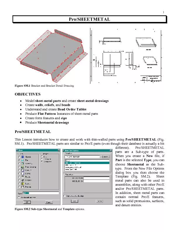
sheet metal drawingswalls Instances of sheet metal parts Create form features and x2022 Produce Sheetmetal drawings This Lesson introduces how to create and work with thinwalled parts using SM1 ID: 450491

sheet metal drawingswalls Instances

Share:

Link:

Embed:

Download Presentation from below link

Download Pdf The PPT/PDF document "1Pro/SHEETMETAL" is the property of its rightful owner. Permission is granted to download and print the materials on this web site for personal, non-commercial use only, and to display it on your personal computer provided you do not modify the materials and that you retain all copyright notices contained in the materials. By downloading content from our website, you accept the terms of this agreement.


Presentation Transcript

1Pro/SHEETMETAL sheet metal drawingswalls Instances of sheet metal parts Create form features and • Produce Sheetmetal drawings This Lesson introduces how to create and work with thin-walled parts using SM.1). Pro/SHEETMETAL parts are similar to Pro/E parts (even though their database is actually a bit different). Pro/SHEETMETAL parts are a Sub-type of parts. When you create a file, if is the selected as the Sub-type. From the New File Options dialog box you then choose the Template (Fig. SM.2). Sheet metal parts can also be used in assemblies, along with other Pro/E and/or Pro/SHEETMETAL parts. In addition, sheet metal parts can contain normal Pro/E features, such as solid protrusions, surfaces, and datum entities. options. Using Pro/SHEETMETAL, you can create parts in either their formed (bent) shape (Fig. SM.3) or the flattened shape. Once created, these parts can then be formed or flattened, as required. You can also to maintain the part in both states. If you have COAch for Pro/E on your system, go to Sheet Metal Design and complete the lessons. As sheet metal parts are flattened (or formed if you start with a flat state), Pro/SHEETMETAL utilizes a "" to allow for the fact that metal is elastic and stretches as it bends. Pro/SHEETMETAL will subtract from the actual length of the material to compensate for the elasticity. You can substitute a for the factor if you so desire. Several default bend tables are d on the tables from the Machinery Handbook. The Pro/E part database is different when you create parts using Pro/SHEETMETAL. All sheet metal parts are by definition thin-walled constant-thickness parts. Because of this, sheet metal parts have some unique properties, that other Pro/E parts do no have. You may convert a solid part into a sheet metal part, but not a sheet metal part into a solid part. The solid must be a constant thickness. All sheet metal parts are constructed of features known as A sheet metal feature is analogous to a Solid Protrusion. When you create Wall features, Pro/E is actually doing a great deal of work behind the scenes--internal datum planes and automatic alignment points that never appear on the Another important sheet metal feature is a . Bends are often generated automatically during the creation of Wall features. Sheet metal drawings usually contain views both of the fully formed part and of flat pattern, as in Figure SM.4. You can place views of the part in both states on the same drawing by creating a multi-model drawing. There are many similarities between creating solid features in Pro/E and in Pro/SHEETMETAL. However, Pro/SHEETMETAL offers some additional special features. To create a sheet metal part in Pro/E, choose instead of selecting from the (file) dialog. The FEAT CLASS menu structure appears differently in Pro/SHEETMETAL mode. The first feature in any sheet metal part must always be a feature, which is analogous to a protrusion. After constructing the first Wall feature, you may create surface or solid features, as well as datum or sheet metal features. The OPTIONS menu is used only when constructing the first feature. Subsequent sheet metal features are created from a different menu. Most of these options should look familiar; their functionality There are two new options available when creating the first feature in Sheet metal mode: . The option creates a wall that is offset from an existing surface. This is most useful for creating feature geometry in Assembly mode. With the option, you can sketch the outline of a Sketch of First Wall and Modeled Wall In general, it is most effective to create sheet metal designs in their bent state and then unbend them for flat pattern geometry. Create your design as per your design intent. It is not necessary to create the design in the order of manufacture. Sheet metal parts can be created in the Part mode or the Assembly mode. You can use the top-down approach to design when you use the Assembly mode. Typical sheet metal structures that can be designed with nd supporting structures for electrical and mechanical equipment (Fig. SM.6). In these structures around the internal components. As with regular Pro/E parts created in Assembly mode, a sheet metal part can be dimensioned to the component parts that it is supporting. Before starting to create sheet metal features, remember to design the part in the condition, i.e., not as a flat pattern, unless you know all flat pattern details and dimensions. (Problems can arise when you modify a part that was designed as a flat pattern). Add as many bends to the part as possible before adding other features. Creating cuts at an angle or through bend areas might require larger dimensions for proper clearance. The proper feature creation order (Fig. SM.7) Order of Feature Creation andIf you choose to create a sheet metal part in Sheet Metal mode, the first feature (other than datums) must be a wall. There are two types of walls: and Pro/E all the other feature types in the SHEET METAL menu until you have created the first (base) wall. There are several options for The feature forms available for the base wall include: Base Feature, Extruded Wall Base Feature, Revolved Base Create a sheet metal wall by blending several sections sketched in parallel planes as shown Figure SM.10 Base Feature, Blended Wall Figure SM.11 Feature, Flat Wall Create a wall that is offset from a surface (Fig. SM.12). Figure SM.12 Base Feature, Offset Wall Create a sheet metal wall-using datum curves, multiple trajectories. Because you are in Sheet Metal mode, any features that you created through this menu are thin ones. Viewing a Sheet Metal PartWhen manipulating models (like sheet metal or die-cast parts) it is often difficult to select the thin side surfaces when you wish to orient the view. Because of the thinness of a sheet metal part, using edges for orienting the part is more convenient than using the side surfaces. To orient the part: Choose a view command (, for example); then select a surface (wall). Select the corresponding view command (, for example) and select an edge of a wall. You can add flat walls, extruded walls, swept walls, extends, twists, and merged walls. They are attached to the edges on the part. Except for the Extends, these waportion of it (partial walls, Sweeps, and Twists). Extends extrude a wall along the full length of the specified edge. You can also add unattached walls, independent of the base wall, by checking in the Wall menu. The choice of walls to add to the base wall will depend on your design intent. Flat Walls and extruded walls must be attached to planar surfaces. Their attachment edges must be straight lines. Flat walls can have a section of any shape, but their profile is always flat. walls can be sketched with a more complex profile. Extruded walls are always created as rectangular because they are extruded to a uniform depth; however, you can afterwards add features to modify the wall shape. Swept walls can be attached to virtually any surface. Their attachment edge need only be a tangent The three major geometry types for additional walls are and Swept walls are a subset of walls). With two additional menu options, No Radius and Flat WallNo Radius Sketch the boundaries of the wall attached to the selected edge. The adjacent wall must be either planar or a twist. The attachment edge must be a straight line. The new wall is automatically created coplanar with the adjacent planar wall or tangential with the end Flat Wall-No Radius or No Radius Sketch the side section of the wall that will be extruded along the attachment edge. You determine whether a bend is to be created when you are sketching the section. For a partial wall, the adjacent wall must be planar. For an extruded wall, the adjacent wall must be either planar or a twist. In all cases, the attachment edge must be a straight Extruded or Partial Wall-No RadiusSwept Wall,No Radius Use this to attach a wall to almost any type of surface. The sweep trajectory is the attachment edge of the adjacent wall. It must be a tangent chain but it can be three-dimensional. Sketch the side section of the wall. Determine whether a bend is to be created Flat Wall, Sketch the boundaries of the wall attached to the selected edge. The sketching plane is set up at a specified angle, and the radius is added after you create the wall. Note that material is removed from the wall-wall intersection (as shown in Figure SM.15, ). If the wall is not attached to the edge vertices, you have to use reliefs to create the wall geometry properly. The adjacent wall must be planar, and the attachment edge must be a straight line. Flat Wall, Use Radius or wall, Sketch the side section of the wall that will be extruded along the attachment edge. The bend radius for the wall is added after you create the wall. Note that material is removed from the wall at the bend location. For a wall (Fig. SM.16), you have to use reliefs to create the wall geometry properly. The adjacent wall must be planar, and the attachment edge must be a straight line. Extruded or Partial Wall, Use Radius Swept Wall Use this to attach a wall to almost any type of surface. The sweep trajectory is the attachment edge of the adjacent wall. It must be a tangent chain, but it can be three-dimensional. Sketch the side section of the wall. The limitation is that the line of intersection between the sketching plane and the adjacent surface must be a straight line. Twist Use this wall to change the plane of a part. Its adjacent wall must be planar, and the attachment edge must be a straight line (Fig. SM.17). 8 Twist Wall Merge After you have sketched the new wall and the sketch has been regenerated, the Relief menu appears with the following choices: w/Relief Brings up the RELIEF TYPE menu. Pro/E highlights each attachment point in turn and prompts you to select the kind of relief option: You are prompted to enter the In Figure SM.19(A), a flat wall is attached at an angle to an existing flat wall. The new wall does not run the full length of the attachment. Therefore, if it is to be attached at an angle, it must have relief. If it 9is to be attached without relief, then it cannot be at an angle. In that case, you can add a bend later. Figure SM.19 (A) Rip and Stretch Reliefs Figure SM.19 (B) Figure SM.19 (C) Creating a Flat Wall Menus Used to Create Flat, Extruded, Partial, and Swept WallsWhen you create a flat, extruded, or partial wall, you must specify a bend table. If you use the option when creating a flat, extruded, partial, or swept wall, you must also specify the relief and radius. Dialog boxes are used to define these types of walls. In the main dialog box for each of these types of walls, you define the bend table, relief, and radius elements. When you select one of these elements, the appropriate menu appears to aid in your definition. Use the USE TABLE menu to specify the type of bend table to assign to the bend: If you select the option to create a flat, extruded, partial, or swept wall, use the RELIEF menu to specify the following: w/Relief Create the wall with relief. The RELIEF TYPE menu appears with the following Create wall with stretch relief. Create wall with rip relief. • ObrndRlief Create wall with obrnd relief.If you select the option to create a flat, extruded, partial, or swept wall, use the SELECT RADIUS menu to specify the following: Thickness Sheet metal thickness. From Table If a has been assigned and you select this option, the FROM TABLE menu A flat wall (Fig. SM.20) is attached to a selected edge, and you sketch the boundaries of the wall in a plane at the bend angle of the finished wall. The surface adjacent to the edge must be planar. When you create a flat wall, you must sketch the Flat Wall as an and attach the Flat Wall to either the green or the white side of the Attach Edge, with its attachment points inside (or aligned with) If the Flat Wall has a radius and rip relief, and you dimension it to the inner surfaces of adjacent walls then; you can set the offset distance to zero. Pro/E relieves the Flat Wall as shown in Figure SM.20(d). This is functionally equivalent to the effect that you would get if you created the Flat Wall with real offset dimensions, as in Figure SM.20( Creating a Flat Wall is attached to an edge and always extrudes the complete length of the edge. The surface adjacent to the edge must be planar (Fig. SM.21). Extruded Partial Wall, with the option No Radius If an extruded wall section is to be tangent to the adjacent surface (Fig. SM.22), you have to make sure your entity at the attachment point is tangent. Creating Tangent Walls Thicken command to dimension to both sheet metal surfaces while creating an extruded wall (Fig. SM.23). This enables you to dimension the inside bend radii on opposite sides of the section, or to create dimensions needed for proper sizing or clearance, and so on. This way, you do not have to add material thickness to your dimension values. Thickening a Wall Section There are two ways to create partial walls in sheet metal parts: One way is to sketch a Flat wall not connected to the endpoints of the attachment edge (Fig. SM.24). Or, you can use the create a partial wall by sketching its profile. This wall starts from a datum point (which you specify) and runs for a specific depth (which you also specify). Partial walls can be created on an edge where they Flat Partial Wall with Rip Reliefs A Partial Wall Crossing a BendYou must use reliefs when you create any type of partial wall with Using Reliefs for Partial Walls Partial ExtrudedWall with (Fig. SM.28) feature enables you to model various overlap conditions, mainly at corners. An feature extends out from a straight edge of an existing planar surface. It can either extend for a specified length or extend up to a specified plane (may be either a datum plane or Sheet Metal Corner, with Various Degrees of Overlap Twists Twist is a special wall that can be used to change the plane of a sheet metal part. Twists serve as transitions between two areas of sheet metal, and the twist angle is relatively small (Fig. SM.29). It is attached to a straight edge (the attach edge) on an existing plane wall (Fig. SM.30). It can be rectangular or trapezoidal. It has an axis (the twist axis) running through its center, perpendicular to the When creating a twist wall, you can add a flat or an extruded wall at the end of a twist only if the wall was created with no radius and tangent to the twist. You can unbend a twist using the Regular menu options. Flat Wall with Attached Twist feature can be used to create a or cut or to create the UDFs used for notches and punches. The techniques used to create a cut in Sheet Metal mode are similar to those used in Part mode. Sheet metal cuts are always made on the green or white surfaces and never on the edges.The white surface is offset from the green surface by the sheet thickness. Sheet metal cuts are sketched on a plane and then projected onto the sheet metal. The cuts are made normal to the sheet metal surface and can be driven from either the green side or the white side. If you want the feature to cut the material at a defined angle, then you should use a Some (e.g. holes, rounds, chamfers, slots, cuts) are available for use in sheet metal parts. They can be added in Sheet Metal mode. Solid-class features can be plWhen you make a Sheet Metal-Class cut, you must select whether the cut is going to be or If you choose , then you must sketch the cut with all its dimensions. If you choose then you need sketch only a simple line sketch for a cut that will have uniform thickness (width). Figure SM.31 shows a Sheet Metal-Class cut in a curved sheet metal part. The cut was defined first as a solid Sheet Metal CutsIn general, a rip is a zero-volume cut that is created on a sheet metal part. If your part is designed as a continuous piece of material, it cannot be unbent without ripping the sheet. Create a feature before unbending. You can choose among a number of different rips, including: Select the surface on which to create the rip and then sketch the rip section. Pro/E Select a surface and rip the geometry out. This option effectively cuts out the selected surface and so actually removes volume. (Fig. SM.33). Regular Rip Figure SM.33 Surface Rip and Unbend Edge Rip and Unbend When you unbend a part with a the material breaks along the rip section (Fig. SM.35). Regular Rip and Unbend This section describes the bend, unbend, and bend back features. You can also make a projected datum curve follow the unbending and bending back of sheet metal surfaces. consists of Regular unbends, Transition unbends, Cross-section- enables you to return a bend that has been unbent, to its original condition. Proper use of unbends and bend back features is very important for sheet metal design. Adding a bend back feature is not the same as deleting an unbend. The suggested practice as follows: If you add an unbend (or bend back) feature just to see how the part looks in a flattened (unbent) condition, delete it before proceeding. Do not add unnecessary pairs of unbend/bend back features; they inflate the part size and might cause problems at regeneration. If you specifically want to create some features in a flattened state, add an feature, create the features you want, and then add a feature. Do not delete the feature in this case; features that reference it might fail regeneration. Not only are bends added to the part when a wall feature is created, but the sheet metal part can have bends added at any time via the command. The part can be bent and unbent around these bends again and again by means of the feature is used to add a bend to a flat section of the part. You cannot add a bend where it crosses another bend, but bends can be added across form features. Examples of BendsWhen adding bends, consider the following: You cannot copy a Bend feature by mirroring it. You can generally unbend zero-radius bends; however, you cannot unbend those that have slanted cuts across them. For all regular bends, you must specify the relief to be used. After you have sketched the bend and the sketch has been regenerated, the RELIEF menu appears. In Figure SM.37, a simple to be bent on a line that is a short distance above the imaginary line where the upper left part meets the main lower part. In the three relief examples, the large lower area was selected as the fixed area for the Figure SM.38 Bend with No ReliefThe results can be summarized as follows: Bend with No Relief The upper part of the fixed area was also bent, along its full width (Fig. Bend with Rip Relief The material in the fixed section was cut normal to the bend line, to provide Bend with Stretch Relief The material in the corner between the fixed and bent sections was stretched to provide the bend relief. Note, in the unbent view, the relief width and relief angle Figure SM.39 Bend with Rip Relief Bend with Stretch Relief Bends can be a combination of attributes--one from each of the following groups: Create a bend with a specified radius. The resulting angle is determined by both the radius and the amount of flat material to be bent; (default) Create a normal bend with no transition surfaces w/Transition Deform the surface between the bend and an area you want to remain flat Part Bend Table (default) Use the bend table assigned to the part to calculate the developed w/ Relief Create automatic bend reliefs. Regular Angle Bend bend (Fig. SM.42) is sketched like that for an angle bend; the direction of bending, however, is determined when you select the direction of viewing the sketching plane. The bend is created in the direction you are viewing--that is, away from you. Roll Bend You can create bend order tables and display them in sheet metal drawings to document the order and dimensions of bend features. Bend order tables can be updated by reviewing the bend sequence. When a bend order table is stored, the file name is . A bend order table cannot be created or edited on a completely unfolded model. This bend order table shown in Figure SM.43 is based on the completed part that is shown in Figure SM.44. The bend sequences for the part are shown in Figure Bend Order Table Bend Sequences Completed Sheet Metal Part To write the bend order table to a file and display it on the screen, choose from the BEND ORDER menu. In the bend order table, a bend's direction is considered to be in when it is less than acute or obtuse) on the side. It is considered to be out when it is greater than (i.e., oblique) on feature to unbend any curved surface on the sheet metal part, whether it is a bend feature or a curved wall. Use the UNBEND OPT menu to do the following: • Regular (default) Pick an existing bend or wall feature to unbend. You can use this option to unbend most bends in a part. After the bend, the surfaces that were tangential to the bend are in the same plane. If you select all bends, you create a flat pattern of your part. Select stationary surfaces and transitional surfaces to create an unbend feature. This Select stationary surfaces and specify a cross-sectional curve to determine the shape of the unbend feature. This can be used on undevelopable surfaces, such as hems and flanges. Most bends in a part can be unbent with the regular option as shown in Figure SM.46 and Figure SM.47. Use the regular option to unbend undevelopable (deformed) surfaces and twists. The dialog box to unbend a regular bend appears when you select from the UNBEND OPTS menu. The dialog box lists the following elements: (required) The region of the model that is to remain fixed during the unbend. Bend Sequences Figure SM.47 Unbent Bend When a bend has been unbent, you can use the command to return it to its original condition. a deform area, you might not be able to complete the bend back to the fully formed condition. As a rule, you should bend back only a fully unbent area. When creating a feature, you can specify contours to remain unbent (Fig. SM.48). The dialog box for a regular roll bend appears when you select from the OPTIONS menu. The dialog box lists the following elements: (required) The region of the model that is to remain fixed during the bend back. Geom (required) The unbent feature to be bent back. Use the BENDBACKSEL menu after you select the Geom element to do the The GET SELECT menu appears. Select one or more Unbends to bend All Unbends are bent back automatically. As Pro/E bends back each selected unbend, it examines its contours. If it finds that a contour partially intersects the bend area, it highlights that part of the contour and prompts you as to whether you want this contour to remain flat (Fig. SM.49). Bend Backs with Contours Intersecting Bend Areas Flat Pattern is equivalent to an feature, but it is always positioned last in the part feature sequence. You can create a Flat Pattern feature early in the design, to get started on drawings and manufacturing. If new features are later added to the part, they are automatically reordered before the After you create the Flat Pattern, the part always displays in the flattened state; however, once you start creating a new feature, the Flat Pattern is temporarily suppressed, and then it is automatically resumed and reordered when the new feature is completed. If you do not want the part to be constantly rn feature and resume it only when you want to see In order to simplify and streamline the creation of Flat Pattern representations for manufacturing, a FLAT STATE menu (called FLAT STAT) is provided. It is accessed through the SHEET METAL SETUP menu (see left column). It can be used to create instances directly, without having to edit the part's family table. The instances thus created are initially completely unbent (Fig. SM.55). instances behave like those created in regular family table members. Fully Formed Part aIf you subsequently choose the option from the FLAT STAT menu, then all the features that were added/enabled in any and all of the Flat State instances are enabled (resumed) in the generic and in all the instances, except in those instances in which they were specifically suppressed. The system enables you to clean up the family table by removing from it all the features that are now enabled in the You can create the first flat state instance from a generic that is either fully formed or fully flat. If the generic is (fully) formed, then the system brings up the Unbend feature editor and prompts you for the Unbends necessary to make it fully flat. After you choose , the system creates the instance. You can display and dimension a on the same drawing with the detailed sheet metal part and its dimensioned views.If the generic is in the active window, choose from the FAMILY TABLE menu, and then choose the particular instance from the Instances namelist menu. If the generic is in the active window, choose from the FLAT STAT menu; then choose the particular instance from the FLAT MODELS NAMELIST menu. • If you are retrieving the part through the ENTERPART menu, you have the choice of retrieving You have already created a wide variety of parts, assemblies, and drawings using this text. By now you should be so proficient using Pro/E that a step-by-step cookbook recipe of a sheet metal part should not be unnecessary. Therefore, in this version of the text this new lesson introducing Pro/SHEETMETAL will utilize a different format. We will introduce a wide range of part design concepts, commands, and capabilities as they apply to sheet metal (Fig. SM.52). At the end of the material by creating a sheet metal part and documentiof the lesson will require that you create a number of very simple parts that will be used to demonstrate Here is one possible design approach to follow for creating sheet metal parts: 1. Create the basic sheet metal parts in Sheet Metal mode. Because many of the components will be held in place with screws or bent tabs, you might want to leave the creation of these features for later when the components are assembled. 2. Create the assembly by assembling all major internal components relative to each other(Fig. SM.53). Include simple supporting structures, or sheet metal parts that are not completely defined at this time, to place the components. 3. Create or modify the sheet metal parts using the internal components as references. This aids you in adding supporting walls, form features for stiffening panels, and punches and notches for fastening the components. 4. After the cabinet and supporting structures are defined relative to the internal components and each other, add any remaining components, sheet metal, or assembly features. 5. Create and/or select a bend table to provide material allowances when unbending the part. This could also be done as the first step in the design. Flat State instance. This creates your flat pattern for drawing and manufacturing. The bend table data ensures that the flat pattern’s geometry is accurate. 8. Document the parts by creating drawings; you can include both the generic (as designed) part and the Flat State instance (multi-model drawing). Show the dimensions for the as-designed part, and show/create dimensions for the flat pattern part. Add the bend order table as a note. Components and Sheet Metal Platform, Before Assembly Components and Sheet Metal Enclosure, After Assembly A sheet metal part can be created in Sheet Metal mode or in Assembly mode as a sheet metal component, or it can be a regular part that has a constant thickness that is converted to a sheet metal part. (You cannot merge sheet metal parts with other assembly components.) A sheet metal part appears with green and white surfaces, with side surfaces in between. surface is the driving surface. This helps in visualizing the part and geometry selection, because sheet metal parts are comparatively thin. Sheet metal parts have a constant thickness; Pro/E creates the white surface by offsetting the material thickness from the green. The side surfaces are not added until the part Pro/SHEETMETAL uses a set of features unique to sheet metal parts. Sheet metal features can be added to a sheet metal part when the part is completely unbent, when it is completely bent in its design condition, or at any stage of bend/unbend in-between. Sheet metal parts cannot be retrieved in Part mode. In Sheet Metal mode, you can create datum, cosmetic, and some Solid-class features, such as holes, slots, chamfers, and (flat) protrusions. You can set up certain parameters and conditions prior to adding features to your sheet metal part, the method to calculate the developed length of flat sheet metal required to make a a table to document the order and dimensions of bend sequences. the default surface or edge that remains fixed when you bend or bend back the part. Bend AllowanceBend allowance is a method to calculate the length of flat sheet metal required to make a bend of a used to calculate the bend allowance. When Pro/E looks for a value and does not find it in the bend table data, it uses the formula equation. Use one of the following three methods to calculate the bend allowance: The system default equation Pro/SHEETMETAL allows you to specify a for a Sheet Metal part. You may also define a different Bend Table for each feature, if required. You can specify which Bend Table you want to use feature (as you may have noticed). The default Bend Tables that are supplied with Pro/SHEETMETAL is copied from (and used with the permission of) the The tables are based on the hardness and of the material being used: Table Name Material Y-Factor K-Factor TABLE1 Soft Brass and TABLE2 Hard Brass and Aluminum TABLE3 Hard Copper Bend Tables apply only to constant-radius bends. The flat pattern size of variable-radius bends is determined by the Y-factor formula. If you have some other method of developing Flat Pattern lengths of bends, you must create user-defined Bend Tables.When you create any sheet metal Bend feature, you can specify that it reference either the Part Bend Most of the time, you should select Part Bend Table, since the behavior of bends is usually the same for all Bend features in the part. Possible exceptions to this rule are multiple-material models or when you have user-defined Bend Tables that take the grain of the material into account. In this case, you may have one table for across-grain features, and another table for along-Note that the default Bend Tables supplied with Pro/SHEETMETAL do not account for the material grain direction. The Part Bend Table is specified with the option. Each bend can be made to reference it by selecting the Part Bend Tbloption. If you choose the Feat Bend Tbloption, Pro/E displays menus that allow you to select from the tables located in the Bend ⇒ TABLE2). You can make a particular or feature reference a different bend table from the bend table associated with the overall part. At the time of creating a or feature, you have Part Bend Tbl The bend table associated with the part is used for developed length calculations. If no table is currently assigned to the part, the Y-factor formula is used. Feat Bend Tbl Specify a separate bend table to be used by the feature. Select one of the three supplied bend tables from the Data Files namelist menu, or choose and enter the name of Sheetmetal icons and context sensitive text Create Conversion Create Flat Wall Use Radius Create Flat Wall No Radius Create Extruded Wall Use Radius Create Extruded Wall No Radius Create Swept Wall Use Radius Create Swept Wall No Radius Create Unattached Flat Wall Create Unattached Extruded Wall Create Revolved Wall Create Blended Wall Create Offset Wall Create SMT-Class Cut Solid Create Extended Wall Create Wall Create Bend Create Hem Create Bended Edge Create Unbend Create Bend Back Create Corner Relief Create Punch Create Notch Create Rip Merge Walls Create Form Create Flatten Form Create Deform Area Create Flat Pattern Lesson SM STEPS The first part is a simple sheet metal part using the Flat Wall Sheet Metal Part (SM_FLAT_1⇒ New Part (type the part name Use default (fill in the parameters) New File Options Dialogs Uncheck Add your parameters Establish your material and working environment: (Define material) Edit ⇒ Setup Material (table of material properties, change, keep, or add information) Save File Exit Assign Accept (Set environment) Tools Environment Spin Center Snap to Grid Hidden Line, Tangent Edges Dimmed OK sheet metal-class feature will be a wall feature: Create Unattached Flat Wall as the plane) MMB MMB (to accept default MMB and as the Create Lines (sketch, and modify as in Fig. SM.56) Preview Sketch for Flat Wall Completed Flat Wall Part Window Close Window The next first wall will be created with the option. This is very similar to creating a feature with the option. Use the same setup and environment as with the first part, with the exception of using metric units (mm). ⇒ New Part (type the part name Use (fill in the Parameters) The sketch will create a simple feature that conforms to prompt for the " Create Unattached Extruded Wall Both Sides MMB as the MMB MMB MMB (sketch, dimension, and modify as in Fig. SM.58) appears, indicating the side of the section on which the material thickness will be added. Make sure the arrow points toward the of the section.) (if MMB (enter thickness MMB Blind MMB Preview Sketch for Extruded Wall Thicken Direction for Extruded Wall Extrude Direction Extruded First WallObserve the relationship between the sketch and the feature. Currently, the surface is on the Click on the wall feature ⇒ RMB this is because the "thicken" direction was to the inside (Fig. SM.62). The sketch creates the (driving) surface and offsets the (driven) surface from it. Redefine Click on the wall feature with RMB Redefine MaterialSide Define Flip [so the arrow is pointed outward (Fig. SM.63)] MMB OK (Fig. SM.64)] Flip the Material Side So That the Material Is Added to the Outside (as well as the Green Driving Side)The feature is redefined. Now the surface is on the inside, and the surface is on the outside. Measure the distance between on the inside and the wall was created with the material side pointing outward (Fig. SM.65 (A)). Figure SM.65 (A)Side is on the Inside (Redefined design) Figure SM.65 (B) The Sketch, as well as the Green Driving Side is on the Outside (Original-Saved design) ⇒ Erase ⇒ Current ⇒ Yes To convert a part that was created in "solid" mode into a sheet metal part, you simply retrieve it in sheet metal mode. As a part of the conversion process, Pro/E turns the part geometry into a constant-thickness configuration, based on your input. There are two options available in Pro/SHEETMETAL to accomplish and . The option behaves exactly as it does in solid mode--the outside of the geometry is offset inwards, and the part becomes hollowed out. The outside of the part becomes the surface. The only works for a Thin Protrusion. This option recognizes that the part is Create the solid Pro/E part not a sheet metal part (Fig. SM.66 and SM.67). the part from memory. Figure SM.66 Solid Pro/E Part Section option convert the existing solid part just created into a sheet metal part: MMB Applications (from the Menu Bar) [select the three surfaces to remove (Fig. SM.68)] MMB MMB .125 MMB (Fig. SM.69) MMB File Erase Current Yes The part is shelled and converted to a sheet metal part. The Pick the two ends and the bottom surface as shown. Converted Part You can also convert a thin-walled solid into a sheet metal part by defining a driving surface. Pro/E then converts the database of the part and saves the driving-surface and driven-surface information. You must begin with a constant-wall-thickness part to use this option. The most common example of a solid with a constant thickness is one that was created with the protrusion or a solid which contains a feature. When you choose a face that lies on one "side" of the constant-thickness wall, Pro/E selects all adjacent faces and converts these surfaces to the driving surface. The surfaces that lie on the other side of the constant thickness from the driving surfaces become the driven surface. Obviously, there are some limitations to this technique. The part must truly be of a constant thickness and there must not be features protruding from the driving or the driven surface. option allows you to create a feature by extruding a cross section sketch along a linear edge of a sheet metal part. The edge along whas the Attach Edge. The sketch should be constructed as if it were for a Thin Solid feature (in Part Mode)--the cross section is automatically thThere is a variety of information that must be defined in order to create an feature (Fig. SM.70). The first item necessary for any is the Attach Edge. This may be any linear edge of the part. Next, you must choose either the or the No Radius option for the . Choosing the Use Radius option causes Pro/ENGINEER to place a into the Wall feature automatically. The option is used for specialized circumstances. Extruded Walls Options If you choose the option, you must then define several attributes that relate to the geometry. The Radius Type setting controls whether you want to specify the or the bend radius (Fig. SM.70). This setting will depend upon the particular design and manufacturing constraints for the Wall feature. The Radius Value setting may be set to , which allows you to enter a Radius Value, or to Material Thickness, which automatically sets the radius value equal to the part's material thickness parameter. The final two pieces of information necessary for every Extruded Wall and the specification. Bend Tables are used to define material deformation when creating Bend features. Bend Relief must be defined whenever a Wall feature cannot be added to the part without deforming or ripping the existing material. Much of the required information for sheet metal features can be preset using ⇒ Parameters and completing the cell information Sheetmetal Parameters feature on both sides of the part: ⇒ Pick SM_FLAT_1 MMB Create Extruded Wall Use Radius Part Bend Tbl MMB Inside Rad MMB One Side MMB select the Attach Edge side) (Fig. SM.72) select thesketching plane (the edge surface as shown) MMB to accept default viewing direction Bottom select the plane surface as shown (Fig. SM.74) Close (References) Figure SM.72 Attach Edge Figure SM.73 Viewing Direction ) Orientation Plane Notice the sketch alignment "magnet" point () (Fig. SM.75). Any sketch entities, which are located near to this point, will be automatically aligned to it. Youdo not have to align the entities manually. Magnet Point Create and modify the one line sketch (Fig. SM.76) No Relief MMB Thickness Preview Figure SM.76 Sketch Extruded Wall, Completed Feature Create another wall on the opposite of the part (Fig. SM.78): Create Extruded Wall Use Radius complete the wall using side again), a wall length of and a radius value of (Fig. SM.79). Extended Wall on Opposite Side of Part Extended Wall on Opposite Side of Part Angled wall features can be created using the Extruded option by sketching the cross section with an angular dimension. It is good design practice to create even features with an angle dimension unless you are certain that they will always remain perpendicular. By following this practice, you will build additional flexibility into your models, because you can then easily modify the angle dimension to whatever value is necessary. To create a right-angle bend, with the flexibility to be changed to another angle, you sketch the line that represents the wall at an angle that is clearly not If you sketch it near the system will assume that it is so and assign a constraint that you would need to disable. Add an angle dimension and then change the angle dimension value to thus allowing it to be easily modified. Create an angled wall: Create Extruded Wall Use Radius Complete the featurebut draw the wall line at an angle. Inside Rad, with dimensions of long and at an angle of ° (Fig. SM.80). Use .50 for the radius. Figure SM.80 (A) Attach Edge (B) Sketch Plane (C) View Direction (D) Orientation Plane (E) Magnet point (F) Sketch the angled wall (G) Complete the sketch (H) Preview (I) Angled Wall Modify the angle to 135 (Fig. SM.81). Modified Angled Wall When creating features, it is important to select the correct Attach Edge in order to preserve the design intent of the part. The edge that is selected as the Attach Edge for an Extruded Wall controls the feature's dimensioning scheme. As you may guess, selecting the proper Attach Edge for a Wall feature will help you to maintain the design intent for the part. Try redefining some of the Extruded Walls you have created. Select different Attach Edges and see how the part and its dimensions change Figure SM.82 Attach Edge With the feature, you can easily create a lock seam. There are several types available. Very often, to avoid sharp edges or to stiffen a Sheet Metal part, you will want to create a fold on the edge of a wall. This can also be accomplished using the Hem feature. The Hem feature creates a bent section that is swept along the edges you select. For each type of Hem, you can enter the appropriate dimensional information, and may choose to name the Hem feature. Once you have selected the appropriate edges, the system will display the hem. along the walls of the part: Create Hem select the attachment edge MMB leave default dimension values for all versionsto toggle the hem in the opposite direction pick try all five types of hems C HEM command for the opposite side wall using a MMB File Erase Current MMB Figure SM.83 (A) Attach Edge (B) Attach Edge Direction (C) Preview (D) Shaded Preview Figure SM.84 Figure SM.85 option, you can create sheet metal features by sketching the outline of a Wall, rather than sketching its cross section. This is useful when you must create Walls that have a complicated profile. The information required to define a Flat Wall feature is similar to Extruded Walls, with the addition of dimension that is not part of the sketched section. The must be specified correctly in order to obtain the desired dimensioning scheme. feature using the option: Retrieve the second part you created for this lesson ( Create Flat Wall Use Radius Part Bend Tbl MMB Inside MMB [select the Attach Edge 30.00 MMB MMB accept direction) Figure SM.86 Attach Edge Wall AngleTo define a Flat Wall, you must also specify the bend angle, (Fig. SM.85). The option enables you to reverse the specified angle (do not flip the angle). The system displays the sketch plane By default, the system will rotate into the sketch view (Fig. SM.89). Pick as the Attach Edge degrees ⇒ (sketch and modify as shown in Figure SM.89) No Relief MMB Thickness MMB MMB View Default Orientation File Delete Old Versions MMB File Erase Current MMB . This is an open section consisting of seven lines and a centerline. Sketched Flat Wall Sketch Plane DTM1 Reference Plane DTM2 Attach Points You have already seen that Pro/SHEETMETAL automatically creates a feature when you select the option while creating features. You can also manually create a feature in a sheet metal part. The feature is also useful whenever you wish to design in Flat Pattern modebeginning the design with a flattened outline shape and developing the final bent-up part from the flat pattern. To define any feature in Pro/SHEETMETAL, you must sketch a Bend Linethe required Bend parameters (), and specify the A new concept when creating Bend features is sketching the Bend Line. The Bend Line defines the axis about which the Bend feature is created. To be valid, it must be a single-line entity, and must be aligned to two outside Figure SM.91 There are two basic types of Bend features available in Pro/SHEETMETAL: and The most common type is Angle. features are used where a dimensioning scheme similar to the one shown in the left column is required (Fig. SM.92) Notice that the and the distance to the start point of the bend are specified. The Roll Bend feature begins as a tangent and runs out along for the entire remaining length of the part. Angle Bend and Roll Bend (CADTRAIN)After sketching a Bend Line, you must define on which side of the line the Bend will be created. , you specify both a and a for all Bend features. The Fixed Side should be the portion of the part you want to remain stationary during the Bend operation. The Bend Side determines on which side of the Bend Line the feature will be created. The examples shown in Figure SM.93 illustrate the behavior of changing the of a feature while keeping the the same. You may create Bend features by simply including an angular dimension in the Bend Line sketch. Bend Side and Angled Bend Feature (CADTRAIN) For a practice part, create the simple, flat sheet metal part ⇒ etc. The sheet metal part has a thickness of Add the first of two Bend features: Create Bend Angle Regular MMB Part Bend Tbl MMB Inside Rad MMB (select the side as the Sketch plane) MMB Default [add the top and bottom edge to the Close [sketch the line (Fig. SM.95 (b))] Modify Okay [(for the side of bend Flip Okay [for fixed side of bend) No Relief Angle 60.000 MMB Thickness MMB Preview MMB View Default Orientation Figure SM.95 (a) Direction and Adding References Figure SM.95 (b) Sketch Bend Line and Bend Direction Figure SM.95 (c) Fixed Side and Default ViewUsing the same commands create a second bend on the ⇒ Bend Operation Angle Regular MMB Part Bend Tbl MMB Inside Rad MMB Use Prev MMB (add the angled side edges to the MMB (sketch the vertical line) 3.00) (Fig. SM.96) Okay (for the side of bend creation) Flip Okay (for fixed side of bend) No Relief MMB 30.000 MMB Thickness*2 MMB Preview View Default Orientation (Fig. SM.97) References, Bend Line, and Dimension Completed Bends is a method of relieving the material in the region near the radius of a Bend feature. It is intended to model the behavior of the bent material when the part is manufactured (Fig. SM.98). An automatic relief is used in sheet metal fabrication to allow for control of high-deformation areas. For example, stretching may be appropriate for relatively little deformation; however, if a rip is used for larger deforming areas, unpredictable material behavior (unwanted ripping) may result if left unrelieved. In general, the bend relief must be specified when creating partial Wall features, or whenever two Wall features intersect. Without specifying , you cannot create this type of Wall. Pro/E will give you a message, which is slightly misleading - it says that it is unable to create a non-zero radius bend on the edge. In Pro/SHEETMETAL, you may specify during the creation of either or features. If you choose to define Bend Relief, you also must specify the type at each "attachment point" (end) of the Bend. After you have sketched the new wall and the sketch has been regenerated, the RELIEF menu appears with the following choices: w/Relief The RELIEF TYPE menu appears. Pro/E highlights each attachment point in turn and asks Use material stretching to provide bend relief at the wall attachment points (Fig. SM.99). At each attachment point, rip the existing material normal to the edge and back to the The SEL WIDTH menu appears when you choose the rectangular or obround reliefs. You then type the relief dimensions and determine whether you want to create the relief up to bend or tan to bend. Figure SM.99 Rip Relief Flat Wall feature on SM_BEND_4. Because it does not extend along the entire length of Create Flat Wall Use Radius ⇒ MMB Part Bend Tbl MMB Inside Rad MMB [select the Attach Edge (Fig. SM.100)] 45.000 MMB MMB Close Figure SM.100 and Angle Notice the sketch alignment points at each end of the Attach EdgeSketch a horizontal centerline al centerline for a Symmetry constraint Modify dimensions (Fig. SM.101) w/Relief MMB StrtchRelief MMB (Bend Relief for the first end of the Wall. The end is with a MMB Enter Relief’s Angle: MMB StrtchRelief MMB (second end) Enter Value .02 MMB 45 Enter Value for the bend radius value) MMB Preview Figure SM.101 (width) by Wall and Completed Wall with Stretch Relief’s Figure SM.102 Stretch Reliefs Attach Edge Change the two relief types: (dialog box)⇒ Define w/Relief Rip Relief MMB Rip Relief MMB MMB MMB (Fig. SM.103) Figure SM.103 New Wall with Rip Reliefs Sheet Metal Cut feature is used to remove material from a sheet metal part. Sheet Metal Cut features are very similar to Solid Cut features. There is one very important difference to understand, however. Whenever you create a Sheet Metal Cut feature, Pro/E first projects the sketch section onto the surface, then creates the cut. The result of this construction technique actually affects the resultant geometry. Because the surface is developed by offsetting from the surface, the side faces that are in the bend region will be "distorted." However, the feature does appear correctly when displayed in the flat pattern drawing (Fig. SM.104). In order to see the difference between a Sheet Metal Cut and a Solid Cut, create both types on the same part ) with the exact same dimensions. The first Cut will be a Solid Cut. Use the dimensions provided in for both types. Figure SM.104First, create the solid class cut Insert Extrude Remove Material button is active pick the sketching surface⇒ MMB MMB MMB sketch the section (Fig. File Save a Copy New Name: Up to next surface MMB (Fig. SM.107) MMB Figure SM.105 Figure SM.106 Figure SM.107 Solid CutNext, create the Sheet Metal Cut: Create SMT-Class Cut Solid Use Prev MMB MMB ⇒ Sketch Data From File cut_sec.sec MMB Scale 1 [Dimension the section and Modify the placement values (Fig. SM.109)] MMB MMB MMB (Fig. SM.110) Figure SM.108 Reusing Cut Sketch Figure SM.109 Sketch Dimensions Figure SM.110 Sheet Metal Cut (left) Solid Cut (right) and Sheet Metal Cut (bottom) Solid Cut (top) As you can see, the cuts are different. They will also behave differently when you create a flat pattern of the part. Remember, the Solid Cut is created as if it is machined after the part is bent. The Sheet Metal Cut behaves as if it were machined when the part is in its stock flat state. The type of Cut ⇒ [pick the upper surface of the part that is not bent (see left column)] Figure SM.111 Cuts Shown in the Flat Pattern Figure SM.112 Cuts Shown in the Flat Pattern After you have investigated the features, delete the flat pattern feature before saving and closing your e on your part at this time. Later, you will learn how to create a Flat Pattern Instance in a Family Table and use the instance on a drawing for detailing the sheet metal part in its before-bent state. From the MMB Solid Cut is distorted Sheet Metal Cut is not distorted Pick this surface to create a Flat Pattern If you want to add a feature to a sheet metal part in its flattened state, you normally create an feature (as opposed to creating a flat state instance). The Unbend Feature becomes a feature of the You create an Unbend feature by specifying a fixed face on the part. You can then Unbend All or select bends to Unbend. Any features added to the part in this state are automatically bent when the part is bent (if they lie on a face that moves when the part is bent). feature is used to "re-bend" a part after an Unbend feature has been created. When you create a Bend Back feature, you select a fixed plane. You can then Bend Back All or select bends to Bend Back. Any features added to the part in this state are automatically bent when the part is bent (if they lie on a face that moves when the part is bent). This combination of Unbend and Bend Back features is often used to create cuts that are difficult to model with the part in the formed position, such as the feature (see left column). In addition, you may find that you can create some shapes with this technique that cannot be modeled in any other way. For example, if you want to create a straight "tang" in the middle of a bend, you first create the bent part, then flatten it with an Unbend feature; then add the cut in the form of the tang outline, and finally "re-bend" the part using a Bend Back feature. When you "re-bend" the part, Pro/E permits you to leave the tang piece unbent, even though the material was originally bent as shown in Figure SM.113. Figure SM.113 UnbendBend Back Create the sheet metal part (The first feature is an extruded Use the appropriate commands. Figure SM.114 (a) Figure SM.114 (b) Figure SM.114 (c) Material Side(Thickness = 5mm) Figure SM.114 (d) Figure SM.114 (e) Extruded Wall (Depth = 140mm) feature: Create Unbend ⇒ Regular MMB [Select plane or edge to remain fixed Preview Figure SM.115 (a) Pick surface to remain fixed Figure SM.115 (b) The next feature will be a sheet metal cut: Create SMT-Class Cut Solid pick the top of the part as the sketching plane MMB as only References MMB sketch the cut SM.116 (a)] MMB [Fig. SM.116 (b)] MMB MMB MMB [Fig. SM.116 (c)] Figure SM.115 (a) Figure SM.115 (b) Figure SM.115 (c) Figure SM.116 (a) Figure SM.116 (b) Cut Removal Figure SM.116 (c) Cut feature is now added to the model so that you can select the tab to remain unbent while returning the first bend to its original curved position: Create Bend Back ⇒ [Select the plane to remain (Fig. SM.117)] BendbackAll MMB [Select all contours in unbent areas to remain flat (select until the contour to remain flat is highlighted in (the highlighted tab) Done MMB Close Window Figure SM.117 Select the Tab to remain Fixed Figure SM.118 Completed Part Plane to remain Select this contour- tab-to remain flat to "saw" a part along a specified line or edge. The most commonly used feature is a Rip. Essentially, it saws the part in two along a sketched line, as shown in the left-hand column. To define a Regular Rip, you simply sketch a that represents the cut. The Rip Line may be made up of multiple entities of any type, as long as they form a continuous chain. The Rip Line sketch must be aligned with the outside edges of a part. A Regular Rip removes no volume from the part. A common use for a Regular Rip feature is to sever a part that has no parting line so that it can Figure SM.119 Rip Create a new sheet metal part (inches) called Figure SM.120 (a) SM_RIP_7.prt Figure SM.120 (b) Thicken Inside, Add a Regular Rip Create Rip ⇒ MMB [select the top surface as the sketching plane (Fig. MMB MMB References as shown (Fig. SM.121(b)] [sketch the line (Fig. SM.122 (a))] MMB [Fig. SM.122(b)] Figure SM.121 (a) SM_RIP_7.prt Figure SM.121 (b) Add Reference Figure SM.221 (a) Sketch Rip Line Figure SM.122 (b) Rip Create Flat Pattern [pick the surface (Fig. SM.123(a-b)] (delete the Flat Pattern) File Close Window Figure SM.123 (a)Figure SM.123 (b) You can also create features that allow you to unbend geometry that cannot otherwise be unbent. There are two types of features available for this purpose: Edge Rip [Fig. SM.124(a)] and [Fig. SM.124(b)]. Edge Rip features create a cut on an edge of a part; it is similar to a Regular Rip, except that you specify a part edge instead of a sketched Rip Line. When an Edge Rip feature is created, the appearance of the part does not change, because it is a "zero-volume" cut, and the are used to remove the surface from the model. Figure SM.124 (a) Edge Rip (CADTRAIN) Figure SM.124 (b), not a sheet metal part ( Figure SM.125(a) Figure SM.125(b)Figure SM.125(c) All rounds Convert the part into a sheet metal part: ⇒ Sheetmetal Shell [select the bottom surface to remove (Fig. SM.126)] MMB MMB .125 MMB (The feature becomes the First Wall of the part) Figure SM.126 Convert to a Sheet Metal Part Using the Shell Option Create an Edge Rip: View Default Create Rip Edge Rip MMB (select the two edges shown in Figure SM.127) MMB MMB MMB Figure SM.127(a)Figure SM.127(b) Edge Rip Create Rip Surface Rip Done [select the two surfaces (Fig. SM.128)] MMB MMB MMB Figure SM.128(a)Figure SM.128(b) Now, rip the back edges and surfaces. Use a combination of edge and surface rips on each of the remaining corners. For one corner use an Edge Rip for the straight edge and for the curved corner [Fig. SM.129(a)]. For the last corner use a for the long straight surface and an for the curved section [Fig. SM.129(b)]. After you have completed the rips, (Fig. SM.130) try to and investigate the differences that the rip type makes. If you get a failure, investigate the problem and solve it by using more Edge Rips and Surface Rips at the problem edges or surfaces (Fig. SM.131). Delete the Flat Pattern feature before saving. Figure SM.129(a)Figure SM.129(b) Figure SM.130 Figure SM.131 Flat Pattern and Undevelopable surface Many of the steps in creating Sheet Metal features can be predetermined using the dialog box (Fig SM.132). When you open an existing part, the system fills in the table with the values for that part. For new parts, the table is set up with the default values. If a cell is empty, it means that that parameter does not exist in the part. To change the value of any of the parameters, simply select the parameter cell in the list. If there are preset values available (for example,SMT_SHARPS_TO_BEND is or ), a list of down allowing you to select If there are no presets, simply type in the correct value for any parameters that have been altered from the default, a symbol ( appears in the column. To increase Attribute cell for some parameters from to . When creating a feature, you will not be prompted for this parameter, the system will use the from the table automatically. Figure SM.132 Sheetmetal Parameters TableIf you make changes and want to set them all back to the defaults, choose . You can also set individual Rows ( ) and Columns ( ) back to the defaults. If you wish to set all of the attributes to Automatic, choose . Create the sheet metal part (Use the appropriate commands. Figure SM.133 The First Feature is a 10 x 12 Flat Wall .10 Thick. ⇒ Setup ⇒ (SMT Setup menu[set parameters [Fig. SM.134)] Figure SM.134 Set ParametersCreate a number of Walls, Sheetmetal Cuts, etc. similar to the figures provided. Notice the number of menu selections is greatly reduced since many of the choices have been preset Close Window Figure SM.135(a) Flat Wall Section Figure SM.1435(b) Flat Wall Figure SM.135(c) Sheetmetal Cut Section Figure SM.135(d) Sheetmetal Cut Creating Sheet Metal DrawingsSheet metal drawings usually contain views both of the fully formed part and of the flat pattern (Fig. SM.136). You can place views of the part in both states on the same drawing by creating a multi-model The best way to create a Flat Pattern model of a part is to use its Family Table. A function in options for Pro/SHEETMETAL is designed to do this automatically. The Flat State option stores an instance of the part, in its flat state, in the Family Table. The original model remains in the bent Figure SM.136 Sheet Metal Detail Drawing After creating the Flat State, the original part model will become the in the Family Table; the flat pattern is defined as an instance of the generic part. By default, this instance will be called You may then add both of these models to the sheet metal drawing. A Family Table instance (Fig. SM.137) is not a separate part file and therefore does not are using the operating system. The instance does appear in the Pro/E listing of parts when ⇒ Open option. When you create a flat state instance of a sheet metal part, Pro/E creates a file called in your current directory. If this file already exists, Pro/E edits the file. You must have write access to your current directory to be able to create a Figure SM.137 Create a Family Table containing both the bent and flat states for the part. Retrieve the part: ⇒ Edit Setup SMT SETUP menu Flat State Create (to accept the default name for the instance) (Select the state of the part. Because it is currently bent, pick Fully Formed from the PART STATE menu) (Pro/E displays the Feature dialog box and prompts you to select the Fixed Geometry for the part. The fixed geometry is a plane that remains stationary dur SM.138) as the MMB (to show the Flat State instance) (Select (Close the window, but do not erase it. This closes the flat state window but keeps the flat state in memory for use later.) the part (this also saves the flat pattern instance). Figure SM.138 SM_BEND_4.prt Figure SM.139SM_BEND_4_FLAT1.prt Choose this surface to remain fixed Pro/SHEETMETAL has the ability to generate automatically a (Fig. SM.140). that can be placed as a note on your sheet metal drawing. Do not confuse the Bend Order Table with the Bend Table. The Bend Order Table is a list of , with their individual Bends. Figure SM.140 SM_BEND_4.prtTypical Bend Order Table When you generate a Bend Order Table, Pro/E writes a text file that is automatically named using the name of the part. The file has aextension. The Bend Order Table file is re-created whenever the Bend Order of the part is modifie file on a sheet metal drawing by creating a note from a saved text file. If the Bend Order of a part is modified, this note must be deleted drawing and add both the formed part (with required views) and the Flat State instance. A note that contains the Bend Order Table text is also required. When a Bend Order Table already exists for a part, the system already knows which is the Fixed. should still be active on your screen, if not, retrieve it now. Table using the following commands: ⇒ Setup SMT SETUP menu Bend Order Show/Edit (select the top face as the stationary face; use the same one that you selected when you created the Flat State instance) [select the three bend (Fig. SM.141 and Fig. SM.142)] (select the face to remain fixed while bending back) (Fig. SM.143) Figure SM.141 SM_BEND_4.prtShowing the Order Number for the Bend Sequence to Be Selected for the Bend Order Table Figure SM.142 Third Bend Bend 1 Bend 2 Bend 3 Figure SM.143plane to remain fixed while bending back You have created a Bend Order Table with one Bend Sequence, containing three Bends. Display the Bend Order Table on the screen (Fig. SM.144): (from the BEND ORDER menu) ⇒ Close the Information Window) Close Window Figure SM.144 ⇒ New ⇒ Drawing Browse d_drawing MMB The generic MMB Add the auxiliary view (Fig. SM.145) Figure SM.145 Drawing with Auxiliary View Add a view of the Flat Pattern (Fig. SM.146): Properties Dwg Models Add Model (from the list) MMB Add etc. (add a view of the Flat Instance) Figure SM.146 Replace the Format (Fig. SM.147)⇒ Add the Bend Order Table to the drawing: Note File Make Note (indicate the location of the note) All Files Name MMB (Fig. SM.149 and Fig SM.150) Figure SM.147 Use Standard Format Figure SM.148 Open Dialog, All Figure SM.149 Bend Order Table on Drawing Figure SM.150Complete the drawing by following ASME detailing standards (Fig. SM.151) Figure SM.151 Completed Drawing SHEETMETAL Projects Figure SM.152 Bracket_1 (top) and Bracket_2 (bottom) Model the projects provided (Fig. SM.152 to Fig. SM.185). After modeling the sheet metal part, create a drawing. On the detail drawing, include an appropriate set of dimensioned orthographic views of the fully formed as-designed part, a flat state dimensi and a pictorial view. Transfer the flat pattern to a sheet of thin cardboard, cut out the outline, and bend as required to make a physical model. Figure SM.153 Bracket_1, Model, Flat Pattern and Drawing (0.8MM thickness) Figure SM.154 Figure SM.155 Bracket_1, Bottom View Figure SM.156 Figure SM.157 Bracket_1, Right Side View Figure SM.158 Figure SM.159 Bracket_1, Auxiliary ViewBracket_1, Bend Figure SM.160 Bracket_1, Flat Pattern, And Top Close-up Figure SM.161 Bracket_1, Flat Pattern, and Bottom Close-up Figure SM.162 Bracket_2, Drawing Bracket_2, Bottom View Bracket_2, Front View Bracket_2, Front View Figure SM.167 Bracket_2, Front View, Right Side Figure SM.168 Bracket_2, Front View, Bottom, Left Figure SM.169 Bracket_2, Tab Bracket_2, Upper Bracket_2, Flat Pattern Bracket_2, Flat Pattern, Right Bracket_2, Flat Pattern, Right Bracket_2, Flat Pattern, Left Pro/SHEETMETAL is an optional module of Pro/Engineer. It enables you to design basic and complex Design sheet metal parts defining the volume and support structures for the components of Add sheet metal-specific features like walls, bends, cuts, punches, notches, hems, and forms in either the formed or flat condition. Create Bend Order tables that specify the order, bend radius and bend angle used for manufacturing. Calculate the developed length of material terial thickness. Flatten out the part to visualize design and manufacturing needs. Make Drawings of the sheet metal part, incoPro/SHEETMETAL, like Pro/Engineer, allows flexibility in design. Changes are made and updated parametrically throughout thThe sheet metal toolbar contains short-cut buttons for the most common sheet metal design requirements. Additional functionality and less commonly used commands are available from the main menu or the Menu Manager. You can customize the sheet metal toolbar with other Pro/ENGINEER commands and your own map-keys () by dragging the desired buttons onto the toolbar. You can turn the toolbar on/off using the tab options. The following table lists the sheet metal short-cut buttons according to their default location on the Function Corresponding Menu Path �Insert Conversion Flat Wall Use Radius ��Insert Sheetmetal Wall Flat with Radius Flat Wall No Radius ��Insert Sheetmetal Wall Flat Extruded Wall Use Extruded Wall No Swept Wall Use Radius ��Insert Sheetmetal Wall Sweep with Radius Swept Wall No Radius ��Insert Sheetmetal Wall Sweep Unattached Flat Wall Unattached Extruded �Insert Sheetmetal Wall � Unattached � Revolve Wall �Insert Sheetmetal Wall � Unattached � Blended Wall ���Insert Sheetmetal Wall Unattached Blend Offset Wall SMT-Class Cut Extended Wall ��Insert Bend Operation Bend Hem ��Insert Sheetmetal Wall Hem Edge Bend �Insert Edge Bend ��Insert Bend Operation Unbend Bend Back ��Insert Bend Operation Bend Back Corner Relief ��Insert Shape Punch ��Insert Shape Notch ��Insert Shape Rip Merge Walls ��Insert Shape Form Flatten Form Deform Area ��Insert Bend Operation Deform Area Flat Pattern The proper feature creation order and sketch references help when modifying the part and presenting it in a drawing. The following illustrations compare the results from different order and Option A Option B 2 When a bend is created new surfaces e stays in the old 4 When you bend back the wall the cut : You can obtain the same result if you create the cut while the wall is bent. Option A Option B 1 Horizontal sketching reference created on an unrelated surface. Cut alignment to local edge and dimensioned to local 2 After bending back, the cut section is still aligned with local edge, but the dimensions are in the wrong location because the sketching references did not 3 Horizontal sketching reference is created through the local edge and normal to the sketching plane. The cut is aligned to the local 4 After bending back, feature dimensions follow Sketching in Pro/SHEETMETAL is done exactly the same as you would in any other Pro/ENGINEER module. However, keep the following tips in mind when sketching your sheet metal parts and —The Thicken command adds material thickness to your sheet metal wall while you are still in Sketcher mode. This enables you to create and fully dimension the wall Then you do not need to add material to your wall later in the design process. If you change the sketch you have to delete the thicken. Thicken is not used for Flat walls. Be sure to double check your dimensions to make sure they are located in the appropriate locations after the thicken. We recommend using the Thicken command, in sketcher, to dimension your extruded sheet metal surfaces. It enables you to dimension the inside radii on opposite sides of a section and to properly dimension for sizing and clearance. The Thicken command prevents having to add material thickness to your dimension values. 2 Thicken line, which enables you to fully dimension the wall while sketching To Thicken the Sheet Metal Wall: 1. Select the type of sheet metal wall to create. command is not used with flat walls. 2. Once you are in sketch mode, crea3. Click ��Sketch Feature Tools Thicken. Offset edges automatically add to your sheet metal wall sketch. At this point, consider converting the system dimensions to strong dimensions to insure that your4. When the sketch is complete, click on the sketcher toolbar. The set up commands help you control your overall design process and save time by enabling you to set defaults for common design elements. The commands assist you in effectively capturing your design intent. With the Control sheet metal bend allowance and deveDocument the order in which to make bends on thtting the bend order. Maintain consistency in your design process by setting fixed geometry, defaults and Create a flat version, or state, of your sheet metal design for manufacturing by setting flat Create corner reliefs automatically while unbending your sheet metal part by setting corner relief.. Customize your software environment and functionality by setting configuration options. : The set up commands are only available from Menu Manager. Bend allowance is a method used to calculate the (developed) length of flat sheet metal required to make a bend of a specific radius and angle. The calculation accounts for the thickness of the sheet terial properties (like y- and k-factors). The developed length calculation also compensates for stretching in the area of a bend. Typically, when you bend or form a piece of sheet metal, the material on the outside of the neutral bend axis stretches while the material on the inside of the neutral bend axis compresses. You can automatically account for this material behavior by establishing appropriate material descriptions Accurate developed length calculations enable you to capture your design intent in the solid model while also developing a precise flattened model that manufacturers can use when developing the actual product. Make it a practice to determine, in advance, how you calculate developed length. Use one of the following to calculate the developed length in your designs: —Calculate the developed length using only a y- or k-factor. Provided bend table—Calculate the developed length using a predefined, standard bend table. Customized bend table—Calculate the developed length using a bend table customized in Pro/Table. If you do not assign a customized bend table to your part, the following equation is used to calculate L = Developed length = 3.145 R = Inside radius yfactor = The default yfactor = 0.50 T = Material thickness = Bend angle in degrees (°) : If your developed length calculation is inaccurate, you can override the inaccurate value by Y- and k-factors are part constants defined by the location of the sheet metal material's neutral bend line. The neutral bend line position is based on a numeric reference for the type of sheet metal material used in your design. The numeric references range from to , with the lower numbers representing softer material. Both the y- and k-factors are integral elements in calculating the developed length (the length of flat sheet metal required to make a bend of a specific radius and The k-factor is the distance ratio between the inside radius of the bend, the neutral material layer, and the sheet metal thickness. You use the k-factor to find the y-factor. The y-factor is a ratio based on the neutral bend line with respect to the thickness of the material. The y-factor uses the formula y-factor = k-factor * ( 1. Bend condition 2. Flat Condition T = Sheet metal thickness N = Neutral bend line /T y-factor = k-factor * ( can change the y-factor using any of the following: Set Up command—Initialize the y-factor using the set up command. The new y-factor value atures created after it is set. Material file—Initialize the y-factor using file. The y-factor will be updated if you change the value in the material file assigned to the —Initialize the y-factor for new sheet metal parts using the configuration option. After you re-load the configuration file, all new sheet metal parts use the new value. The configuration option does not change the default value for the existing part's y-factor. If applicable, you can to use both the y-factor equation and a bend table when designing a sheet metal part. However, you cannot use is negative, the neutral layer stays out of the sheet metal thickness, Negative Y-factor = Distance between the neutral bend line and the T = Sheet metal thickness N = Neutral bend line Bend tables control calculations for the length of flat material (developed length) needed to make a bend. Developed length fluctuates with different material types and thickness, and the bend table om the Machinery’s Handbook, 23rd Edition: Table Material Y-factor K-factor TABLE 1 soft brass, copper 0.55 0.35 TABLE 2 hard brass, copper, soft steel, aluminum 0.64 0.41 TABLE 3 hard copper, bronze, cold rolled steel, spring steel 0.71 0.45 You can also define your own tables to support additional material types and methods for calculating —Manage the bend allowance/developed length values with calculations and logic Developed Length Formula—Calculate the developed length for instances where the exact radii, sheet metal thickness, or bend allowance/developed length values are missing from the table. If the value is outside the range of table data the table is aborted and the developed length formula is used. (Makes adjustments to the data/allowance values.) Conversion Formula—Interpret the thickness and radii elements of the exact values found in the bend table. If no conversion equation is defined the table data equals the developed —List the materials the bend table is intended for. : The materials list is rt's material type matches the case in the material's list. —List radii values and sheet metal thickness with their corresponding bend allowance/developed length. The data is pulled directly from these columns. The bend table needs at least one column and one row of tabulated data. You do not have to insert bend allowance data in every cell of the table. Any value not not found in the table data is interpolated. If you only want the formulae used, enter data that will never be encountered in your design (Radius = 1000, Bend tables are, and should be, created for 90° bends. For bends other than 90°, the values are multiplied by /90, where is the specific bend angle, in degrees. Remember, bend tables are only applicable for constant-radius bends. Bends with a varying radius, like a cone, swept wall, hem or cylinder, calculate developed length using the y-factor. You can set bend tables at any time. However, once a part is associated with a bend table its geometry depends on that bend table’s data. Every time the part is regenerated the associated bend table is referenced for appropriate length values. If you modify a bend table, all parts associated with it update upon regeneration. If you create your own library of bend tables, point to the appropriate folder with the configuration . Bend tables specified by name are looked for in your project’s current directory and in the folder specified by the configuration option. Bend order tables document the dimensioning and order for bend features in your design. Bend The standard bend order table contains the bend sequence number, the number of bends, the bend In order to create or work with bend order tables you need your sheet metal part to be in a bent condition. You cannot create or edit a bend order table on a completely unbent part. Unbent Sequence One Sequence Two Sequence Three Original With the bend order table commands you can: file using the Delete the existing bend order table using the You can display bend order tables in sheet metal drawings to better illustrate the bending process for manufacturing. Sheet metal defaults and parameters automate routine tasks to help streamline your part design. You can predefine some common feature geometry to ensure design consistency and to save time by reducing menu selections. With the defaults and parameters commands you can: Set sheet metal defaults and parameters to a part or design using the Modify existing sheet metal parameters using the Save and writes the sheet metal parameter file () to your directory using the At first glance you may not notice a difference between a default and a parameter, however the two tion uniquely: Parameter—Hold a numeric value which can be specified in relations and formulas. —Reduce the number of menu selections. You can set your defaults and parameters when you first open the part, as the part is in-progress, or by importing an independent parameter file. Remember, defaults and parameters are saved with your parts but you can ch The following options are solely sheet metal defaults. Meaning, their data is only used to reduce the number of menu selections: material properties. Define the K-factor used to measure developed length. Define the Y-factor used to measure developed length Define the Part Bend Table to features. If Yes, the [menu] is skipped and the Part Bend Table is Define the default radius side. eliminates the Define what side to create an extruded sheet metal feature. You can set the default to create the feature on One Side or Both sides of the Define the default corner relief type. If set to Manual, you are prompted for corner relief type during feature creation. You are also prompted for If set to Auto, the corner relief step is skipped and the matching default deaccepted automatically. Empty rows in the table are automatically filled. Define the default type of bend relief. If set to Manual, you are prompted for bend relief type during feature creation. You are also prompted for If set to Auto, this step is skipped and the default value for depth and width are accepted automatically from Define the depth of obround or rectangular relief. (Example: Tan to bend.) Define the default depth option for SMT class-cut. (Example: Blind) Automatically convert any sharp edges to bends The sheet metal defaults and parameters table uses the following layout and data structure. The elements that function as both defaults and parameters are marked with red boxes. Any unmarked elements function solely as defaults. The sheet metal defaults and parameters table contains five columns and each column has default information already set. If the column contains a dash (-) it is not available. Name—List the default or parameter name. Because the name is a symbolic string, parameter names can be used in relation formulas. : You cannot edit the default or —Set a value to automatically highlight in the . (Example: —Set how the default or parameter value will be accepted on the —Requires you to accept the default setting as you work through the (Example: Outside Radius highlights on RADIUS SIDE menu. You must click —Automatically accepts the default setting and brings you to the next section of the . (Example: Set to skip the RADIUS SIDE—Create a relation between the defiwhen the attribute is set to . For example, if the parameter is set to and is , a relation will be added between —If you modify the displays. A wall is any section of sheet metal material in your design. There are two main types of walls in Pro/SHEETMETAL: —Are independent and do not need another wall to exist. Primary walls can be —Are dependent on at least one primary wall. They are children to primary walls. Secondary walls include all the primary walls, as well as and If you are designing a part from scratch a primary wall must be your first feature. All feature options are unavailable until after you create the primary wall. You can then add any applicable sheet metal When you create secondary walls you have the option of making the wall attached or unattached. Except for extend walls, secondary walls can either be attached to a whole edge, or to a portion of the edge (which is a partial wall). An attached secondary wall can use an: Automatically generated radii The unattached wall option enables you to create walls separate from the primary wall. You could potentially create the side walls before knowing what the middle section should look like. However, keep in mind that secondary walls are dependent on the primary wall. If you delete the primary wall the secondary wall will also delete. : While the unattached wall option resembles an Assembly, it is not. Eventually you must connect or merge the walls. Sheet metal walls have a constant thickness. The wall's thickness is formed by offsetting the sheet metal part's white surface from its green surface. The side surfaces form after the part is fully Many sheet metal walls require some kind of relief. Without relief some unwanted ripping or stretching may occur. Automatic relief is available for walls. Wall relief helps control the sheet metal material and prevents unwanted deformation. For example, an unrelieved secondary wall might not represent the accurate, real life model you need due to material stretching. By adding the appropriate relief, like , your sheet metal wall will meet your design intent and enable you to create an accurate flat model. You can create five types of wall relief: —Attach the wall using no relief. —Stretch the material for bend relief at wall attachment points. —Rip the existing material at each attachment point. each attachment point. —Add an obround relief at each attachment point. No Relief StrtchRelief Rip Relief RectRelief ObrndRelief The following is a quick-reference to guide you in selecting the wall type that most accurately meets Here is how sheet metal walls have been used in actual designs: Flat Attached to planar surface, attach edge straight, take any shape – but must be flat, No Radius if want new wall in the same plane as adjacent wall, Bend at a Attached to planar surface, attach edge straight, can have complex profile, always created rectangular so you have to add Cuts to obtain desired shape, sometimes have to use a No Radius “workaround” because Use Radius removes some material from original wall at bend location meaning that some Use Radius u make 0 = Use Radius radius) Swept Attached to virtually any surface, attach edge does not have to be a tangent chain, sometimes use No Radius “workaround” and sketch the wall section with a tangent arc of desired radius because Use Radius creates fillet with a specified radius along the trajectory edge between the swept wall and adjacent surface. (The fillet takes away material from the adjacent wall) Partial Sometimes have to No Radius because Use Radius removes some material from original wall at bend location meaning that some Use Radius geometry cannot be A flat wall is a planar/even/unbent section of sheet metal. It can either be a primary wall, the first wall in your design, or a secondary wall, dependent on the primary wall. Flat walls can take any flat secondary flat walls: unattached, no radius, and use radius. If the flat wall is the primary wall you only have the unattached option available. Unattached If the flat wall is a secondary wall, you must sketch the wall as an open loop aligned with the highlighted vertices of the attachment edge. The surface adjacent to the attach edge must be The following is an example of an attached flat wall use radius: Existing Wall Flat Wall Sketch (open loop) Completed Flat Wall 1. Attachment edge An extruded wall extends from one edge into space. You sketch the side section of the wall and project it out a certain length. It can either be a primary wall, the first wall in your design, or a secondary wall, dependent on the primary wall. You can create three types of secondary extruded walls: unattached, no radius, and use radius. If the extruded wall is a primary wall you only have the unattached option available. When you are designing a secondary extruded wall, be sure to select a sketching plane normal to the attachment edge. If the extruded wall needs to be tangent to an adjacent surface make sure the entity at the attachment point is tangent. The adjacent surface must be planar or a twist wall. In all must be a straight line. The following is an example of an Existing Wall Extruded Wall Sketch Completed Extruded Wall 1. Attachment te an extruded tangent arc or spline. 1. Sketch a small straight line segment tangent to the existing wall and opposite to the direction you want the tangent arc or spline to be created. 2. Sketch a tangent arc from th3. Delete the straight line segment. 1Sketch a small straight line 2 Sketch a tangent 3 Delete the straight line About Revolve Walls A revolve wall rotates about an axis. You sketch the side section of the wall and revolve it about a sketched centerline. A revolve wall can be a primary or secondary wall. The revolution of the wall can either be entered as an exact variable or selected from standard values: —Enter an exact number, in degrees, to revolve the wall. —Revolve the wall 90° —Revolve the wall up to a specified point or vertex Sketch Variable (60°) 270° Up to Plane A blend wall connects at least two sections by combining the characteristics of each section. You sketch the multiple boundaries of the wall sections and then connect them using one of the three : All blend sections lie on parallel planes in one sketch. : Blend sections are rotated a maximum of 120 degrees about the Y-axis. You dually and align them using coordinate systems. General: Blend sections are rotated about and translated along the X-, Y-, Z-axes. You dually and align them using coordinate systems. The following examples shows the sketch and resulting parallel blend wall: Sketch (Toggled and Second A twist wall is a spiraling or coiling section of sheet metal. The twist forms around an axis running through the wall's center, as if by turning the wall ends in opposite directions by a relatively small, specified angle. You can attach the twist to a straight edge on an existing planar wall. The twist wall typically serves as a transition between two areas of sheet metal because it can metal part. The twist can be rectangular or trapezoidal. Twist Wall Twist Wall Dimension : (75 )Width of the twist wall at the attachment :(5 )Width at the end of the twist wall. : (100 )Length of the twist wall, measured from the attachment edge to the end of the twist axis. : (100 )Length of the twist wall, when untwisted. You can only add a flat or extruded wall to the end of a twist if the additional wall has no radius and is tangent to the twist. You can unbend a twist wall with the regular unbend command. The twist axis runs through the wall's center, perpendicular to the attach edge. You cannot use a radius with twist walls. A swept wall follows the trajectory formed by the attachment edge. You sketch a cross section along the attachment edge and the wall sweeps along that edge. The attachment edge need not be linear. not have to be planar. 1 Attachment surface/edge 2 Trajectory edge 3 Cross section sketch What is the line of intersection? No Radius (looking from above) Use Radius (looking from below) If the line of intersection between the ttachment surface is not a straight line the swept wall must be attached tangentially to the adjacent The angle between the attachment edge and surface can not exceed degrees. If you need a larger angle use the opposite side of the sheet metal (white The line of intersection between the sketching plane and the attachment surface must be a straight line. The system creates a fillet of the specified radius along the attachment edge. That fillet takes material away from the adjacent surface. To prevent this, select the No Radius command and sketch the desired If you specify the radius to be "," a fillet of radius r forms along the trajectory edge, between the attachment wall. You can use swept walls to manually create hem walls and flanges but there is a hem wall option ch any other wall to a swept wall. You cannot copy a swept wall with the command, however you can use the New Refs A hem wall is a folded sheet metal edge. It is part of a butt joint (weld) used to connect sheet metal walls. You can place hems on straThe type of hem you use depends on the style of lock seam you need. You can create the following default hem walls. Note the shaded region is the hem. Open Flushed Duck C Z In the dialog box, you can name, locate, anare able to modify each option before and after placing the hem, however, you cannot change the Hem walls increase the wall height of your design. If your hem design requires a specific wall height, you can set your hem walls to maintain the overall length of the wall. Hem Wall: standard Hem Wall: Keep wall height Depending on where you position the hem wall, you may need to add bend relief. The bend relief will help control the sheet metal material and prevent unwanted deformation. You can automatically set the relief attributes (type, width, depth, and angle) by defining bend relief defaults and parameters. If the defaults and parameters are not applicable they are ignored. Relief is only available if you set You can either define the bend relief sides simultaneously or individually. If you define the sides individually, you can assign different relief ty Hem Wall with Obround and Rectangular Relief If you add a hem wall to curved surface you can not set the wall to Keep wall heightis aborted. You can manually add a hem wall to the curved surface using swept or extruded walls. 1 Keep wall height is allowed 2 Keep wall height is NOT allowed Hem walls are created in two fashions: action-object and object-action. With action-object you first choose the desired hem type and then select the attaching edge or trajectory. Object-action requires you to first select the attaching edge or trajectory, and then the desired hem type. An extend wall lengthens an existing wall. You can extend the wall from a straight edge on existing wall to either a planar surface or a specified distance. You can close gaps between walls and model various overlap conditions. The extend wall is typically utilized at corners. Tangent Inside Edges Tangent Right Outside Edge Corner with extend wall added to the Corner with extend walls added to the tangent left inside edge and tangent right A merge wall combines at least two unattached walls into one part. The merger requires that: The green sides of each wall match. If the colors of the walls do not match you can use the Unattached Tangent Walls Merge Wall 1. Unattached wall. 2. Base wall to which the unattached wall is merged. Note: The walls have matching green —(optional) Control the visibility of merged edges on surface joints. : Only unattached walls can merge with the base wall. A rip shears or tears your sheet metal walls, especially along seams. If your part is a continuous piece of material it cannot be unbent without ripping the sheet metal. Create a rip feature before unbending. When you unbend that area of the model, the material will break along the rip section. eet metal rips available: —Creates a sawcut along a sketched rip line. You select a surface and sketch the rip —Cuts and exclude an entire surface patch from the model. You select a surface to —Creates a sawcut along an edge. You select the edge to rip. The resulting corner Regular Rip Surface Rip Edge Rip While edge rips are intended for unbending your paoverlapping, or cut/extended to a specific depth. You can create rips with open or overlapping You can create multiple versions of a regular rip by setting bounding surfaces—a surface that will not be ripped. The rip extends around the model until it meets the edges of the bounding surface. If your rip design requires most of the surfaces not to be ripped, you can exclude all the surfaces (as No Bounding Surfaces One Bounding No bounding surfaces 1 Bounding 2 Multiple bounding surfaces : If you add wall relief after a rip the sheet metal may have larger, more unpredictable ripping An edge rip is a sawcut along an edge. Like all rips, edge rips are intended to help unbend your part. Depending on your design needs you can customize the corner type of the edge rip to be open, As you customize the corner type edge rip drag-handles appear. The handles snap to the corner Open edge rip—The edge rip remains open, however, drag-handles appear for each edge. If you click on the handles the edge is defiOpen Edge Rip with Drag-handles Open Edge Rip To set the depth of the edge, you can double-click the edge dimension and then type or select a new dimension or you can use the drag handle and drag the corner edge to its new location or extend beyond the intersecting edges). You can also establish relations by selecting or from the dimension box. The relation is set using the parameter. It is removed if you type a value or define Blind Edge Rip with Drag-handles and Dimension Box Blind Edge Rip Overlap edge rip—Drag-handles appear for each edge and an arrow indicates the overlap direction. One edge automatically overlaps the other. You can reverse the overlapping edge by clicking Overlapping Edge Rip with Drag-handles and Direction Overlapping Edge You can redefine the edge rip type in the middle of defining the edge by clicking one of the other commands. For example, if while defining a blind edge rip you discover it should be overlapping, simply click Dimensions only appear with your model wh A sheet metal cut removes material from your part. The cut is made normal to the sheet metal surface, as if the part were completely flat, even if it is in a bent state. The cut adopts the sheet metal material's natural behavior, like bendYou sketch cuts on a plane and project them onto the sheet metal wall. Either the green or white Sheet Metal Cut Sheet Metal Cut (thin)—Removes only a thin section of material, like a thin cut made with —Removes solid sections of the sheet metal wall. You can extrude, revolve, sweep, blend, use quilts and make advanced solid-class cuts. To make a defined-angle cut, you must use the solid-class cut. Solid-class cuts can be made on an edge. See the Part ModelingFunctional Area for information about solid-class cuts. unless you need tapereSheet Metal Cut (Solid) Sheet Metal Cut (Thin) Solid-Class Cut Because sheet metal cuts are surface cuts, you cannot make a cut to partially remove wall thickness. For example, you can not cut a 1cm deep hole in a 10cm thick wall. This may make the Blind depth command somewhat difficult to understand. The Blind depth command applies to cutting on bends. You can sketch the cut to the edge of the bend and project it a blind depth down the bent wall, saving you the time of unbending the wall,Original Wall Blind Cut Sketch Blind Cut Cutting on angles or bend area Individual datum axes are automatically created for each circular cut that intersects more than one sheet metal wall. The created axes behave like all other axes; they have an ID, can be referenced, can be turned on/off on the main toolbar, and follow thSketch Sheet Metal Part With Circular Unbent Sheet Metal Part With You place the curve by either following a surface when the model is bent or unbent, or by following a Original Part Projected Curve Form A form is a sheet metal wall molded by a template (reference part). Merging the geometry of a reference part to the sheet metal part creates the form feature. You use assembly type constraints to determine the location of the form in your model. When doing so, be mindful of placement references and references to other features in the model. You can create two types of sheet metal form features, punch and die. Each form Molds the sheet metal wall using only the reference part geometry. Punch forms use the entire form reference part to create the Die Form Reference Part Molds the sheet metal using the reference part to form the geometry (convex or concave) surrounded by a bounding plane. Die forms need a plane surface/boundary plane (the entire die shape to apply the correct geometry. The seed ) gathers the surrounding geometry to create the To simulate real manufacturing needs, create your form reference part in the standard application. If you use a sheet metal reference part, the sheet metal to be formed should conform to the green a form model, keep the following in mind: Convex surfaces—Must have a radius that is larger than the thickness of the sheet metal or equal to zero if the form is mated to the sheet metal geometry. —Must have a radius that is larger than the thickness of the sheet metal or equal to zero if the form is aligned to the sheet metal geometry. —The form can contain a combination of convex and concave geometry, creating hollows. The hollows in the form must not drop below the base plane or Coordinate systems—You can create a coordinate system reference within the form to define where to strike the part during the manufacturing process. You can create multiple form placement scenarios by turning specific constraints off with the forced check box . For example, you might place a louver form with constraints that force the opening to face the outside edge of the wall while also having a constraint that forces the opening towards the center of the wall. By turning either constraint off you can quickly change your sheet metal design. You can create UDFs based on the forms. Any elements you define when creating the form are modifiable when placing it as a UDF. The one exception is form type, die or punch, which To simulate real manufacturing needs, your form's reference part must be created in the standard application. Try and keep the datum planes in the center and references to a minimum. This will make dimensioning and placinThe base of a die form must be a plane surface (boundary plane) surrounding the actual die. A punch form does not need this base plane, except, if the base plane is used for placing the form Concave angles and bends in the form must have either a zero radius or a radius greater than sheet metal thickness. The reference part can contain hollows. All the fothe base plane. Make sure the hollow accounts for the sheet metal thickness or else the material inside the hollow will overlap and the form will fail. etry for multiple die or punch models: You can create an infinite number of die models. Be sure to leave an appropriate distance You can create punch models with two sides. You select the desired side when mating the Multi-die Reference Part Dual Punch Reference Part A flatten form unbends punch or die forms and returns the features to their original flat state. In order to create flat sheet metal surfaces where punch or die forms exist you need to use a flatten form feature. You can flatten multiple form features at the same time. Flatten form features are typically created at the end of the design process, when you are preparing your model for The flatten form option adjusts the width of the part after flattening, ensuring the material volume after flattening is the same as before flattening. Form (before flattening) Flatten Form : 9.00 Thickness: 1.0 Chamfer cross-section area: 0.50 x (0.40 x 0.40) = 0.08 Sheet side cross-section: (9.0 x T) – 0.08 Width: 9.00 Thickness: 1.0 Chamfer cross-section area: 0.50 x (0.40 x 0.40) = 0.08 Sheet side cross-section: (9.0 x T) – 0.08 When creating a flatten form, consider: A form can be flattened if it is located on a plane. A form that crosses a bend can only flatten after you unbend the bend. However, if the form is higher than the bend radius it cannot be unbent or flattened. You To accurately compensate for mass, you should use the flattened surface area for real life calculations. Notch and punch are templates used to cut and relieve sheet metal walls. In Pro/SHEETMETAL, notches and punches both perform the same function and have the same menu commands, so the one you choose depends on your naming convention. Industry standards place notches on edges Notches and punches are manufacturing operations made using the following three phases: Phase Two—Convert the cut into a user-defined feature (UDF). This UDF is saved in your directory and can be included in multiple designs. It carries the file name extension, .Phase Three—Place the notch or punch UDF on the desired sheet metal part. You can create a reference part to help place your notch or punch UDF. Typically, you want to keep the reference part simple. The reference part carries the file name extension: create your UDFs in Sheet Metal mode because UDFs created in Part mode do not work on sheet Each sheet metal notch and punch has a specific tool that defines its shape. The same tool is referred to when and wherever you use that UDF. Because of the tool dimensions, you cannot scale the size of the sheet metal notch and punch UDF. In order to change the size of these UDFs you must reassign the appropriate reference tool used in manufacturing. UDF Reference Part Sheet Metal Punch Placement A bend forms the sheet metal wall into an angular or roll shape. You sketch a bend line and determine the bend's direction with direction arrows or your sketching view. The bend line is a length and creating the bend geometry. Bends can be added at any time during the design process, as long as a wall feature exists. You can add bends across form features, but you cannot add them where they cross another bend. Depending on where you place the bend in your sheet metal design, you may need to add bend relief. —Bend a specific radius and angle. Direction arrows determine the bend location. The angle bend either forms on one side of the bend line or equally on —Bend a specific radius and angle, which is determined by both the radius and the amount of flat material to bend. Sketching view affects the bend location. The roll bend forms in the direction you view your sketch. If you intend to roll the material in a spiral, be conscious of the material length. Your roll bend will fail if the material bends through itself. Regular Bend w/Transition Bend Planar Bend Create a normal bend with no transition Deform the surface between the bend and an area you want to keep flat. Create a bend around an axis that is perpendicular to the green You cannot copy a bend with the mirror option. While you can generally unbend zero-radius bends, you cannot unbend bends with slanted Bends can improve wall stiffness by inYou can modify the developed length of a bend area using the menu. If you do modify the developed length, remember that revising the developed length only affects unbent You can dimension bends in the following ways: Specified Surface Inside of Bend Outside of White Side or Inside Rad) Sheet metal parts typically Make sure you add material thickness to the desired radius. If you create the bend when adding an extruded wall, you can thicken the sketch section and re-dimension to the inside of the bend. For You can enter zero for the bend radius. The resulting geometry shows a sharp edge on the side to which the bend is dimensioned. If you want the geometry to show a radius, enter a very small value You can generally unbend zero-radius bends. If you want to unbend the sheet metal part make sure the bend has a small radius. You cannot unbZero-bend Radius (outside Zero-bend Radius (inside Bend relief helps control the sheet metal material unwanted deformation. For example, an unrelieved bend might not represent the accurate, real life model you need due to material stretching. By adding the appropriate bend relief, like , your sheet metal bend will to create an accurate flat model. After you sketch and regenerate the bend, the menu appears with the following relief —Create the bend without any relief. —Stretch the material to provide relief where the bend crosses an existing edge of the fixed material. —Cut the material at each bend endpoint. The cuts are made normal to the bend line. No Relief StrtchRelief Rip Relief RectRelief ObrndRelief You can either assign bend relief individually or you can set automatic bend relief using the Bend lines determine the location and shape for the bend geometry in your sheet metal parts. You The bend line is a reference point for calculating the developed length and creating the bend geometry. The behavior of the bend geometry is determined by the bend line location, the bend Bend Line Sketch 1. Bend line 2. Fixed geometry Bend One Bend Two Bend Three You can adjust the bend line to make the resulting bend geometry coplanar with the side of the Non-coplanar Surfaces Coplanar Surfaces 1. Original bend line BLA = L - ( R + T ) mined from a bend table or formula) RL = Relief length ( = cutback length in rip relief) A regular bend forms the sheet metal wall, around a neutral bend axis, into angular or roll shapes. You sketch a bend line and determine the location of the bend with direction arrows or sketching view. The regular bend is the bend you will use most often. It has no transition surfaces. —Bends a specific radius, but the angle is determined by both the radius and the amount of flat material to bend. Bend Line Sketch Regular Bend (Angle) Regular Bend (Roll) 1 Bend line