/
at St Alban’s, fig. 1 (Rogers, 1931).  Above that height the work at St Alban’s, fig. 1 (Rogers, 1931).  Above that height the work

at St Alban’s, fig. 1 (Rogers, 1931). Above that height the work - PDF document

tatyana-admore
tatyana-admore . @tatyana-admore
Follow
391 views
Uploaded On 2015-12-01

at St Alban’s, fig. 1 (Rogers, 1931). Above that height the work - PPT Presentation

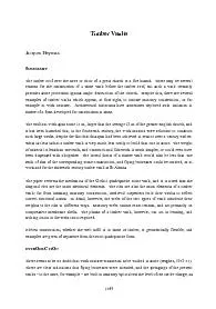
ated examples of timber construction 147imitating148 Gothic masonry but such vaults are scarce for several reasons A stone vault perhaps indicates strength or at least permanence and Bond ID: 211489

ated examples timber construction

Share:

Link:

Embed:

Download Presentation from below link

Download Pdf The PPT/PDF document "at St Alban’s, fig. 1 (Rogers, 1931..." is the property of its rightful owner. Permission is granted to download and print the materials on this web site for personal, non-commercial use only, and to display it on your personal computer provided you do not modify the materials and that you retain all copyright notices contained in the materials. By downloading content from our website, you accept the terms of this agreement.


Presentation Transcript

at St Alban’s, fig. 1 (Rogers, 1931). Above that height the work is in fact entirely in timber, although the visitor may be misled into thinking that the construction is that of a typical masonry lierne vault, developed in England in the first half of the fourteenth century. Indeed, the date of the first timber vault to the nave at York, 1354, fits stylistically into that period; such vaults were essentially still quadripartite, although decorated with increasingly complex patterns of star and mesh liernes. ated examples of timber construction “imitating” Gothic masonry, but such vaults are scarce for several reasons. A stone vault perhaps indicates strength, or at least permanence, and Bond (1906) deplores the use of wood as a pretence: “Whether are objectionable as being a reproduction in one material of forms which arose out of the nature of another”. This view may have been shared by the designers, and by the commissioners, of great medieval churches. Moreover, it was appreciated that a stone vault provided substantial protection against fire. The open timber high roof was, and is, a fire hazard; should a fire start, then a timber vault below the timber roof would provide little protection, and this is a practical, rather than a political or an aesthetic reason, for preferring to build Figure 1. The timber vault (1290) to the Presbytery at St Albans (from Rogers, 1931) The high timber roof above a vault provides protection against rain. By contrast, a masonry vault, whether cracked or not (and it is usually fissured), is relatively porous, and the double roof system is symbiotic; the masonry vault is protected against rain by the high timber roof, and the timber roof 1570 is fireproofed by the masonry vault. Timber vaults were indeed destroyed by fire; the 1354 nave vault at York was burnt down in 1840, and the present construction is a Victorian replacement. Most surviving timber vaults are replacements, although one which has survived is the late thirteenth century vault to the Presbytery of St Alban’s. THE MECHANICS OF MASONRY VAULTS The vault at St Alban’s is strictly quadripartite; it is earlier than those at York, and also smaller, having a span of 11 m compared with some 15 m. (Dimensions are approximate, and given here for comparative purposes. The standard “grid” dimension-centre-line to centre-line of columns, for example – is greater than the clear span of the covering vault by a distance equal to the clerestory walls.) The essential geometry of a quadripartite vault is revealed in a sketch of this construction, fig. 2 (Fitchen, 1961). The “shell” shown in the figure may be taken to have very small thickness, and this is in fact the conceptual model that would be used by a modern engineer using “membrane analysis” to determine the stresses (due to self weight) which are present in the surfaces. Figure 2. Schematic “shell” of the qufrom Fitchen, 1961) The equations which determine the stresses are sensitive to the curvatures of the shell. The surfaces sketched in fig. 2 are, in mathematical terms, developable. That is, a model could be constructed by cutting paper to the required shapes, and bending the pieces to fit together at glued “creases” (the ridge and the diagonal groins). Each of the vaulting surfaces, the webs, is therefore flat in one direction, and curved in the direction at right angles. By contrast, a dome, or a fan vault, cannot be constructed from flat pieces of stretched). Any surface may be described in terms of two curvatures; two (curved) lines drawn on the surface and intersecting at nt curvatures at that point of intersection. For a dome, the curvatures will both be concave when viewed from below (the values will in general be unequal, except for the case of a spherical dome), and the numerical product of the curvatures, the so-called 1571 Gaussian curvature, will be positive. For a fan vault one curvature is convex and one is concave, and the Gaussian curvature is negative. It is a sign of the Gaussian curvature which has a profound effect on the solution of the governing equations. It is not only the mathematics which is affected by the sign of the Gaussian curvature; there are important constructional consequences. For example, a dome, as Brunelleschi demonstrated, can be built with very little centering; a completed horizontal ring of masonry is self-supporting, and serves as a firm base for the next ring to be constructed. Construction may be terminated at any point, and the dome left with a large eye, as in the inmost of Wren’s three domes for St Paul’s, or in the (concrete) Pantheon. By contrast the fan vault (as also the two-dimensional masonry arch) requires support until the final “keystone” is placed – only then may the centering be struck. (It is true that in the final stages of construction of a fan vault, omission of the spandrel bosses will not cause the vault to fall; local dome action will ensure stability in the neighbourhood of such holes.) It is likely that the huge constructional costs of large-span fan vaults, incurred both for stone cutting and for falsework, ensured that they were built for only a decade or so at the start of the sixteenth century. As has been noted, the surfaces of the idealized quadripartite vault have, in one direction, zero curvature, and the Gaussian curvature is therefore also zero. Once again this has important consequences for the solution of the equations. The first and major consequence is that stresses can be propagated unchanged in the “flat” directions, indicated by the straight lines in fig. 2. Now at the edges of the transverse (north/south) vaults, for example, there may be no applied load – and in any case there will exist, potentially or in reality, “Sabouret” cracks isolating the vault completely from the window arch. Thus, in theory, the surfaces in fig. 2 can be completely free of stress in the flat directions; all the forces will follow down the curved directions of the vaulting severies until the groin is reached. Thus simple membrane theory supports Pol Abraham’s view of the way forces are carried in a vault (Abraham, 1934). He imagined a ball rolling down the surfaces – the path taken by the ball indicates the direction of the forces. When the ball reaches the groin, it rolls along this intersection until the buttressing system is reached. Membrane theory indicates a sharp rise in values of stress in the groin region (compared with the ambient values in the vaulting webs), but the values are still low compared with the intrinsic strength of even weak masonry forming the webs. The skeletal diagonal groins emerge as the structure supporting the weight of the vaulting bays, and passing that weight and thrusts to the fliers (if they exist) and the external buttresses. This view of the force system is essentially correct, even through the vault has been idealized in order to provide convenient mathematics. A real vaulting web has finite thickness – still small compared with leading dimensions, but not vanishingly small. Crucially, while the forces must still lie within the two surfaces of the vaulting webs, they are no longer constrained by the straitjacket of 1572 a prescribed mathematical shape; they can depart slightly from the assumed perfect geometry (and indeed the geometry of the vault as built will not be perfect). In two dimensions, Robert Hooke identified the shape of the perfect arch as that of a hanging flexible chain carrying the same loads, but inverted. A circular arch of reasonable thickness can stand because Hooke’s chain, not circular, can be fitted between extrados and intrados of the arch. Similarly, the force paths in the vault need not conform with the centre-line geometry of the idealized vault. Further, the “flat” surfaces may in reality be slightly curved, and forces need no longer be zero in directions at right angles to those of maximum curvature. Nevertheless, primary forces in a quadripartite vault follow the paths of Pol Abraham’s rolling marbles, and Gothic builders had a firm (if non-mathematical) grasp of the mechanics of such vaults. THE RIB The vaulting rib actually predated Gothic but it is certainly thought of as one of the defining ture after 1140 (the Abbey Church of St Denis). Applied just below the groin, it serves as a reinforcement to the intersection of two surfaces. It is not absolutely essential for the stability of a vault, but its presence relieves those high stresses which arise in the webs at their intersections; the diagonal ribs may be viewed as two arches carrying on their backs the total weight of the vaulting webs. The rib has, of course, other functions. Visually, it covers awkward masonry jointing where the webs meet at the groins. Visually again, it serves, architecturally, to articulate the bays of a long nave or choir. But its main structural purpose is to collect the out-of-balance forces which arise when two masonry shells meet and experience an abrupt change of direction. By contrast, a rib applied to a smoothly turning masonry surface – a tierceron or a lierne, for example – is in general purely decorative; such a rib does not in fact collect forces from the vaulting web that it appears to support. Similarly, a horizontal ridge rib (which may indeed not be present) will load the vaulting webs but does not contribute to the strength of the masonry. Equally, transverse ribs (which again may be omitted) define the bays of a vault but do little more than carry their own weights. The intrinsic structural mechanics of the vault, exposed to view in the rib, enabled Gothic builders to construct economically. To vault in masonry a 12 m x 6 m bay of a nave (dimensions typical for a number of English cathedrals), the two diagonal load-bearing ribs were first erected; this of course required timber centering so that the two masonry arches could be built, but the falsework was much less elaborate than that needed for a Romanesque groin vault. Once the diagonal ribs were in place, the stone vaulting webs could be built quickly and easily, with little support required during construction. A logical and efficient system had evolved for the creation of a high masonry vault. The system was also flexible architecturally – the bay had no need to be rectangular, but could be trapezoidal, for example, to conform with a semicircular apse. If need be, more than four load 1573 bearing ribs could meet at the central boss of an apsidal chapel, and Villard, in his notebook of the mid thirteenth century, gives sketches for both of these arrangements. The Gothic builder knew that any reasonable arrangement of ribs would “work”, and an extreme example is the “crazy” vault of St Hugh’s Choir, Lincoln Cathedral (c. 1200), shown schematically in fig. 3. It will be seen that the four “diagonal” ribs do not in fact form diagonals meeting at the centre of the bay, but are instead directed towards the third points – two ribs from one side of the choir meet a single rib from the other side. This single rib is applied to a smoothly curved (flat) surface, and its function is to resist the thrusts from the two ribs that it meets. Figure 3. The “crazy” vault (c. 1200) of Lincoln Cathedral THE MECHANICS OF TIMBER VAULTS As at York, the vault at St Alban’s (c.1290) was conceived as being of masonry; the stone springers, fig. 1, had already been completed. There would have been no constructional difficulty in carrying out the original intention, but a timber vault would have been very much less costly. Stone would have had to have been transported from a distance (the main portions of the Romanesque Abbey Church had been built from recycled material – Roman bricks and rubble masonry), and there would have been expensive centering to support the new stonework. Instead, the heaviest members of the timber vault of fig. 1, the four diagonal ribs, of something over 6 m in length, were each of say 600 kg, and could be lifted easily to meet at the boss at the centre of each bay (in fact, they meet at the ridge rib, and the junction is covered by a hollowed boss). The transverse ribs in each bay structure, and it was a simple matter to nail the 18 mm flat boards to form the webs of the completed vault, which could then be decorated. The intermediate ribs marked X in fig. 1 were added a century and a half later during repair work to the vault; these intermediate supports halve the lengths of the planking needed to form the faces of the transverse barrels. 1574 The timber vault is not “imitating” a masonry prototype. Rather it exposes with great clarity the way such a vault should be built – the function is expressed in the structure, whether the material be stone or wood. The structural forces resulting from the dead weight of the material are collected in the diagonal ribs, and passed through the springers to the buttressing system; since a timber vault might weigh less than a tenth of the corresponding masonry vault, the lateral vault thrust would also be less than a tenth, and the buttressing system would have no need of fliers over the aisles. The whole of a vaulting system is, in structural terms, highly redundant, and there are many different load paths which will ensure stability. It is not possible to state that any particular distribution of forces will be actually present in a vault (or indeed in any other structure), but the analyst can at least present reasonable patterns of behaviour. Pol Abraham’s rolling ball gives a good picture of the way forces are carried in a continuous masonry web; the (pointed) barrels of a regular quadripartite vault act as simple arches supported on the diagonal ribs. Such a force system is, however, unreasonable for the timber vault. The planks cannot be assumed to abut tightly one to another, and there is then no load path from plank to plank down the line of greatest slope. Instead, a plank will be forced to act in bending, as a short-span beam spanning between the main timber members; wood is well able to resist such bending action in a way that would distress a stone and mortar assemblage. Thus masonry vaults may be imagined to pass their loads down the slopes of the webs to diagonal ribs, while timber planks run horizontally across the slopes to the ribs. In both cases, however, the gravity loads depend for their support on the diagonal ribs. Just as for the ribbed masonry vault, the designer in timber had great architectural freedom. In the cloister of Lincoln Cathedral, for example, the entrance to the chapter house has a width which does not conform to the bay spacing on the opposite side of the cloister (Howard and Crossley, 1917). The ribs of the timber vault are therefore locally forced out of a regular quadripartite pattern, and their complex arrangement may be seen, involving for example two ribs on one side meeting a single rib on the other, as in the crazy vault in the same Cathedral, fig.3. ENVOI r English cathedrals is about 12 m, the 15 m of York would not have worried fourteenth century masons. The 1340 Lady Chapel of Ely Cathedral is of almost exactly this size, and other masonry vaults of 15 m or more already existed in France at, for example, Amiens, Beauvais and Rheims. Later, 19 m was achieved at Albi, 20 m at Palma de Mallorca and 23 m at Gerona. For still larger spans the masonry dome was the solution – 33 m for Hagia Sofia, St Paul’s 34 m, St Peter’s Rome and Florence 42 m, and the Pantheon 43 m. In 1340 at Ely, however, the masons may well have had reservations about constructing a 24 m stone vault over the octagon, and the lantern vault is in timber. But at York, as at St Alban’s, it was cost rather than timidity which dictated the use of wood. Figure 4 shows the medieval vault at York 1575 under repair in 1796, before the destructive fire of 1840. The main skeletal structure is somewhat masked by the proliferation of the ribs, but those ribs form an effective armature for the timber shell that will be nailed to their backs. Figure 4. York Minster: the nave vault during repair, Joseph Halfpenny, 1796 (from Brown 2003) REFERENCES Viollet-le-Duc et le rationalisme medieval, Paris, 1934. Gothic architecture in England, London, 1906. Brown, Sarah. York Minster: An architectural history, 1220-1500, English Heritage Publications, 2003. Fitchen, J. The construction of Gothic cathedrals, Oxford, 1961. Howard, F. E. and Crossley, F. H. English church woodwork, London, (n. d. but 1917). . 1576