/
Freescale Semiconductor Errata   Freescale Semiconductor Inc Freescale Semiconductor Errata   Freescale Semiconductor Inc

Freescale Semiconductor Errata Freescale Semiconductor Inc - PDF document

tatyana-admore
tatyana-admore . @tatyana-admore
Follow
471 views
Uploaded On 2014-11-30

Freescale Semiconductor Errata Freescale Semiconductor Inc - PPT Presentation

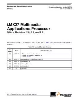
All rights reserved This document details all known silicon errata for the iMX27 Table 1 provides a revision history for this document Table 1 Document Revision History Rev Number Date Substantive Changes 06 102012 Added errata 11 12 13 and 14 Upd ID: 19045

All rights reserved This

Share:

Link:

Embed:

Download Presentation from below link

Download Pdf The PPT/PDF document "Freescale Semiconductor Errata Freesca..." is the property of its rightful owner. Permission is granted to download and print the materials on this web site for personal, non-commercial use only, and to display it on your personal computer provided you do not modify the materials and that you retain all copyright notices contained in the materials. By downloading content from our website, you accept the terms of this agreement.


Presentation Transcript

Freescale SemiconductorErrata ©2012 Freescale Semiconductor, Inc. All rights reserved. This document details all known silicon errata for the i.MX27. Table1 provides a revision history for this Table1. Document Revision HistoryRev. DateSubstantive Change(s)0.610/2012 •Added errata 11, 12, 13, and 14. Document Number:MCIMX27CERev. 0.6, 11/2012i.MX27 Multimedia Applications ProcessorSilicon Revision: 2.0, 2.1, and 2.2 i.MX27 Multimedia Applications Processor,Rev. 0.6Freescale SemiconductorTable2 defines severity values for errata described in this document.Table3 provides the silicon revision and equivalent mask set and product number contained within this errata document.Table2. Definitions of Errata SeveritySeverityErrata TypeDefinitionWorkaround 1 Critical Failure mode that severely inhibits the use of the device for all or a majority of intended applications Unavailable High Failure mode that might restrict or limit the use of the device for all or a majority of intended applications Generally available3ModerateUnexpected behavior that does not cause significant problems for the intended applications of the deviceGenerally availableTable3. Silicon Revision to Mask Set CorrelationSilicon RevisionMask SetProduct Number2.0 0M72JMCIMX272.1M72JMCIMX272.2M72JMCIMX27 i.MX27 Multimedia Applications Processor,Rev. 0.6Freescale SemiconductorTable4 provides the known chip errata affecting silicon version 2.0, 2.1, and 2.2 of the i.MX27 Multimedia Applications Processor.Table4. Chip Errata for i.MX27NumberSeverityErratumSummaryDetails1.3bo57692Module Affected: Video CodecTitle: Video Codec module supporting MV and MVD ranges does not conform with standard.Description: Video Codec module supporting MV and MVD ranges does not conform with the H.264 standard. The standard specifies the range of MVD to be –4096to4095.75. However, the Video Codec module only supports up to –2048–2047.75. The standard specifies that the range of horizontal MV to be –2048to2047.75. However, the Video Codec module only supports up to –1024to1023.75. Because the maximum image resolution in the i.MX27 device is 720576, it is not likely to receive a bitstream with MV/MVD in such a large range in real codec applications; therefore, there is no real impact to applications.Workaround: No workaroundFix Plan/Status: No fix planned2.3bo58229Module Affected: Title: A remote wake-up can be interpreted as a disconnect.Description: In Host mode in the ULPI core, a remote wake-up can be interpreted as a disconnect. This issue involves the latency when asserting in synchronous mode. In some instances, the host will not properly latch the K state. When this occurs, the core wakes up to a J state. Eventually the host will not resume, and will show an SE0 and assume a disconnect occurred.Workaround: No workaroundFix Plan/Status: No fix planned3.3bo57815Module Affected: WEIMTitle: A burst write access will miss the first word when the burst write follows another burst operation.Description: When a burst access to WEIM external memory is immediately followed by another burst access, the first word may be missed at write-burst access because the eb_b signal comes too late.Reason:The ecb_hburst_ecb_fw signal in the WEIM Bus Controller module has an extra-high pulse, and only one high pulse is required.Workaround: Set EDC field to two breaks, which continues the burst access to external memory.Fix Plan/Status:No fix planned i.MX27 Multimedia Applications Processor,Rev. 0.6Freescale Semiconductor4.2bo93263Modules Affected: Video CodecTitle: Lockup of Video Codec in MPEG-4 encode or decodeNote:Applies only to silicon revision 2.0Description: During encoding or decoding MPEG-4, the Video Codec module can lock up. In the combined AXI to AHB and 32–64 gasket, there is a FIFO for read data, which buffers data that is coming from the 64-bit bus faster than the 32-bit bus can accept it. There is no logic to send a request to memory only when the FIFO has room for return data. In a case with ideal data throughput, this FIFO overruns and read data is corrupted. This ideal data throughput only happens during MPEG-4 encoding and decoding.Workarounds: Set the Latency Hiding Disable (LHD) bit in the ESDCTL DDR Controller ESDMISC register. This adds latency between DDR transactions, removing the ideal data throughput. This should only be done during MPEG-4 encoding and decoding. Note that this reduces performance.During MPEG-4 encoding/decoding, this degradation is acceptable. LHD should not be set during H.264 or H.263 operation. Assign all buffers accessed by the video code into the same DRAM bank and ensure every buffer type has a size of integer number of pages. This ensures that there is a page miss between accesses of different sub-masters inside the VPU, increasing the delay. The DRAM is split into four equal sizes called banks, so the bank size is 1/4 of the DRAM size.Fix Plan/Status: Fixed in silicon revision 2.15.3bo93708Module Affected: JTAG ControllerTitle: Boundary scan fails because of an internal timing issue.Note:Applies only to silicon revision 2.0Description: Timing is not properly extracted for the boundary scan circuitry so post-layout gate-level simulations did not correctly simulate the circuit. A race condition prevents proper shifting of data through the Boundary Scan circuitry.Workaround: NoneFix Plan/Status: Fixed in silicon revision 2.1Table4. Chip Errata for i.MX27 (continued)NumberSeverityErratumSummaryDetails i.MX27 Multimedia Applications Processor,Rev. 0.6Freescale Semiconductor6.2bo95933Module Affected: Title: When the incorrect power-up or power-down sequence is used on the processor, unintentional programming of IIM fuses is possible, regardless of the set FuseVDDvoltage, reconfiguring the part permanently.Description: Internal fuses on the processor could be unintentionally programmed, regardless of the voltage level set for FuseVDD. Even if FuseVDDis set to 1.8 V (read-only voltage), some processors may be programmed at that voltage. This only happens when the incorrect power-up or power-down sequence is used on the processor.Workaround: It is recommended to power up and power-down the processor following the power-up and power-down sequence documented in the MCIMX27 Multimedia Applications Processor DataSheetFix Plan/Status: No fix planned7.2—Module Affected: eMMA PP (PostProcessor)Title: Resize fails when the horizontal scale is bigger than two.Description: The gasket that is between the Post Processor and the EMI cannot support burst accesses when the burst length is equal to or over 16 words. However, the Post Processor will do the burst access over 16 words when it resizes with the horizontal scale over 2. In this case, the Post Processor's access misses the data or will be pending due to no response from the gasket.Workaround: Use software for horizontal resizing when the scale is bigger than two. For example, when the scale is 2.5 for both horizontal and vertical, software should be used to produce the horizontal resize with scale 2, and the Post Processor should do the vertical 2.5 and horizontal 1.25 resize.Fix Plan/Status:No fix plannedTable4. Chip Errata for i.MX27 (continued)NumberSeverityErratumSummaryDetails i.MX27 Multimedia Applications Processor,Rev. 0.6Freescale Semiconductor8.3ENGcm11270Module Affected:WEIMTitle: AUSx bits do not work for address bit A[23].Note:The AUS feature is not only for ADDR[25:16] (Address Bus MSB), but also for ADDR[15:0] (Multiplexed Address Bus LSB).Description: The AUS bits in the WEIM Configuration Register (WCR) do not work for the address bus bit A[23]. The WEIM address bus’ most significant bits (ADDR[25:16], Address Bus MSB) are used for address bits [25:16]. If the corresponding AUSx bit (each WEIM chip select has a corresponding AUS bit) is set to 1 in the WCR register, then these MSB signals reflect the AHB address bits [25:16]. If the AUSx bit is set to 0, then these signals should represent AHB address bits [27:18] for word width memory, [26:17] for half word width memory, and [25:16] for byte-width memory. The error occurs when the AUSx bit is set to 1, which causes the A[23] bit to not match the correct value of the corresponding AHB address bit.Reason:This errata affects all Chip-Select regions (that is, CS0–CS5). You cannot use the WEIM AUS feature to use un-shifted address mode if address bit A[23] is needed to address the external memory device. Workaround:Set AUSx to 0, if address bit A[23] is needed to address the external device.Fix Plan/Status: No fix plannedTable4. Chip Errata for i.MX27 (continued)NumberSeverityErratumSummaryDetails i.MX27 Multimedia Applications Processor,Rev. 0.6Freescale Semiconductor9.2ENGcm11409Module Affected:WEIMTitle: In FCE=1 mode, WEIM cannot correctly sample the data if there is ECB asserted during burst accessDescription:End current burst (WAIT). This active-low input signal ECB is asserted by external burst capable devices. It is serviced only in synchronous mode (SYNC=1).This signal can be used in the following modes depending on the EW bit in the Chip Select Control Register. In the ECB mode (EW=0), ECB indicates the end of the current (continuous) burst sequence. Following assertion, the WEIM terminates the current burst sequence and initiates a new one. In the WAIT mode (EW=1), the memory device asserts this signal to insert WAIT states during refresh collisions or during a row boundary crossing. Following assertion, the WEIM does not terminate the current burst sequence and continues it once WAIT is negated.FCE is a parameter in the register CSCRxA that is used to enable or disable feedback clock: If FCE=0, WEIM samples the data by internal AHB bus clock. If FCE=1, WEIM samples the data by BCLK_FB signal that is from PAD. If FCE is configured to 1 and there is ECB assertion during access, WEIM does not sample the correct data.Reason: You cannot use FCE=1 mode when there is ECB assertion during access.Workaround: If external device asserts ECB_B signal during burst access in FCE=1 mode, use FCE=0 mode instead.Fix Plan/Status: No fix plannedTable4. Chip Errata for i.MX27 (continued)NumberSeverityErratumSummaryDetails i.MX27 Multimedia Applications Processor,Rev. 0.6Freescale Semiconductor10.2ENGcm11563Module Affected: PLLTitle: Boot problem due to improper clock duty cycleNote:Systems that use 266 MHz are not affected by this bug.Description: There is a design errata in the i.MX27 PLL/DIV design, which causes the ARM_CLK to have an incorrect duty cycle. The root cause of this issue is due to an uninitialized node in the PLL, clock gating, and divider circuitry, so the probability of this issue is random. This error causes the ARM™ and DDR clocks duty cycle to be 66% when they are running at 266MHz and 75% when at 399MHz, instead of 50%.Projected Impact: The result of the incorrect duty cycle of the clock is that the ARM core might halt. This issue affects systems that enable 399 MHz for the ARM core. Workarounds:There are both a hardware and a software workaround. To guarantee correct operation, the software workaround should only be applied to devices that have had the new PLL test applied. The test will be applied from a date code 1105:Workaround 1—HardwareKeep MPLLVDD200mV during the initial part of the power-up sequence and delay the MPLLVDD supply with respect to QVDD, NVDD5, and AVDD. See Figure1 for a recommended power-up sequence. This workaround sets the uninitialized node to the correct state enabling the appropriate 399MHz clock output duty cycle. For the clock switching errata workaround, the following conditions must be satisfied: –QVDD must be powered up before MPLLVDD.–NVCC5 must be powered up before MPLLVDD. (This is required for the POR_B signal to propagate to the clock gating logic.)–AVDD must be powered up before MPLLVDD. (This is required for the POR_B signal to propagate to the clock gating logic.)–MPLLVDD must be driven to 0, not floating, before powering upA suggested delay circuit is described in Figure2Workaround 2—SoftwareOriginally for the ARM clock to work at 400MHz, the MPLL is configured for 800-MHz operating frequency at the 2x Clock Port (see Figure3 and code that follows the figure), and the DIV2 divider is selected by software to achieve the 400-MHz operating frequency at the ARM core. The default 266-MHz frequency is achieved by using the DIV3 divider with an 800-MHz frequency at the 2x Clock Port (so 400-MHz MPLL frequency).The intent of this workaround is to reconfigure the 2x Clock Port to 1.2GHz (600-MHz MPLL frequency), and continue to use the DIV3 divider in order to achieve the 400-MHz operating frequency. This avoids switching to the DIV2 divider, which introduced the problem.Fix Plan/Status:No fix plannedSee continuation of this erratum on p. 12.Table4. Chip Errata for i.MX27 (continued)NumberSeverityErratumSummaryDetails i.MX27 Multimedia Applications Processor,Rev. 0.6Freescale Semiconductor11TLSbo94561Module Affected:Title: Read access to Clock Controller SPCTL0 register clears it Description:Any read access from the Clock Controller Module SPCTL0 register will clear the contents of the register.Projected Impact:For silicon revision 2.0 and prior, any read access performed from the Clock Controller Module SPCTL0 register will clear the contents of the register.Workaround:The SPCTL0 register needs to be re-programmed after each read access: either with a new value, or with the same value that was just read.Projected Solution:Fixed in silicon revision 2.1.12TLSbo95476Module Affected:Title: LSCLK is missingDescription:In 4 bpp, 8 bpp, 18 bpp, and TFT modes, LSCLK is missed in these conditions: One clock cycle before every OE_ACD assert timing Every VSYNC rising timing Every VSYNC falling timingProjected Impact:If the user connects LSCLK directly with LCD panel and the LCD panel allows missing clock,then, there is no issue. However, if the user adds a serializer between LSCLK and LCD panel, then,the serializer may not work correctly because of missing clock and the LCD panel may have noise.Workaround:Connect LSCLK directly with LCD panel, if the LCD panel allows it.Projected Solution:No fix scheduled.Table4. Chip Errata for i.MX27 (continued)NumberSeverityErratumSummaryDetails i.MX27 Multimedia Applications Processor,Rev. 0.6Freescale Semiconductor13ENGcm12387Module Affected: PLLTitle: MPLL restart limitation. Applies only to silicon rev. 2.2.Description: There is a limitation in the i.MX27 CCM module of the latest i. MX27 silicon (rev 2.2). This limitation requires that the MPLL can only be restarted under the following conditions: CSCR register bit fields: ARMSRC == 1 and ARMDIV[1:0] == 00 (meaningARM_CLK is divided by 2 from MPLL_CLK) CSCR register bit fields ARMSRC == 0 and ARMDIV[1:0] == 00 (meaning ARM_CLK is divided by 3) AND MPLL output is greater than 537 MHz.The ARMSRC and ARMDIV bits can be configured to any value required by the application immediately after the MPLL restart.Workaround: Make sure either of the following two conditions are satisfied when MPLL is restarted: ARMSRC == 1 and ARMDIV[1:0] == 00 ARMSRC == 0 and ARMDIV=[1:0] == 00 AND MP�LL = 537 MHzTable4. Chip Errata for i.MX27 (continued)NumberSeverityErratumSummaryDetails i.MX27 Multimedia Applications Processor,Rev. 0.6Freescale Semiconductor14ENGcm12388Module Affected: PLLTitle: MPLL reference clock source change following a warm reset.Description:A “warm” reset is a reset initiated by a watchdog timeout, RESET_IN, or by software forcing a reset via the watchdog module. Such a reset will reconfigure all the CCM registers to their default values but it will not restart the MPLL, so the full CCM configuration defined by the registers does not take effect. In particular, MCU_SEL is cleared, selecting the internal FPM output. Changes to ARMSRC and ARMDIV also take immediate effect. As a consequence, if the external high frequency reference clock is slower than the internal FPM output, and the MPLL has been configured to operate at 1.2GHz, the MPLL will exceed the specified limite of 1.2GHz. For example: Given an external high frequency clock of 24MHz, a low frequency clock of 32kHz, and the MPLL configured for 1.2GHz (MF=50) using the external 24-MHz clock as the reference, the following will occur: After a warm reset, the MPLL will continue using MF=50, because the CCM registers are reset to default values but the PLLs are not restarted. As a result, the MPLL will lock to the FPM output (32.768MHz, selected by the default value of MCU_SEL in CSCR), driving MPLL output frequency to 1.64GHz, which is beyond the specified maximum.Workarounds:1)Reconfigure the MPLL prior to a warm reset to avoid exceeding the 1.2-GHz maximum MPLL output frequency. This workaround only works when warm resets can be anticipated.2)In applications that cannot anticipate a warm reset, as in the case of RESET_IN from somewhere else in the system or a watchdog timeout, the MPLL should be operated at a sufficiently lower frequency so as to prevent a warm reset causing the MPLL to exceed 1.2GHz. 3)The CLKMODE[1:0] pads may be used to bypass the FPM and MPLL thereby preventing the PLL from being overclocked.Table4. Chip Errata for i.MX27 (continued)NumberSeverityErratumSummaryDetails i.MX27 Multimedia Applications Processor,Rev. 0.6Freescale Semiconductor(Continued from erratum 10, ID ENGcm11563)QVDD, AVDD (IO power for BOOT pin), NVDD5 (IO power for POR_B pin) must be powered up before MPLLVDD. MPLLVDD must be driven to 0, not floating, before powering up.NVDD supply domain (except for NVDD5) can be turned on either at the same time as MPLLVDD or with NVDD5Figure1. Recommended Power-Up SequenceFigure2. Recommended Hardware Fix if QVDD and MPLLVDD are Ganged i.MX27 Multimedia Applications Processor,Rev. 0.6Freescale SemiconductorSee the code following this figure.Figure3. i.MX27 Clock ArchitectureFirmware:The following code provides guidance for setting the MPLL to the new setting (600MHz) that equates to an output of 1.2GHz at the 2x Clock Port.//Clock Test ProgramProgram ExplanationThe ARM clock frequency is output at the CLKO pin of the i.MX27, this frequency has been divided by 4 at this pin for an easier monitoring. If it is desired to see the full 400MHz atthis pin, the line reg32_CRM_PCDR0 |= 0xC00000; must be commented.The program is initially configured to use the external 32.768KHz oscillator as source of the MPLL. If it is desired to use the external 26MHz oscillator as source, the followingsteps must be followed:- Comment the reg32_CRM_CSCR &= ~bit16; line- Uncomment the //reg32_CRM_CSCR |= bit16; line- Comment the reg32_CRM_MPCTL0 = 0x00322030; line- Uncomment the //reg32_CRM_MPCTL0 = 0x00262C15; lineThe DIV3 divider is selected by means of the ARM SRC bit in register CSCRThen the divided by 3 frequency is divided by 1 to get the ARM clock frequencyFinally, the 1.2GHz is programmed at the 2x Clock Port and the MPLL is restarted for the ARM to start running at 400MHzNotes:- fdpll = 2 * fref * (MFI + MFN / (MFD + 1)) / (PD + 1)- MPLL Restart (CSCR, bit 18) restarts MPLL at the new assigned frequency. MPLL_RESTART self-clears after 1 (min) or 2 (max) cycles of CLK32- CSCR register bit 16 (MCU_SEL) should be changed to 1 to select 26MHz external clock source- CSCR bit 15 (ARM_SRC) selects the ARM clock source (0 = DIV3) i.MX27 Multimedia Applications Processor,Rev. 0.6Freescale Semiconductor- CSCR bits 13-12 (ARM_DIV) set the divider for ARM clk (00 = Divide by 1)- CSCR bit 4 divides 26M oscillator by 1 or 1.5 (no need to change, default is divide by 1)- CLKO_SEL (bits 0-4 of register CCSR) select output at CLKO pin. 00011 is MPLL reference clk#include tdio.h&#xs-27;#include "common.h"typedef volatile unsigned short Un16;typedef Un16 * P_Un16;/* unsigned 16 bit data */typedef volatile unsigned int Un32;typedef Un32 * P_Un32;/* unsigned 32 bit data */#ifndef CRM_CSCR_BASE_ADDR#define CRM_CSCR_BASE_ADDR (0x10027000)#endif#define reg32_CRM_CSCR (*(P_Un32)(CRM_CSCR_BASE_ADDR+0x00)) // 32bit Clock Source Control Reg#define reg32_CRM_MPCTL0 (*(P_Un32)(CRM_CSCR_BASE_ADDR+0x04)) // 32bit MCU PLL Control Reg#define reg32_CRM_MPCTL1 (*(P_Un32)(CRM_CSCR_BASE_ADDR+0x08)) // 32bit MCU PLL#define reg32_CRM_SPCTL0 (*(P_Un32)(CRM_CSCR_BASE_ADDR+0x0C)) // 32bit Serial Peripheral PLL Ctrl 0#define reg32_CRM_SPCTL1 (*(P_Un32)(CRM_CSCR_BASE_ADDR+0x10)) // 32bit Serial Peripheral PLL Ctrl 1#define reg32_CRM_OSC26MCTL (*(P_Un32)(CRM_CSCR_BASE_ADDR+0x14)) // 32bit Osc 26M register#define reg32_CRM_PCDR0 (*(P_Un32)(CRM_CSCR_BASE_ADDR+0x18)) // 32bit Serial Peripheral Clk Div Reg 0#define reg32_CRM_PCDR1 (*(P_Un32)(CRM_CSCR_BASE_ADDR+0x1C)) // 32bit Serial Peripheral Clk Div Reg 1#define reg32_CRM_PCCR0 (*(P_Un32)(CRM_CSCR_BASE_ADDR+0x20)) // 32bit Peripheral Clk Control Reg 0#define reg32_CRM_PCCR1 (*(P_Un32)(CRM_CSCR_BASE_ADDR+0x24)) // 32bit Peripheral Clk Control Reg 1#define reg32_CRM_CCSR (*(P_Un32)(CRM_CSCR_BASE_ADDR+0x28)) // 32bit Clock Control Status Reg#define reg32_CRM_PMCTL (*(P_Un32)(CRM_CSCR_BASE_ADDR+0x2C)) // 32bit PMOS Control Reg#define reg32_CRM_PMCOUNT (*(P_Un32)(CRM_CSCR_BASE_ADDR+0x30)) // 32bit PMOS Counter Reg#define reg32_CRM_WKGDCTL (*(P_Un32)(CRM_CSCR_BASE_ADDR+0x34)) // 32bit Wakeup Guard Mode Control Regvoid freq_config ()reg32_CRM_CSCR &= ~bit16;// 32.768KHz external oscillator selected//reg32_CRM_CSCR |= bit16;// 26MHz external oscillator selected//reg32_CRM_CSCR &= ~bit15;// ARM_SCR (bit 15 in register CSCR) selects between DIV2 or DIV3 dividers, this line leaves the default setting (DIV3)reg32_CRM_CSCR &= 0xFFFFCFFF;// ARM_DIV = divide by 1reg32_CRM_CSCR &= 0xFF0FFFFF;// SPLL clock source selected for SSI, H264 and MSHC//1. Program the desired values of PD, MFD, MFI, and MFN into the MPCTL0.//reg32_CRM_MPCTL0 = 0x00211803;// Default, MPLL = 399MHz @ 32KHz//reg32_CRM_MPCTL0 = 0x01EF15D5;// MPLL = 399MHz @ 32.768KHz i.MX27 Multimedia Applications Processor,Rev. 0.6Freescale Semiconductor//reg32_CRM_MPCTL0 = 0x00331C23;// MPLL = 399MHz @ 26MHzreg32_CRM_MPCTL0 = 0x00322030;// MPLL = 600MHz @ 32.768KHz//reg32_CRM_MPCTL0 = 0x00262C15;// MPLL = 600MHz @ 26MHz//2. Set the MPLL_RESTART bit in the CSCR (it will self-clear).reg32_CRM_CSCR |= bit18;// New frequency setting takes effect now//3. New MPLL settings will take effect.//4. The new PLL clock output is valid upon the assertion of the DPLL lock flag.int main ()printf ("Start test\n");//reg32_CRM_CCSR &= 0x00;// DPLL, FPM, OSC26M bypassedreg32_CRM_PCDR0 |= 0xC00000;// CLKO Divided by 4reg32_CRM_CCSR = 0x317;// Output MPLL reference clock at CLKO pinprintf ("Frequency output at CLKO\n");freq_config ();printf ("Frequency changed\n"); Document Number:MCIMX27CERev. 0.611/2012 Information in this document is provided solely to enable system and software implementers to use Freescale products. There are no express or implied copyright licenses granted hereunder to design or fabricate any integrated circuits based on the information in this document.Freescale reserves the right to make changes without further notice to any products herein. Freescale makes no warranty, representation, or guarantee regarding the suitability of its products for any particular purpose, nor does Freescale assume any liability arising out of the application or use of any product or circuit, and specifically disclaims any and all liability, including without limitation consequential or incidental damages. “Typical” parameters that may be provided in Freescale data sheets and/or specifications can and do vary in different applications, and actual performance may vary over time. All operating parameters, including “typicals,” must be validated for each customer application by customer’s technical experts. Freescale does not convey any license under its patent rights nor the rights of others. Freescale sells products pursuant to standard terms and conditions of sale, which can be found at the following address: freescale.com/SalesTermsandConditions.How to Reach Us:Home Page: freescale.com Web Support: freescale.com/supportFreescale and the Freescale logo, are trademarks of Freescale Semiconductor, Inc., Reg. U.S. Pat. & Tm. Off. All other product or service names are the property of their respective owners. ARM is the registered trademark of ARM Limited. © 2012 Freescale Semiconductor, Inc.