PDF-PrimeTime Mode MergingReducing Analysis Cost for Multimode DesignsAuth
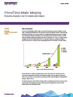
90nmModes65nmScenario increase40nm
150
Corners
Scenarios
Figure 1 Mode and Scenario Increases
White Paper
For signoff purposes these different congurations are typically
Download Presentation
"PrimeTime Mode MergingReducing Analysis Cost for Multimode D " is the property of its rightful owner. Permission is granted to download and print materials on this website for personal, non-commercial use only, provided you retain all copyright notices. By downloading content from our website, you accept the terms of this agreement.
Presentation Transcript
Transcript not available.