/
US Department of Transportation Federal Aviation Admin US Department of Transportation Federal Aviation Admin

US Department of Transportation Federal Aviation Admin - PDF document

tatyana-admore
tatyana-admore . @tatyana-admore
Follow
429 views
Uploaded On 2015-04-30

US Department of Transportation Federal Aviation Admin - PPT Presentation

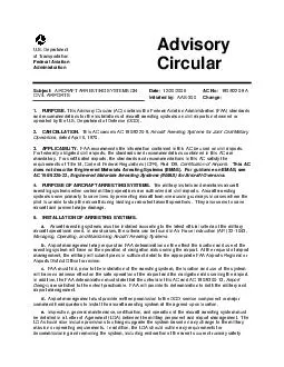
S Department of Transportation Federal Aviation Administration Advisory Circular Subject AIRCRAFT ARRESTING SYSTEMS ON CIVIL AIRPORTS Date 12202006 Initiated by AAS 300 AC No 1505220 9A Change 1 PURPOSE Th ID: 57843

Department Transportation Federal

Share:

Link:

Embed:

Download Presentation from below link

Download Pdf The PPT/PDF document "US Department of Transportation Federal ..." is the property of its rightful owner. Permission is granted to download and print the materials on this web site for personal, non-commercial use only, and to display it on your personal computer provided you do not modify the materials and that you retain all copyright notices contained in the materials. By downloading content from our website, you accept the terms of this agreement.


Presentation Transcript

U.S. Department of Transportation Federal Aviation Administration Advisory Circular Subject: AIRCRAFT ARRESTING SYSTEMS ON CIVIL AIRPORTS 12/20/2006 Initiated by: AAS - 300 AC No: 150/5220 - 9A Change: PURPOSE. is Advisory Circular (AC) contains the Federal Aviation Administration (FAA) standards AC 150/5220 - 9A 12/20/2006 2 area standards. There is no specified format for this LOA between the military and airport management. At Part 139 - certificated air ports, this LOA must be included in the Airport Certification Manual (ACM). 6. GENERAL INFORMATION. a. The location of the aircraft arresting system on a civil airport is considered fixed by its function. To the extent practicable, the frangibility requiremen ts found in Part 139 must be satisfied. In situations where some components of the aircraft arresting system cannot satisfy frangibility requirements, the safe and proper operation of these components, and only these components, will take precedence over the frangibility requirements. When the arresting system is installed according to U.S. Military criteria, it will not be viewed as a violation of Part 139. b. The airport design criteria found in AC 150/5300 - 13 should be followed to the extent practicable. Grading and site layout criteria in the immediate area of the arresting system will follow the guidance in AFI 32 - 1043. For example, a 1 - vertical to 30 - horizontal ground gradient can be used for the backfill area around the fairlead beam of a BAK - 12 Aircr aft Arresting System, as described in AFI 32 - 1043. 7. PERMANENT INSTALLATIONS. Permanently installed arresting systems should only be allowed when there is a valid military requirement (normally based on the type of military aircraft assigned at the airport) . This requirement should be documented in an LOA between the DOD service component or major command headquarters and the airport owner. At a Part 139 - certificated airport, the LOA must be included in the ACM. When the arresting system is no longer need ed at an airport, it should be removed, and the runway safety area should be restored to the current FAA airport design standards. 8. TEMPORARY ARRESTING GEAR INSTALLATION. a. IN A RUNWAY SAFETY AREA (RSA). The threshold needs to be moved or relocated to provid e the required safety area between the arresting gear and the threshold if the runway is to remain open to civil aircraft for the amount of time the temporary installation is in place. During this period, the new threshold will need to be marked and lighte d in the following manner: (1) Mark the threshold bar with a painted white bar in the grass on each side of the new or relocated threshold. (This can be made from plywood sheets or equivalent materials on each side of the runway to provide an 8 - foot by 24 - f oot threshold bar to satisfy this requirement.) (2) Install yellow painted chevron(s) before the threshold bars on each side of the runway. (This can be made from plywood sheets or equivalent materials. Each chevron can consist of three 4 - foot by 8 - foot sheet s of plywood with one sheet cut diagonally in half to form the point of the chevron. The chevrons will also need to be securely anchored to the ground. Anchoring can be done with spikes.) (3) Cover the Runway Distance Remaining Signs (DRSs) for the opposite d irection from the relocated threshold. (4) Place any Precision Approach Path Indicators ( PAPIs), Visual Approach Slope Indicator s (VASIs), Runway End Identification Lights (REILs), or approach lights systems for the relocated runway threshold end out of servi ce. (5) If night operations will be conducted on the runway, install threshold/runway end lights at the relocated threshold. (6) Adjust the yellow caution zone runway edge lights for the opposite direction to accommodate the new threshold (if applicable). (7) Place ru nway centerline lights for the opposite direction out of service. (8) Cover or place out of service the runway edge lights and threshold/runway edge lights in the relocated area. If the relocated area will be used for taxiing operations at night, taxiway refl ectors will need to be installed. (9) Airport management should coordinate with the FAA offices (Air Traffic, Flight Standards, and Airports District Office) to determine the effect the temporary arresting equipment will have on civil aircraft operations. 12/20/2 006 AC 150/5220 - 9A 3 b. E XCE PTION. The runway threshold does not need to be relocated if a Mobile Aircraft Arresting System (MAAS or a BAK - 12) is installed in accordance with the following: (1) The fairlead beam installation is used, and the MAAS energy absorbers are located outsid e the RSA. (2) To the extent practicable, all arresting system components within the RSA are below grade and covered, and the deck sheaves are covered, ramped, and compacted to a 30 to1 (horizontal to vertical) ratio. Nothing in this subparagraph is inte nded to compromise the safe use or proper maintenance of any arresting system component located in the RSA. (3) The aircraft arresting cable is removed when not required for military operations. 9. NOTICE REQUIREMENT FOR ALL INSTALLATIONS. Airports wher e aircraft arresting systems are installed should include the type, number, and location of arresting system(s) in the Airport Data System [Airport/Facility Directory (A/FD) or Flight Information Publications through the FAA Form 5010 - 1, Airport Master Rec ord, and/or Notice to Airmen (NOTAM) systems]. 10. RUNWAY PAVEMENT MARKING. The location of a permanent aircraft arresting system that crosses operational runway pavement will be identified by a series of reflective circles 10 feet (3.05 meters) in diam eter and painted solid yellow (striated marking will not be allowed) on the runway. The circles will be 15 feet (4.57 meters) apart from edge to edge and extend the full width of the runway. The middle two circles will straddle the runway centerline. Se e Figure 1. When interference occurs with any runway markings, except for runway designation markings, the runway markings may be interrupted with a clearance of 1 foot (0.30 meters) to the edge of the discs. If possible, the aircraft arresting system sh ould Figure 1. Arresting System Runway Pavement Marki ng . ARRESTING SYSTEM WARNING MARKING ARRANGEMENT WHEN SACRIFICIAL PANELS ARE USED PENDANT 5’ (1.52m) RADIUS SEMI - CIRCLES SACRIFICIAL POLYETHYLENE PANELS RUNWAY CENTERLINE SIDE STRIPE SIDE STRIPE CENTERLINE STRIPE 7.5’ (2.29m) 15’ (4.57m) 10’ (3.05m) 10’ (3.05m) 10’ (3.05m) DIAMETER DISCS 5’ (1.52m) 15’ (4.57m) ARRESTING SYSTEM WARNING MARKING ARRANGEMENT WHEN SACRIFICIAL PANELS ARE USED PENDANT 5’ (1.52m) RADIUS SEMI - CIRCLES SACRIFICIAL POLYETHYLENE PANELS RUNWAY CENTERLINE SIDE STRIPE SIDE STRIPE CENTERLINE STRIPE 7.5’ (2.29m) 15’ (4.57m) 10’ (3.05m) 10’ (3.05m) 10’ (3.05m) DIAMETER DISCS 5’ (1.52m) 15’ (4.57m) AC 150/5220 - 9A 12/20/2006 4 be located to avoid any runway marking interference. All other runway markings are to be in compliance with AC 150/5340 - 1, Standards for Airport Markings. 11. ARRESTING SYSTEM SIGNAGE. a. Purpose. Arresting Gear Markers (AGMs) identify arresting ge ar pendant cables or systems on the operational runway surface. See Figure 2. b. Installation. Arresting pendant cables must be identified by AGMs on both sides of the runway. The AGMs are located in line with the pendant cable +/ - 10 feet (3 meters) and equidistant from the runway edge. Where Distance Remaining Signs (DRSs ) (Figure 3) are installed along a runway , locate the AGMs in line with the DRSs, except where the pendant cable is within 20 feet (6 meters) of a DRS. In this case, relocate the AGM 5 feet (1.5 meters) outboard of the DRS. The distance indicated is to the inside edge of the marker. If the arresting gear is in the stopway or runway safety area, signs are not allowed but obstruction lights are required. ( This is a common requirement f or the BAK - 15.) Markers are oriented perpendicular to the runway centerline. Typical installation of an AGM is shown in Figure 4. c. Message . The AGM has a yellow translucent circle approximately 39 inches (1 meter) in diameter facing both runway direction s. d. Dimensions. The AGMs are double faced, internally lighted, with retroreflective message faces that meet the color and reflectivity requirements of ASTM D 4956, Type I Sheeting. AGMs are similar to Size 4 Runway Distance Remaining Signs, as describ ed in AC 150/5345 - 44, Specifications for Runway and Taxiway Signs . Additionally, the AGM should meet the wind - load and frangibility requirements of an L - 858B sign. The spacing, stroke, and shape of legend characters, numerals, and symbols must be in acco rdance with Appendix 1 of AC 150/5345 - 44. A Size 4 sign has a marker panel height of 48 inches (1220 millimeters) and overall mounting height of 54 to 60 inches (1370 to 1520 millimeters). As with the DRS, the AGM should provide at least 12 inches (30 ce ntimeters) of clearance between the top of the sign and any part of the most critical aircraft expected to use the runway when the aircraft wheels are at the pavement edge. e. Electrical . The AGM installation must be compatible with the existing airfield ele ctrical system. The AGMs should be powered from the same source and circuit as DRSs. Figure 2. Arresting Gear Marker (AGM). AGMs have characteristics of Runway Distance Remaining Signs but with a yellow circle 39 inches (1 meter) in diameter on a black background. Figure 3. Runway Distance Remaining Sign (DRS). A DRS is Type L - 8 58B, with a white legend on a black background and conforming to AC 150/5345 - 44, Size 4, Style 2 or 3. 12/20/2 006 AC 150/5220 - 9A 5 12. REFERENCES. Please refer to the current versions of the following documents. FAA ACs are available at http://www.faa.gov/airports_airtraffic/airports/resources/advi sory_circulars/ . Air Force Instructions are available at http://www.e - publishing.af.mil / . a. Title 14, Code of Federal Regulations (CFR), Part 139, Certification of Airports ( http://ecfr.gpoaccess.gov/ ). b. Air Force Instruction 32 - 1043, Managing, Operating, a nd Maintaining Aircraft Arresting Systems . c. Advisory Circular 150/5300 - 13, Airport Design . d. Advisory Circular 150/5340 - 1, Standards for Airport Markings . e. Advisory Circular 150/5340 - 18, Standard s for Airport Sign Systems . f. Advisory Circular 150/5345 - 44, Specif ication for Taxiway and Runway Signs . David L. Bennett Director, Airport Safety and Standards Figure 4 . Arresting Gear Marker (AGM) Configuration . Install the AGM the same distance from the runway centerline as the DRSs. If a DRS is within 20 feet (6 meters) of an AGM, install the AGM an additional 5 feet (1.5 meters) outbound from the runway centerline. (Refer to Paragraph 11b.) AC 150/5220 - 9A 12/20/2006 6 This page intentionally left blank. 12/20/2006 AC 150/5220 - 9A Appendix 1 7 APPENDIX 1. TYPES OF AIRCRAFT ARRESTING SYSTEMS This Appendix is provided for informational purposes only. (Refer t o AFI 32 - 1043, Attachment 2, for additional detailed information.) 1. General Information. Aircraft arresting systems consist of engaging devices and energy absorbers . Engaging devices are net systems, such as BAK - 15; disc - supported pendants (hook cabl es); and cable support systems, such as BAK - 14 and the Type H, that raise the pendant to the battery position or retract it below the runway surface. Energy absorbing devices are ships’ anchor chains, rotary friction brakes (such as BAK - 12), or rotary hyd raulic systems. 2. E - 5 Hook Cable Arresting System. This unidirectional emergency arresting system is a U.S. Navy design and designation (Figure A1 - 1). This system uses several shots of ships’ anchor chain as the energy absorber, but these systems are never connected with a barrier (net). For the Navy or Marine Corps, these systems can have from 1 to 4 disc - supported hook cables, with designations of E - 5 and E - 5 Mod 1 through E - 5 Mod 3. Obtain further technical information on the Navy configuration of this system from the Naval Air Warfare Center, Lakehurst, NJ. The location of the E - 5 system can be either on the runway or on the blast pad depending on mission requirements. Figure A1 - 1. E - 5 Hook Cable Arresting System. 3. BAK - 12. The BAK - 12 (F igure A1 - 2) is the standard USAF operational aircraft arresting system. This bidirectional system employs two energy absorbers. Each absorber consists of two multi - disc rotary friction brakes mounted on either side of the purchase - tape reel on a common s haft. The energy absorbers are located on opposite sides of the runway, connected to a 1.25 - inch (32 - millimeter) disc - supported pendant by the purchase tape. Ideally, the energy absorbers should be in a below - grade pit with a minimum split distance of 50 feet (15.24 meters). (Split distance is a measurement taken between the lead - on sheave of the fairlead beam or deck sheave and the energy absorber.) Split distances of up to 300 feet (91 meters) are acceptable for all BAK - 12 installations. AC 150/5220 - 9A 12/20/2006 Appendix 1 8 a. Originally, BAK - 12 energy absorbers were fitted with a 60 - inch purchase - tape storage reel. This design allowed the maximum energy expected to be imparted during an aircraft engagement to dissipate within a runout of 950 feet (290 meters) plus the length of the aircra ft. Designers have since improved the BAK - 12 to meet the demands of heavier and faster aircraft b. The standard BAK - 12 is configured for cross - runway separations of up to 200 feet (61 meters) (distance between fairlead beams or deck sheaves). Dual BAK - 12 s ystems are special - purpose installations configured to accommodate high - energy engagements of aircraft ranging from 60,000 to 140,000 pounds (27,200 to 63,500 kilograms). These configurations consist of four BAK - 12 energy absorbers arranged in pairs on ei ther side of the runway. c. A BAK - 12 can be located anywhere on the runway or in the safety area depending upon the military mission requirements. 4. Cable Support Systems. a. The BAK - 14 hook cable support system (Figure A1 - 3) is a bidirectional hook cab le (pendant) support system used in conjunction with the BAK - 12, or a comparable arresting system to engage and safely stop a hook - equipped aircraft. It provides the means to support the pendant at least 2 inches above the runway surface while giving air traffic control (ATC) the means to lower the pendant below the surface of the runway to prevent damage to low - undercarriage aircraft, the pendant, and the pavement below the pendant during trampling. These systems can accommodate runway widths of 150, 200 , and 300 feet (46, 60, and 90 meters). The control side BAK - 12 pit or protective shelter and foundation must be expanded to house the compressed air and control systems needed to operate this supplemental system. b. The Type H hook cable support syst em (Figure A1 - 4) is a bidirectional hook cable support system that can be used in conjunction with any type of energy - absorbing device. It provides a means to raise a cable at least 2 inches above a runway surface or lower it below the runway surface in l ess than 1.5 seconds. It can be supplied to accommodate runway widths of 150, 200, and 300 feet (46, 60, and 90 meters). A radio remote control system provides ATC the means to operate the system and to monitor its operational status. 12/20/2006 AC 150/5220 - 9A Appendix 1 9 Figure A1 - 2. BA K - 12 Aircraft Arresting System. ��AC 150/5220-12/20/2006 Appendix 1 Figure A1-3. BAK-14 Cable Support System. ��12/20/2006 AC 150/5220-Appendix 1 Figure A1-4. Type H Hook Cable Support System. ��AC 150/5220-12/20/2006 Appendix 1 ��12 &#x/MCI; 0 ;&#x/MCI; 0 ;5.Mobile Aircraft Arresting System (MAAS).The MAAS (Figure A1-5) is essentially a BAK-12 aircraft arresting system mobilized throughinstallation on a specially developed trailer. It is configured for a maximum aircraft runout of 990 feet (302 meters). This system was initially developed and tested to accommodate recovery of fighter aircraft returning to a battle-damaged airfield. Such cases require rapid deployment and installation and may require that only the minimum essential anchoring hardware be installed to accommodate the above scenario. When installed for this purpose, the MAAS is installed using -stake anchoring scheme. This configuration is limited to unidirectional engagement capability with a maximum aircraft weight and speed of 40,000 pounds (18,144 kilograms) at 150 knots. The MAAS can be upgraded to accommodate bidirectional engagements with the full capacity ofa standard BAK-12 aircraft arresting system. This is accomplished by increasing the total number of stakes used to anchor the system from 19 to 31, extending the runout to 1,200 feet (366 meters), and synchronizing the system for higher brake pressure. Figure A1-5. Mobile Aircraft Arresting System (MAAS) in Set-Back Configuration. AC 150/5220-9A Appendix ��13 &#x/MCI; 0 ;&#x/MCI; 0 ;APPENDIX 2. TYPICAL INSTALLATION PHOTOGRAPHS Figure A2 - 1 . Close - up view of the Fairlead Beam and Deck Sheave . Figure A2 - 2. Front view of the Fairlead Beam and Deck Sheave. ��AC 150/5220-12/20/2006 Appendix 2 Figure A2 - 3. Arresting Barrier Fairlead Beam 氀漀湧椀瑵摩渀慬 瘀椀攀眀⸀ Figure A2 - 4 . Arresting Barrier Fairlead Beam 摩慧漀渀慬 瘀椀攀眀⸀