/
MAX Evaluation Kit Evaluates MAX General Description T MAX Evaluation Kit Evaluates MAX General Description T

MAX Evaluation Kit Evaluates MAX General Description T - PDF document

tawny-fly
tawny-fly . @tawny-fly
Follow
408 views
Uploaded On 2015-06-13

MAX Evaluation Kit Evaluates MAX General Description T - PPT Presentation

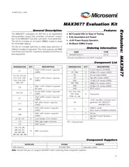
The EV kit includes an onboard 25MHz crystal to allow for immediate testing The EV kit includes switches to allow easy selection of different modes of operation The clock outputs use SMA connectors and are ACcoupled to simplify connection to test eq ID: 85048

The kit includes

Share:

Link:

Embed:

Download Presentation from below link

Download Pdf The PPT/PDF document "MAX Evaluation Kit Evaluates MAX General..." is the property of its rightful owner. Permission is granted to download and print the materials on this web site for personal, non-commercial use only, and to display it on your personal computer provided you do not modify the materials and that you retain all copyright notices contained in the materials. By downloading content from our website, you accept the terms of this agreement.


Presentation Transcript

Microsemi Corporate Headquarters One Enterprise, Aliso ViejoCA 92656 USAWithin the USA: +1 (949) 3806100Sales: +1 (949) 3806136Fax+1 (949) 2154996 Microsemi Corporation (NASDAQ: MSCC) offers a comprehensive portfolio of semiconductor solutions for: aerospace, defense and security; enterprise and communications; and industrial and alternative energy markets. Products include highperformance, high reliability analog and RF devices, mixed signal and RF integrated circuits, customizable SoCs, FPGAs, and complete subsystems. Microsemi is headquartered in Aliso Viejo, Calif. Learn more at www.microsemi.com . © 2012 Microsemi Corporation. All rights reserved. Microsemi and the Microsemi logo are trademarks of MicrosemiCorporation. All other trademarks and service marks are the property of their respective owners MAX3677 Evaluation KitEvaluates: MAX3677 7 Figure 5. MAX3677 EV Kit PCB Layout—Power Plane MAX3677 Evaluation KitEvaluates: MAX3677Figure 6. MAX3677 EV Kit PCB Layout—Solder Side MAX3677 Evaluation KitEvaluates: MAX3677 6 Figure 4. MAX3677 EV Kit PCB Layout—Ground Plane MAX3677 Evaluation KitEvaluates: MAX3677 5 Figure 3. MAX3677 EV Kit PCB Layout—Component Side MAX3677 Evaluation KitEvaluates: MAX3677 4 Figure 2. MAX3677 EV Kit Component Placement Guide—Component Side MAX3677 Evaluation KitEvaluates: MAX3677 3 Figure 1. MAX3677 EV Kit Schematic MAX3677 Evaluation KitEvaluates: MAX3677 2 Quick StartFor evaluation of the MAX3677, configure the EV kit as 1) which output is going to be evaluated and connect to the test equipment through SMA cables. Be sure not to leave any outputs unterminated, i.e., place 50 terminators on all unused outputs.2) Set high so that the on-board crystal is used. 3) a shunt on J8 (VDD_DIFF) and J10 (VDD_SE) to connect the power supply for the differential and single ended outputs. 4) a +3.3V power supply to J48 (VCC) and J2 (GND). Set the current limit to 200mA. Adjustment and Control Descriptions (see Quick Start first) INDUCTOR SHUNTJ4 shunts the power-supply inductor. Normal operation is J4 not shunted. Connects the power supply for the Q0, Q1, Q2, Q3, Q4, Q5, and Q6 clock outputs to the VCC supply.Connects the power supply for the Q7 clock output to the VCC supply. When set to HIGH, the Q4, Q5, and Q6 outputs are enabled. When set to LOW, the Q4, Q5, and Q6 outputs are disabled.When set to HIGH, the PLL locks to the crystal interface (25MHz at X_IN and X_OUT). When set to OPEN, the PLL locks to the OSC_IN input (25MHz typical). When set LOW, the PLL is bypassed and the OSC_IN input is selected. When bypass mode is selected, the VCO/PLL is disabled to save power and eliminate intermodulation spurs. 1 MAX3677 Evaluation KitEvaluates: MAX3677 General DescriptionThe MAX3677 evaluation kit (EV kit) is an assembled demonstration board that provides convenient evaluation of the MAX3677 low-jitter, precision clock generator. The EV kit includes an on-board 25MHz crystal to allow for immediate testing.The EV kit includes switches to allow easy selection of different modes of operation. The clock outputs use SMA connectors and are AC-coupled to simplify connection to test equipment. S AC-Coupled I/Os for Ease of Testing S Fully Assembled and Tested S +3.3V Power-Supply Operation S On-Board 25MHz Crystal Ordering Information Component List19-5065; Rev 0; 12/09Denotes lead(Pb)-free and RoHS compliant.EP = Exposed pad. Component Suppliers Indicate that you are using the MAX3677 when contacting these component suppliers. PARTTYPEMAX3677EVKIT+EV Kit 10% ceramic capacitor C2, C4, C5, C9, C11–C15, C20, C44, C54–C64, C66, C6710% ceramic capacitor 10% Tantalum capacitor (B case)C6, C215% ceramic capacitor 20% ceramic capacitor 5% ceramic capacitor 5% ceramic capacitor 5% ceramic capacitor J4, J8, J102-pin header, 0.1in centersSMA right-angle connectorSPDT switchJ15, J16, J35, J36, J44, J51, J52, J55, J56, J59–J62, J65, J66SMA connectors H inductor (DS1608)R1, R891% resistor (0402)Do not install (0402)5% resistor (0402)1% resistor (0402)R87, R901% resistor (0402)1% resistor (0402)SP3T switch TP1, TP2, TP3, TP5, TP26, TP28, J2, J48Test points +3.3V, low-jitter, precision clock generator (32 TQFN-EP*)Maxim MAX3677CTJ+25MHz crystalNDK America EXS00A-AT00429MAX3677 EVKIT BOARD + REV A SUPPLIERPHONEWEBSITENDK America815-544-7900www.ndk.com/en ‚ƒ„…† ‡ˆ†…ƒ†‰‚