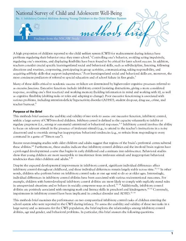
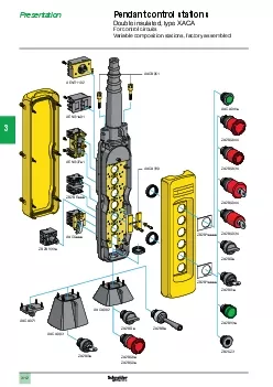
/
Product Data TYPICAL WIRING DIAGRAMS For Push Button Control Stations BULLETIN S STANDARD Product Data TYPICAL WIRING DIAGRAMS For Push Button Control Stations BULLETIN S STANDARD

Product Data TYPICAL WIRING DIAGRAMS For Push Button Control Stations BULLETIN S STANDARD - PDF document

tawny-fly
tawny-fly . @tawny-fly
Follow
688 views
Uploaded On 2014-12-19

Product Data TYPICAL WIRING DIAGRAMS For Push Button Control Stations BULLETIN S STANDARD - PPT Presentation

Assembled control stations are available in variety of combinations that can include push buttons selector switches pilot lights and special purpose devices Publication 80020 June 1989 Supersedes Publication 80020 Dated November 1977 brPage 2br Typi ID: 26580

Assembled control stations are

Share:

Link:

Embed:

Download Presentation from below link

Download Pdf The PPT/PDF document "Product Data TYPICAL WIRING DIAGRAMS For..." is the property of its rightful owner. Permission is granted to download and print the materials on this web site for personal, non-commercial use only, and to display it on your personal computer provided you do not modify the materials and that you retain all copyright notices contained in the materials. By downloading content from our website, you accept the terms of this agreement.


Presentation Transcript

800Sruggedcircuits 2Typical Wiring DiagramsFor Push Button Control StationsTable of ContentsGENERAL INFORMATION ....................... Page 2PUSH BUTTON CONTACT SELECTION ............... Page 3PILOT LIGHT SELECTION ........................ Page 4UNDERVOLTAGE PROTECTION ................... Page 4UNDERVOLTAGE RELEASE ...................... Page 4EXPLANATION OF SYMBOLS ..................... Page 5START-STOP CONTROL WIRING DIAGRAMSSingle Station - Basic Circuit ....................... Page 6With Motor Running Pilot Light ..................... Page 6With Motor Stopped Pilot Light ...................... Page 7Group of Single Stations with Master Stop Button ........... Page 7Maintained Contact Buttons- Undervoltage Release ......... Page 8Multi-StationWith Momentary Contact Push Buttons ................. Page 8REVERSING CONTROL WIRING DIAGRAMSReversing Station - Basic Circuit . . . . . . . . . . . . . . . . . . . . Page 9With Direction Indicating Pilot Lights . . . . . . . . . . . . . . . . . Page 9TWO-SPEED CONTROL WIRING DIAGRAMSTwo Speed Station - Basic Circuit . . . . . . . . . . . . . . . . . . . . Page 10With Speed Indicating Pilot Lights . . . . . . . . . . . . . . . . . . . Page 10MISCELLANEOUS WIRING DIAGRAMSSeparate Start, Stop and Jog ButtonsWith Standard Push Buttons and a Jog Relay . . . . . . . . . . . . . Page 11Thermostat Controlled MotorWith Selector Switch InfoINFORMrma Information Information tinued) *The control station wiring diagram is a representation ofthe physical station, showing the relative positions ofunits, the suggested internal wiring, and connectionsSymbols common to most circuits are explained on Page 5.NOTE The symbols used in this publication were adaptedNOTE by Allen-Bradley for use in accordance with NEMAby Allen-Bradley for use in accordance with NEMAstandards. A particular application must satisfy the needsstandards. A particular application must satisfy the needsof the user and comply with applicable codes and laws beforeof the user and comply with applicable codes and laws beforeusing any of the typical circuits shown in this publication.using any of the typical circuits shown in this publication.,,PushContact Selection"power"power circuit”. Selection lamp.terms of Allen-Bradley, Milwaukee, WI."three"two 4Typically, these circuits involve automatic pilot devices Typical Wiring DiagramsFor Push Button Control Stations5Explanation ofSymbolsMomentary Contact Push Button -Auxiliary Contacts-Operate whenOperating Coil of Contactor:Depressing button opens andparent switch does. In this case,M S - Slowcloses lower contacts. Releasing normally open (N.O.) contacts close F - ForwardF - Fastbutton returns contacts to theand normally closed (NC.) contactsR - ReverseCR-Control Relaynormal condition shown.open when coil (M) is energized. I \I 0’I 0\ 0\J 0J 0Overload Relay Contacts -a0 \J 0(One or more depending 0on starter construction). / 0 0 0.\J 0 \J 0 0)) \ 0 #)I Ll 1, I/sTtP-,2START -t3 fI ,/’ CONTROL CIRCUIT /PUSH BUTTON CIRCUITWIRING DIAGRAM 0- 0 4Reference Point-Identified onstarter, corresponds with /- 0Junction of Conductors -Absence of node indicates wiresPower Line - Symbolized byweighted lines. -BASIC r --------- 1 kla, I ! I zl I I I I I I I I fo 0; 1 --------- JSTART2STOP1 maintains IType of StationICatalog NumberrStandard Duty 800S-2SA IUNDERVOLTACE PROTECTION - If a power failure de-energizes thecircuit, hold-in contacts open. This protects against the motor startingto follow incorporate Undervoltage Protection. 800H2HA4RL Oiltight/Watertight800T-2TA --w-----v1PILOT LIGHTSTARTSTOP‘1START a.‘2‘2 U.L.1STOPI 1% lb0 0M 4)N.O.Aux.PILOT LIGHT21 IIL--------- basicII - BootedHeavy Duty Oiltight/Corrosion-ResistantCorrosion-ResistantCatalog NumberCatalog Number120V480V,60Hz600V,60Hz800S=2SAP800S-2SAP800H-2HAR800H-2HAP800H-2HAY800H-2HAV800H-2HAP2R800H-2HAY4R800H-2HAV4R800H-2HAR4RL800H-2HAP4RL800H-2HAY4RL800H-2HAV4RL800T-2TAR800T-2TAP800T-2TAY800T-2TAV Start-StopControl-WITH -_ I1STOP2 O.L. w.. c I mN.C. Aux. ’ ‘t\ w 6 L2 120V480V60Hz600V60Hz800S-2SAP800S-2SAP800H-2HAR800H-2HAP800H-2HAY800H-2HAV - BootedHeavy Duty Oiltight/Corrosion-ResistantCorrosion-ResistantCatalog NumberCatalog Number800H-2HAR4R800H-2HAR4RL800T-2TAR800H-2HAP4R800H-2HAP4RL800T-2TAP800H-2HAY4R800H-2HAY4RL800T-2TAY800H-2HAV4R800H-2HAV4RL800T-2TAVL1O.L. 0 I-Ml0 00 0-O-G --O ykMlI ;STOPAux. lo 01START L --------- O.L. ol-I 1-h 0 /STARTI0 0M2 II \Aux. 1 STOP IO 0; 12 i.,-v-w----J r”--------1 I-0 IO-I I 0I1 L 0 I--------- 800H-2HA4RL II II IA momentary contact MASTER STOP button is connected in series with a group of parallel connected circuits. Depressing thebutton de-energizes all of the circuits. 6. They could be any of the preceding or following circuits thatprovide undervoltage protection. Two wire control or undervoltage release circuits are not applicable because they would beIS released. 8Typical Wiring DiagramsFor Push Button Control StationsStart-Stop ControlWiring Diagrams 4SINGLE STATION O.L. i-c-[STARTII 1I1II lr\ 0I / ; : $77IIIII ; STOP ! L-m,----e- Oiltight/WatertightCorrosion-ResistantCorrosion-Resistant 800S-2SBM800H-2HAM800H-2HAM4R800H-2HAM4RL800T-2TAM \MULTI-STATION-WITH MOMENTARY CONTACT PUSH BUTTONSL1START1STOPSTOP oln +-o 0 00 0 0 IQAux.Operation-The motor can be started or stopped from a number of separate stations by connecting the !ISTART buttons in parallel and the STOP buttons in series. Operation of each station is the same as theI lbbasic unit on Page 6. I 1 o- &TOPPilot Lights- It is possible to add motor running, stopped, or push-to-test pilot lights to any or all of the I 0 0I Istations by connecting the lights to the circuit as shown in the diagrams below. Catalog numbers of the L---------Jrequired push button stations are listed in the appropriate pilot light circuits on Pages 6 and 7.L2L1L2L1 3L2M B4 r---v O-0 1 BAux.I B Oiltight/WatertightCorrosion-ResistantCorrosion-Resistant 1 800S-2SA800H-2HA800H-2HA4R800H-2HA4RL800T-2TA -BASICO.L. I 3 .IRI n\I IISTOP -0 I0 0R Aux.I4’ ~I II3: II2 ’I *; pj1 :IFOR.STOP IO 0; L--------- .IOperation Oiltight/WatertightCorrosion-ResistantCorrosion-Resistant 800S-3SA800H-3HA800H-3HA4R800H-3HA4RL800T-3TAL1O.L. -8,~\I IAux.IOperation is the same as the basic circuit, except that separate lights indicate in which ; REV. ; PL.I I, FOR. ; PL.II 4ain-I I I 0 i FOR.I3 ;I2 : o I 9;; h REV.I :-o0 i5 iII1 i OlQ+ I STOP ! lo 0 I 120V480V,60Hz600V,Oiltight/WatertightCorrosion-ResistantCorrosion-Resistant800H-3HA2R800H-3HA2R4R800H-3HA2R4RL800T-3TA2R800H-3HA2P800H-3HA2P4R800H-3HA2P4RL800T-3TA2P800H-3HA2Y800H-3HA2Y4R800H-3HA2Y4RL800T-3TA2Y800H-3HA2V800H-3HA2V4R800H-3HA2V4RL800T-3TA2VA2V 10Typical Wiring DiagramsTwo-Speed ControlWiring DiagramsTWO-SPEED STATION FAST - 5 B0 0I IF Aux.r---------lOperation 1. IW0 0SLOW O.L. L1: : t ;L2 1I.i4-I-I I!~~~I IO 0Operation is the same as the basic circuit, except that separate lights indicate the motor speed. 120V480V600VOiltight/Watertight800H-3HF2R800H-3HF2R4R800H-3HF2R4RL800T-3TF2R800H-3HF2P800H-3HF2P4R800H-3HF2P4RL800T-3TF2P800H-3HF2Y800H-3HF2Y4R800H-3HF2Y4RL800T-3TF2Y800H-3HF2V800H-3HF2V4R800H-3HF2V4RL800T-TF2V lSLOW ; PL.I ! I FAST ; PC.I i FAST I : lSLOWII ! ; STOP II SEPARATE START, STOP, & JOG-WITH r---------0 IO 1 0 0CR3 f1STOP 4 CRM 010-q At-14 1-1 24-oIJOG0 0Aux.I f1 :010-q 1 I tJOGI 0 0 STOP iII L--------- J0OPERATION CoilOiltight/WatertightCorrosion-ResistantCorrosion-Resistant800H-3HG800H-3HG4R800H-3HG4RL800T-3TG-WITH t4fg~;@CIRCUIT OPERATIONKnob to AutoHand&Auto z kSelector Switch to Auto-When the temperature is below thepreset value, the thermostat contacts are closed and contactorM is held in. Above this temperature, the contactsOffincluded to open the circuit if the thermostat contacts shouldKnob to HandHand Auto Oiltight/WatertightCorrosion-ResistantCorrosion-Resistant800S-R3SX800H-R3HA800H-R3HA4R800H-R3HA4RL800T-RT3A L1PL1 is shortcircuitedPL1brightly. Similarly, when PL1Push-to-Test Pilot Lights-the lights L1L2. IType ofICatalogStationNumberALLEN-BRADLEYAllen-Bradley has been helping its customers improve productivity and quality for 90 years.A ROCKWELL INTERNATIONAL COMPANYA-B designs, manufactures and supports a broad range of control and automation productsworld’s leading technology companies.With major offices worldwide.Algeria l Argentina l Australia l Austria l Bahrain l Belgium l Brazil l Bulgaria l Canada l Chile l China, PRC l Colombia l Costa Rica l Croatia l Cyprus l Czech Republic lDenmark l Ecuador l Egypt l El Salvador l Finland l France l Germany l Greece l Guatemala l Honduras l Hong Kong l Hungary l Iceland l India l Indonesia l Israel l Italy JamaicaThe Netherlands * Turkey l United Arab Emirates l United Kingdom l United States l Uruguay l Venezuela l YugoslaviaWorld Headquarters, Allen-Bradley, 1201 South Second Street, Milwaukee, WI 53204 USA, Tel: (1) 414 382-2000 Fax: (1) 414 382-4444