/
Solid Bodies and Disjointed bodies Generally speaking when modelling i Solid Bodies and Disjointed bodies Generally speaking when modelling i

Solid Bodies and Disjointed bodies Generally speaking when modelling i - PDF document

tawny-fly
tawny-fly . @tawny-fly
Follow
444 views
Uploaded On 2016-03-15

Solid Bodies and Disjointed bodies Generally speaking when modelling i - PPT Presentation

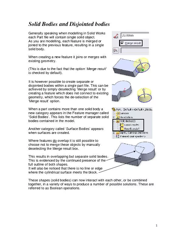
When creating a new feature it joins or merges with existing geometry This is due to the fact that the option ID: 256601

   When creating new feature

Share:

Link:

Embed:

Download Presentation from below link

Download Pdf The PPT/PDF document "Solid Bodies and Disjointed bodies Gener..." is the property of its rightful owner. Permission is granted to download and print the materials on this web site for personal, non-commercial use only, and to display it on your personal computer provided you do not modify the materials and that you retain all copyright notices contained in the materials. By downloading content from our website, you accept the terms of this agreement.


Presentation Transcript

   Solid Bodies and Disjointed bodies Generally speaking when modelling in Solid Works each Part file will contain single solid object. As you are modelling, each feature is merged or joined to the previous feature, resulting in a single solid body. When creating a new feature it joins or merges with existing geometry. (This is due to the fact that the option ‘Merge result’is checked by default). It is however possible to create separate or disjointed bodies within a single part file. This can be achieved by simply deselecting ‘Merge result’ or by creating a feature which does not connect to existing geometry , which forces the de-selection of the ‘Merge result’ option. When a part contains more than one solid body a new category appears in the Feature manager called ‘Solid Bodies’. This lists the number of separate solid bodies contained in the model. Another category called ‘Surface Bodies’ appears when surfaces are created. Where features do overlap it is still possible to choose not to merge these objects by manually deselecting the Merge result box. This results in overlapping but separate solid bodies. This is evidenced by the continued presence of the full outline of both shapes. It will also be noticed that there is no line or edge where the cylindrical surface meets the block. These shapes (solid bodies) can now interact with each other, or be combined together, in a variety of ways to produce a number of possible solutions. These are referred to as Boolean operations.    Boolean operationsWhere solid bodies overlap but are not merged it is possible to combine them in a variety of ways. The concept resembles that of a mathematical topic called Venn diagrams or Set Theory, in which overlapping regions could be combined in a variety of ways. These include Union (add) Subtraction (subtract) Intersection (common) Add enables the creation of a new body by joining or ‘unioning’ two separate bodies. Subtract enables the creation of a new body by subtracting the portion where the second feature overlaps the primary feature or main body. Common (intersect) enables a new body to be created from the overlapping portion.    Moving / Re-Sizing Solid Bodies Individual solid bodies can be moved / resized independently within the part environment. Dynamic editing is made possible using the option. With dynamic editing activated; on selecting the solid body shown, a number of arrows or ‘handles’ appear. Selecting the red or dark green arrows allow the object to be dragged in the X or Y directions. Selecting the light green or radial arrow allows the diameter to be adjusted. Finally selecting the blue dot at the top of the top of the height dimension allows the height to be adjusted. Selecting any of these handles causes an interactive ruler to appear. This method of adjustment is only suitable for concept development or movements where accuracy is not important. More precise movement is available using:- Insert Features Move/Copy In the dialog box which appears select the option. On selecting the object, 3 coloured arrow and 3 coloured rings appear. The object may now be moved (or translated) in X, Y or Z directions by selecting and dragging the red, green or blue arrow. Alternately it may be rotated about the X, Y or Z axis by selecting and dragging one of the red, green or blue rings. The solid body can also be moved (translated or rotated) by a precise amount, by entering values in the appropriate edit boxes in the Property Manager pane.    Tutorial: Basic Mould In the following exercise we will create a cavity within a block for moulding a plastic cup. Rather than using dedicated mould creation tools, this exercise will use native SolidWorks commands to achieve the desired effect. First of all create a part in solid works called ‘Basic-Mould.sldprt’. Modelling the component. Start by creating an inverted cup shaped component on the top plane. Specify a diameter of 50mm, a height of 60mm and a taper angle of degrees. Next hollow out the component from below specifying a wall thickness of 3mm using the Shell command. At this point save the part as ‘Product.sldprt’ using the Save as copy option. This allows the part to be saved with another name without affecting the name of the existing model. Next create a parallel plane 100mm below the existing top plane and then create a sketch on the plane with a rectangle 80mm x 80mm centred on the product model. Then extruding in two directions, extrude upward by 90mm and downwards by 30mm. You model should now look as shown opposite.    Using the move/copy command move this block up around the cup. On selecting the move copy command select the Translate rotate option. Move upwards by 100mm. Trial and error may be need to find the correct direction. N.B. It is not technically necessary, to model the mould block below the part model and to move it into place. However it does trigger the Merge result to turn off automatically and also demonstrates the Move/Copy solid bodies tool. Creating the cavity Now use a ‘Boolean subtract’ command to create the cavity within the mould. This is achieved by selecting the Combine option followed by the Subtract option. Finally use a clipping plane to reveal and check the resulting cavity within the block.    Separating the core and cavity into separate solid bodies. We will now split the existing solid body into separate solid bodies. To do this select the top plane followed by: Insert Features Split To split the body select ‘Cut Part’. Unfortunately this creates 3 rather than 2 solid bodies.This will be rectified later. The three solid bodies created when you select the ‘Cut Part’ button, appear in the Resulting Bodies box as shown opposite. To keep these bodies select the check- box beside each and then select OK (green arrow)  Rejoining core and corebase Unfortunately, as can be seen, rather than cutting the model into two separate bodies, it cut it into three , by truncating the core from its base. To re-join the core and base, choose the combine command. Then using the Add option and select bodies A and B. This joins or unions these two bodies and removes all evidence of a cut between them.    Modifying the part “A modification of the component is required which necessitates the use of a sliding core”. Open the Product part saved earlier and make the following modification. Working on the Front plane create the sketch shown opposite, then create a cutout in one direction through the side of the component. Finally round the corners using a 1.5mm radius. The end result should look as shown opposite. Resave the part. Preparation for Side Core The part will now be re-inserted into the mouldbase to guide the modification. To do this:- Select insert Part and choose the Product.sldprt’. From the various options which appear select Solid Bodies followed by accept . This will cause the component to be inserted at the origin. You should now see the component sandwiched between the core and cavity, with the rectangular hole.Next we will model a side core needed to mould this part.   Cutting recess for side core Switching to wireframe, select the face of the cavity block at the side corresponding to the side of the hole feature in the component. Create a rectangle 20 x 18 centred on the origin and with it bottom edge coincident with the top plane or split line. Finally cut a hole through the side of the cavity block using the Up to Next option. This will cause Solid Works to cut until it encounters the next surface or interface. i.e. the inside surface of the cavity block. This will cause it to cut the cavity block while having no affect on either the component or core block. We will now create another ‘Solid Body’ feature to represent the side. This will be done by creating a sketch on the same plane and converting the edges of the existing opening. The resulting sketch will then be extruded but not merged resulting in a separate solid body feature. It is not possible to extrude up to multiple solid bodies at the same time. Therefore we will extrude up to the core and then subtract the part model, to leave the desired impression on the side core. The resulting sliding core should look as shown opposite.