/
STUDY ON DEVELOPMENT AND PRACTICAL USE OF RUMBLE STRIPS AS A NEW MEASU STUDY ON DEVELOPMENT AND PRACTICAL USE OF RUMBLE STRIPS AS A NEW MEASU

STUDY ON DEVELOPMENT AND PRACTICAL USE OF RUMBLE STRIPS AS A NEW MEASU - PDF document

tawny-fly
tawny-fly . @tawny-fly
Follow
399 views
Uploaded On 2016-07-26

STUDY ON DEVELOPMENT AND PRACTICAL USE OF RUMBLE STRIPS AS A NEW MEASU - PPT Presentation

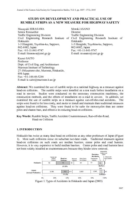
Journal of the Eastern Asia Society for Transportation Studies Vol 6 pp 3697 3712 2005 3 DEVELOPMENT OF INSTALLATION METHODS IN JAPAN machine for installing such strips Many methods for cont ID: 420308

Journal the Eastern Asia

Share:

Link:

Embed:

Download Presentation from below link

Download Pdf The PPT/PDF document "STUDY ON DEVELOPMENT AND PRACTICAL USE O..." is the property of its rightful owner. Permission is granted to download and print the materials on this web site for personal, non-commercial use only, and to display it on your personal computer provided you do not modify the materials and that you retain all copyright notices contained in the materials. By downloading content from our website, you accept the terms of this agreement.


Presentation Transcript

STUDY ON DEVELOPMENT AND PRACTICAL USE OF RUMBLE STRIPS AS A NEW MEASURE FOR HIGHWAY SAFETY Masayuki HIRASAWA Traffic Engineering Division Civil Engineering Research Institute of 1-3 Hiragishi, Toyohira-ku, Sapporo, Fax: +81-11-841-9747 E-mail: hirasawa@ceri.go.jp Director Traffic Engineering Division Journal of the Eastern Asia Society for Transportation Studies, Vol. 6, pp. 3697 - 3712, 2005 3. DEVELOPMENT OF INSTALLATION METHODS IN JAPAN machine for installing such strips. Many methods for continuously installing milled grooves were examined, to clarify the installation effectiveness and economic efficiency. We modified an existing machine by equipping it translates rotational movement into up-down movement as the vehicle moves ahead (Figures 3 and 4; Table 2). Bits on the milling drum are removable, which enables adjustment of thto the roadway direction) at intervals of 6 mm in the range between 15 cm and 35 cm. The groove depth is also easily adjustable. The milling rate of approximately 3 m per minute enables about 800 m of installation in a day. The low installation cost (about 1,500 yen/m) owes to 1) the low initial cost of machine development (simple modification of a commercially available machine) and 2) the low labor The installation cost ispoles and one-third that for raised markers. 4. MEASUREMENT OF SOUND AND VIBRATION ON THE TEST TRACK The greater the groove dimensions, the greater the warning. The smaller the groove dimensions, the less the disrupticle riders. It was necessary to set optimum groove dimensions to satisfysmaller than the width of the yellow double centerline (50 cm). We installed three 100-m-long rumble strips of different dimensions and depths on sections of the Tomakomai Winter Test Track. The standard depths were set as 9 mm, 12 mm, and 15 mm. The longitudinal groove withe roadway) and the length of the flat intervals between grooves were determined according to the diameter of the milling drum, the non-circular profile of the guide wheel, and the groove depth (Table 3 and Figure 5). We measured sound and vibration for evaluation of three depths. The sound and vibration generated by the rumble strips were measured using a noise meter (RION NL-22) and a vibration meter (RION VM-82) installed as in Figure 6. The test vehicle was driven on the rumble strips of three dimensions. The measurement vehicle was The test vehicle drove at 40 km/h, 60 km/h, 80 km/h and 100 km/h three times for each speed on each test section. The sound and Figure 3. Milling by a Vehicle That Employs a Wheel of Non-Circular Profile The NonThe Noncircular Guide Wheelcircular Guide WheelThe Milling The Milling DrumDrum The NonThe Noncircular Guide Wheelcircular Guide WheelThe Milling The Milling DrumDrum g Table 2. Specifications ManufacturerWirt g en GmbH ( German y) Mode l W350Drivin g method3-wheelDimensionsL=2.79mW=1.15mH=1.87mWei g ht4.10Power32kwMillin g drum dimensionsW=350mm =460mmNumber of millin g bits118 vibration values are the average of the three test runs (Figures 7 and 8). The sound generated by rumble strips of all three depths was 15 dB greater than the sound on pavement without warning facilities. The deeper the groove, the louder the sound. Chen ease of 4 dB. We can expect rumble strips provide sufficient warning. The vibration measured on the rumble strips of each depth exceeded that on smooth pavement by 7 dB. The smallest vibration was measured at the driving speed of 60 km/h, which we suspension performance. At each test speed other than 60 km/h, the measured vibration for each groove depth exceeded that generated on the smooth pavement by 10 dB. Table 3. Dimensions of Rumble Strips Installed at the Test Track Pattern 1Pattern 2Pattern 3Transverse width a350350350Len g thwise width b127147163 p acin g c175155139 p th d91215Unit: mm Figure 5. Rumble Strips (12 mm depth) (left) and Vibration (right) 60.065.070.075.080.085.090.095.040km/h60km/h80km/h100km/hDriving speedSound (dB ) no strips 9mm 12mm 15mm 90.095.0100.0105.0110.0115.0120.040km/h60km/h80km/h100km/hDriving speedVibration (dB ) no strips 9mm 12mm 15mmFigure 8. Vibration vs. Speed 5. EXPERIMENT ON THE TEST TRACK Our experiments were conducted at Tomakomai Winter Test Track in November 2001 (Figure 9), with 62 road users participating. The vehicle driven by the participant was videotaped rumble strips. The vehicles used were passenger cars, motorcycles, small (50 cc) motorcycles, and bicycles. Each participant traveled three times on each test section, each time in a different type of vehicle. After the driving/riding experiment, each participant filled out the questionnaire. Some participants on their first section installed with rumble strips; however, no dangerous situations were second or third run. Some bicycle riders wnot brake suddenly, turn suddenltypes of rumble strip. We stalled with rumble strips at the centerline. questionnaire on safety. The participants’ negative evaluation of the rumble strips incrshallow grooves. Based on our measurements of sound and viquestionnaire survey, we concluded that grooves with a lateral width of 150 mm, transverse width of 350 mm, and depth of 12 mm are optimum (Figure 11). 6. EFFECT OF RUMBLE STRIPS ON ROADS IN SERVICE le Strips on National Route 5 Japan’s first milled rumble strips were installed as a countermeasure to head-on collisions on the Yakumo Town section of National Route 5 two-lane road in the suburbs of the town. The road structure and environment were not Figure 9. Driving Test: Small (50 cc) Motorcycle (left) and Bicycle (right) 0%20%40%60%80%100%15 mm12 mm9 mmDepth of rumble strips Felt safe Felt somewhat dangerous Felt dangerousFigure 10. Subjective Ratings of Safety 12 mm deep Cross section of the pavement 12 mm deep Cross section of the pavement Figure 11. Dimensions of Rumble Strips Installed on Roads in Service ed Grooves of Rumble Strips (right) on the Yakumo Section of National Route 5 Median stripCenter polesChatter barsRumble stripsYellow doublecenterline1.0km0.8km0.8km0.7km1.0km For Hakodate For Sapporo Figure 13. Installation of Measures against Head-on Collision on the Yakumo Section of there had been many head-on collisions. A median strip, center poles, and chatter bars were installed in one section for the test. We evaluated how rumble strips influenced drivithe section and the installed facilities. Evaluation was conducted using video cameras transverse location ofDriving speed was calculated using the times recorded in the frames in which the vehicle was captured entering and exiting the measurement section. The differences in average driving speed of southbound vehicles measured in each section were within 2 km/h (Table 4). It is assumed that safety measures including rumble strips do not affect driving speed of the Table 4. Average Driving Speed Observed for 2 h (Unit: km/h) Hakodate-bound laneMedianstripsectionCenter polesectionChatter barsectionRumblestripsectionYellow doublecenterlinesection67.567.868.068.268.8(589)(587)(593)(592)(570)66.067.367.167.067.4(200)(197)(199)(198)(193)Note: Numerals in parentheses are numbers of vehicles.Small carsLargevehicles Many respondents expressed a wish that road managers not install center poles or chatter bars, but they did call for those facilities to be employed to head-on collision. the two facilities were effective against head-on collisions. The many negative answers regarding the two facilities may be attributablefacilities (Figure 16). 6.3 Sound and Vibration on Winter Roads rumble strips were empirically confirmed on snow-covered roads. We measured the sound meter (RION NL-22) and a multipurpose vibration meter (RION VM-82) mounted in a test vehicle. The measurement method is the same as in Section 4. Figure 18 shows the road surface condition of Natime of measurement and the sound and vibration measured inside the test vehicle. The road surface was slushy, and the centerline was not visible. Without was 60 to 65 dB; with rumble strips it was 75 to 80 dB. Vibration was 90 to 95 dB when not running on rumble ps. It was confirmed sufficient warning (sound and vibration) of laneer roads, even when the centerline was invisible. Sound and vibration on winter roads were measured for 10 days. Warning on compacted-snow road surface and slushy road surface was sufficient. The warning given by rumble strips on national maintenance level is sufficiently reliable in winter. 7. DEVELOPMENT OF A STANDARD FOR RUMBLE STRIPS AT A YELLOW SINGLE CENTERLINE AND AT THE SHOULDER The length of rumble strips installed against head-on collisioto 89.5 km in September 2004. The Hokkaido Regional Development Bureau has a policy of inst 10011012009:50:5209:50:5709:51:0209:51:0709:51:1209:51:1709:51:2209:51:2709:51:3209:51:3709:51:4209:51:47 Passing over the rumble strip Sound Vibration (dB ) (Sapporo-bound)Driving speed: 60 km/h, Weather: Snowy,Road surface condition: Slushy, Awareness of rumble strips: GoodFigure 18. Sound and Vibration Measured on a Winter Road (R274, Jan. 20, 2004) (Left: Road Surface Conditions, Right: Sound and Vibration Measurements) (see Figure 2). To promote their further use, we conducted examinations to determine standards for 150-mm-wide rumble strips (hereinafter, slim rumble strie centerline. We installed grooves of three different depths (9 mm, 12 mm, and 15 mm) at Tomakomai Winter Test Track for a driving test. We also examined standardizing shoulder rumble strips as a measure against run-off-the-road accidents. Their installation on national highways would require that they not disrupt small (50 cc) motorcycles and bicycles. The examined shoulder strips are narrower in lateral width and shallower than the standard e centerlines (see Figure 11). Based on our examination, we set the lateral width, transvmm. We chose 115 mm (short-interval stripsinterval between the two grooves. We conducted driving experiments to compare the two types of shoulder strip at Tomakomai Winter Test Track. For comparison, our driving experiment on rumble double centerlines with 12-mm-deep grooves (center rumble strips), high-visibility carriageway markings, and chatter bars (Figure 19). We developed a machine for milling shoulder strips, because the lateral width for such strips is 80 mm and a milling drum with a small outer diameter of 180 mm is required (Figure 20). 130㩷㩷㩷㩷170㩷㩷㩷㩷130 150㩷㩷㩷㩷150㩷㩷㩷㩷150 㩷130㩷㩷㩷170㩷㩷㩷130 150 350 80㩷115㩷80 80㩷150㩷80 170 131 Slim strip (9 mm deep)Slim strip (12 mm deep)Slim strip (15 mm deep)Shoulder strip (shortinterval, 9 mm deep)Shoulder strip (longinterval, 9 mm deep)High-visibility carriagewaymarking (height of raised p art: 4 to 5.5 mm ) Chatter bar (36mm high)Figure 19. Dimensions of Slim and Shoulder Rumble Strips (mm) r Shoulder Rumble Strips (Left: Machine, Right: Milling Drum) Head-on collisions before installation numbered 42 at 24 locations, and after installation numbered 15. To compare the accident rate of before and after, the figure for after needed to . The accident reduction rate was calculated to be 55.2%. 8.3 Effectiveness of the Rumble Strips The advantages of the rumble strips are these: A high degree of warning is given to drivers who deviate to the edge of the road. Two-wheel vehicles can travel more safely on sections with rumble strips than on those with center poles Rumble strips do not hinder snow removal. The costs are low (half of that for center polat for chatter bars). Because the rumble strips are not installed where the wheels of vehicles pass, they cause do not affect the traveling speed. The warning given by sound and vibration was confirmed on road surfaces whose carriageway markings were covered by compacted snow. The snow accumulated in the groove was removed by using anti-freezing agent. No disadvantages in winter road maintenance are expected. Currently, center rumble strips reduce head-on collisions by 55%. The installation cost is moderate, and high cost-effectiveness can be achieved. High effectiveness can be expected in using center rumble strips against head-on collisions. Unlike median strips, center poles, and chatter bars, rumble strips do not hinder snow removal. They can be highly effective against head-on collisions in cold, snowy regions like Hokkaido. Currently, the Hokkaido Regional Development Burrumble strips might be a factor in accidents caused by loss of control of two-wheel vehicles. The Bureau has limited them to no-passing zones. On road sections where head-on collision mitigation requires physical structures, median strips have been constructed. On ideal to take measures that satisfy the requirements of effectiveness within the constraints of the road environment. The standards presently employed for shoulder strips have improved safety for small rs. Shoulder strips can be effectively employed on the road sectmany run-off-the-road accidents and on approaches to narrow bridges ae to serious accidents such vehicle-structure crashes. 8.4 Promotion of the Facility To promote wider use of rumble strips, it isdepartments and to provide technical informaof the road management authority. We have opportunities to exchange opinions with the traffic control authority at the Hokkaido Traffic Accident Examination Council. We are providing them with information on rumble strips, including experiment results and recommended standards. For facilitate the provision of information to road maintenance site managers, the Civil Engineering Research Institute of Hokkaido has held technical training sessions, launched a Web site (http://www2.cer.go.jp/rumble/), produced and distributed video materials on related echnology Information System Infrastructure and Transport. At our Web site, we outline rumble strips and their installation methods and effects. We esboth road managers and general road users. 9. CONCLUSION Rumble strips are an inexpensive way of mitigating head-on collisions, and they cost nothing to maintain. There are fewer constraints on their installation than for conventional measures. They are much safer for motorcyclists than are center poles and chatter bars. The facility accident reduction. In the past, even after a head-on collision or run-off-the-road accident on a certain section of a two-lane road, it was often difficult to take decisive countermeasures using conventional methods because of the constraints of cost and/or roadside environment. Rumble strips are a possible solution for such sections. Local road administrators have evaluation. We were concerned ny complaints regarding such matters. The Hokkaido Regional Development Bureau emphasizes rumble strips as a major measure against head-on collisions and is planning of rumble strips in the five years from 2004. For future study, we will assess and verify the effectiveness of rumble strips installed in no-passing zones with yellow single centerlines and at the shoulder. We will promote widespread use of rumble strips to further reduce head-on collisions. We plan to launch a Web site in English (http://www2.ceri.go.jp/rumble/eng/) in 2005. Through this site we will rumble strips and to dissemicountries where traffic accident mitigation is urgently required. REFERENCES Wood, N. E. (1994) Shoulder Rumble Strips: A Method to Alert “Drifting” Drivers, Presented at the 73 Annual Meeting of Transportation Research Board, Washington, A Study of Effectiveness of Various Shoulder Rumble Strips on Highway Safety, Virginia Department of Transportation, Richmond, Va. The Effectiveness and Use of Continuous Shoulder Rumble StripsFederal Highway Administration Albany, New York. Outcalt, W. (2001) Centerline Rumble Strips, Report No. CDOT-DTD-R-2001-8Department of Transportation, Denver, Co. Development of Traffic Accident Analysis System Using Proceedings of the 5th EASTS Conference This research aims to evaluate the effectiveness of rumble strips against head-on collisions. Rumble strips are rectangular grooves incised in the pavement (Figure 2). They warn drivers who deviate from their lane with rumbling sound and vibration rumble strip. We propose installation methods and optimum standards for rumble strips and describe their effectiveness as a measure against 2. HISTORY OF RUMBLE STRIPS IN THE UNITED STATES Rumble strips were first used in 1955, in New Jersey. Called “singing shoulders,” these d on concrete pavement. Rumble strips are categorized into four types: milled, rolled, formed and raised (Table 1). shoulder of the Pennsylvania Turnpike in 1987. Wood (1994) reported that run-off-the-road installation. Chen (1994) reported that milled strips generate 12.6 times the vibration and 3.4 times the noise of rolled strips. Many other states started to employ milled strips after the Virginia DOT introduced them. Perrillo (1998) reported that installation of 5,071 km of milled rumble strips at the shoulders of freeways in New York State from 1993 to 1998 reduced run-off-the-road accidents by 65% and that these facilities’ cost-effectiveness was 182. The high cost-effectiveness reported in some studies and the development of a milling method for installation on existing pavements promoted the spread of rumble strips in the early 1990s. The facility was quickly employed against run-off-the-road accidents on Outcalt (2001) reported on milled rumble strips installed at the centerline of a 27-km two-lane section of State Highway 119 the rumble strips reduced accidents per million vehicles by 34% for head-on collisions and 36% for sideswipe accidents. Figure 2. Rumble Strips InstTable 1. Types of Rumble Strip MilledRolle d FormedRaisedInstallationmethodPavement is groundusing a grindingmachine orcustomized machine.A raised line orbuttons areinstalled by heatadhesion.Installed…whenever necessaryat the time of roadconstruction (asphaltpavement)at the time ofconcrete casting(concretepavement)whenevernecessaryGrooves are formed using a roller ora mold placed on the road surface. vibration values are the average of the three test runs (Figures 7 and 8). The sound generated by rumble strips of all three depths was 15 dB greater than the sound on pavement without warning facilities. The deeper the groove, the louder the sound. Chen ease of 4 dB. We can expect rumble strips provide sufficient warning. The vibration measured on the rumble strips of each depth exceeded that on smooth pavement by 7 dB. The smallest vibration was measured at the driving speed of 60 km/h, which we suspension performance. At each test speed other than 60 km/h, the measured vibration for each groove depth exceeded that generated on the smooth pavement by 10 dB. Table 3. Dimensions of Rumble Strips Installed at the Test Track Pattern 1Pattern 2Pattern 3Transverse width a350350350Len g thwise width b127147163 p acin g c175155139 p th d91215Unit: mm Figure 5. Rumble Strips (12 mm depth) (left) and Vibration (right) 60.065.070.075.080.085.090.095.040km/h60km/h80km/h100km/hDriving speedSound (dB ) no strips 9mm 12mm 15mm 90.095.0100.0105.0110.0115.0120.040km/h60km/h80km/h100km/hDriving speedVibration (dB ) no strips 9mm 12mm 15mmFigure 8. Vibration vs. Speed 5. EXPERIMENT ON THE TEST TRACK Our experiments were conducted at Tomakomai Winter Test Track in November 2001 (Figure 9), with 62 road users participating. The vehicle driven by the participant was videotaped rumble strips. The vehicles used were passenger cars, motorcycles, small (50 cc) motorcycles, and bicycles. Each participant traveled three times on each test section, each time in a different type of vehicle. After the driving/riding experiment, each participant filled out the questionnaire. Some participants on their first section installed with rumble strips; however, no dangerous situations were second or third run. Some bicycle riders wnot brake suddenly, turn suddenltypes of rumble strip. We stalled with rumble strips at the centerline. questionnaire on safety. The participants’ negative evaluation of the rumble strips incrshallow grooves. Based on our measurements of sound and viquestionnaire survey, we concluded that grooves with a lateral width of 150 mm, transverse width of 350 mm, and depth of 12 mm are optimum (Figure 11). 6. EFFECT OF RUMBLE STRIPS ON ROADS IN SERVICE le Strips on National Route 5 Japan’s first milled rumble strips were installed as a countermeasure to head-on collisions on the Yakumo Town section of National Route 5 two-lane road in the suburbs of the town. The road structure and environment were not Figure 9. Driving Test: Small (50 cc) Motorcycle (left) and Bicycle (right) 0%20%40%60%80%100%15 mm12 mm9 mmDepth of rumble strips Felt safe Felt somewhat dangerous Felt dangerousFigure 10. Subjective Ratings of Safety 12 mm deep Cross section of the pavement 12 mm deep Cross section of the pavement Figure 11. Dimensions of Rumble Strips Installed on Roads in Service The transverse location in the lane (location of the left front wheel) was recorded by video camera. To clarify the transverse location of the passing vehicle, the pavement was marked in 20-cm increments in the transverse direction, at the outer edge of the shoulder. The number of vehicles that passed each mark was added up. The cameras measured traffic in both directions for one hour. Figure 14 shows the number of large vehicles that passed each mark in the countermeasure. The figures in boxes are the number of passing vehicles at each countermeasure section and the average of the distances from mark shoulder and carriageway) to the vehicle passing locations. es traveled on the shoulder. In parated the lanes, many vehicles distanced themselves from the center poles, and some even drove on the soft shoulder. In the chatter bar and rumble strip sections, the vehicles distanced themselves from these structures, but not as far as on the center pole section. Small vehicles showed the same behavior as large vehicles. The rumble strips were regarded as being effective in reducing head-on collisions because they kept vehicles at a proper distance from the centerline. 6.2 Road User Questionnaire Survey A questionnaire survey was conducted to assess the road users’ evaluation of the four types of head-on collision countermeasure installed on the experiment section of National Route 5 in Yakumo Town. Hokkaido Prefectthe experiment section. The questionnaire (Figure 15). We explained the aim of the questionnaire to each driver and asked each to cooperate in filling it out and was conducted on November 8, 2002, and 601 questionnaire forms were distributed and 229 were collected later. Respondents were asked, “What was it like to drive on the section with the median strip?” ility (“I felt comfortable driving there” or “I acility (Figure 16). To the question about the center poles, many respondents answered that th Hakodate-bound lane (large vehicles)12345678910111213Passing locationsNo. of vehicles Median strip section Center pole section Chatter bar section Rumble strip section Yellow double centerlinesection Shoulde r WhitelineCarriagewa y Average: 34.9 cmVehicles: 78 A verage: 17.3 cmVehicles: 87 Average: 57.6 cmVehicles: 84 A verage: 36.0 cmVehicles: 83 Average: 67.1 cmVehicles: 87 Center poleChatter barRumble stripYellow doublecenterlineMedian strip Figure 14. Number of Vehicles at Each Transverse Point (Hakodate-bound Lane, Large Vehicles) (see Figure 2). To promote their further use, we conducted examinations to determine standards for 150-mm-wide rumble strips (hereinafter, slim rumble strie centerline. We installed grooves of three different depths (9 mm, 12 mm, and 15 mm) at Tomakomai Winter Test Track for a driving test. We also examined standardizing shoulder rumble strips as a measure against run-off-the-road accidents. Their installation on national highways would require that they not disrupt small (50 cc) motorcycles and bicycles. The examined shoulder strips are narrower in lateral width and shallower than the standard e centerlines (see Figure 11). Based on our examination, we set the lateral width, transvmm. We chose 115 mm (short-interval stripsinterval between the two grooves. We conducted driving experiments to compare the two types of shoulder strip at Tomakomai Winter Test Track. For comparison, our driving experiment on rumble double centerlines with 12-mm-deep grooves (center rumble strips), high-visibility carriageway markings, and chatter bars (Figure 19). We developed a machine for milling shoulder strips, because the lateral width for such strips is 80 mm and a milling drum with a small outer diameter of 180 mm is required (Figure 20). 130㩷㩷㩷㩷170㩷㩷㩷㩷130 150㩷㩷㩷㩷150㩷㩷㩷㩷150 㩷130㩷㩷㩷170㩷㩷㩷130 150 350 80㩷115㩷80 80㩷150㩷80 170 131 Slim strip (9 mm deep)Slim strip (12 mm deep)Slim strip (15 mm deep)Shoulder strip (shortinterval, 9 mm deep)Shoulder strip (longinterval, 9 mm deep)High-visibility carriagewaymarking (height of raised p art: 4 to 5.5 mm ) Chatter bar (36mm high)Figure 19. Dimensions of Slim and Shoulder Rumble Strips (mm) r Shoulder Rumble Strips (Left: Machine, Right: Milling Drum) Table 5 shows the test vehicles used and the number of participants for each vehicle. A total of 106 road users participated. A passenger car, a motorcycle (400 cc), a small (50 cc) motorcycle, and a bicycle were used. The patest track experiment. The participants indicated a subjective evaluation of the effectiveness of rumble strips against head-(for motorcycle and bicycle) for each test vehicle. Evaluations were given according to a 5-point scale (Figure 23). We totaled the evaluation scores for each vehicle and divided the sum by the number of participants who used the vehicle. The results are shown in Figure 24. were rated the highest as a countermeasure to head-on collision, followed by the slim strips (15 mm deep). The long-interval shoulder given for center rumble strips. Two-wheel vehicle riders gave slim rumble strips, but bicycle riders gave low scores for safety to the slim strips with 15-mm-deep grooves. The shoulder rumble stripsbicycle riders. The safety evaluation for high-visibility carriageway marking was high among riders of large and small motorcycles and bicycles, but was low among passenger car drivers. The results for chatter bars were the opposite. Table 5. Driving Test Participants and Vehicles Used VehicleNumber of participants Passenger car105Motorcycle69Small (50 cc) motorcycle101Bicycle105Number of participants: 106 IneffectiveEffectiveDangerousSafe(Question)Please answer on a scale of 1 to 5 the effectiveness felt while driving as against head-on collision .Please answer on a scale of 1 to 5 the safety felt while driving.Figure 23. Questionnaire Answer Form (excerpt) 0.001.002.003.004.005.00Chatter barsHigh-visibility carriageway markingShoulder strip (short interval)Shoulder strip (long interval)Slim strip (15 mm)Slim strip (12 mm)Slim strip (9 mm)Center strip (12 mm) Effectivenessscores forpassenger cardrivers asagainst head-on collision Safety scoresfor motorcycleriders Safety scoresfor small (50cc)motorcycleriders Safety scoresfor bicycleriders Ineffective 㸠䇭䇭䇭䇭Effectiveness 䇭䇭䇭㸢EffectiveDangerous㸠䇭䇭䇭䇭䇭䇭䇭䇭Safety䇭䇭䇭䇭䇭䇭䇭䇭䇭䇭䇭䇭SafeAverage scores The Bureau experimentally installed five sections with slim strips (7.7 km) and six sections with shoulder strips (21.3 km) in FY 2004. The Bureau will finish evaluating these facilities at the end of FY 2004, and start practical insts in Hokkaido in FY 8.2 Head-on Collision Reduction Rate Table 6 shows the numbers of head-on colinstallation of center rumble strips at 24 locations. The number of accidents for “before” is that for the two years before installation. The number of accidents for “after” is that from the day of installation to December 31, 2004. Figure 27. Center Strips (R230) Figure 28. Slim Strips (R5) Figure 29. Shoulder strips (R238) 39.2 111.9 3.9 7.721.30.040.080.0120.0160.0200220032004Fiscal Year(km) Center strip Slim strip Shoulder strip Figure 26. Length of Rumble StripsTable 6. Number of Accidents Before and After Installation Beforeinstallation(2 years)Frominstallation toDec. 1, 2004Extrapolatedafter installation (2 years)157272002/7/2210.022742,7082002/11/6333.0354572002/12/1010.04376,1972003/5/13111.2551,5002003/5/2630.06401,1782003/6/220.072742,8602003/6/930.082745,0502003/6/16767.892743,8152003/6/23333.91051,5072003/7/1311.3112757302003/7/810.012391,1002003/7/2210.013444002003/7/2500.0142302,9432003/7/3010.01553002003/8/510.0162301,0572003/8/2620.01755222003/9/22111.6182763,4482003/9/420.01956002003/9/310.0203934402003/9/1600.02154422003/10/200.022403822003/10/2210.0232362002003/10/2710.024387212003/11/130.039,284421518.8TotalReduction rate for head-on collisions: (42-18.8)/42*100=55.2%Number of head-on collisionsRouteLengthinstalled(m)Date ofconstruction echnology Information System Infrastructure and Transport. At our Web site, we outline rumble strips and their installation methods and effects. We esboth road managers and general road users. 9. CONCLUSION Rumble strips are an inexpensive way of mitigating head-on collisions, and they cost nothing to maintain. There are fewer constraints on their installation than for conventional measures. They are much safer for motorcyclists than are center poles and chatter bars. The facility accident reduction. In the past, even after a head-on collision or run-off-the-road accident on a certain section of a two-lane road, it was often difficult to take decisive countermeasures using conventional methods because of the constraints of cost and/or roadside environment. Rumble strips are a possible solution for such sections. Local road administrators have evaluation. We were concerned ny complaints regarding such matters. The Hokkaido Regional Development Bureau emphasizes rumble strips as a major measure against head-on collisions and is planning of rumble strips in the five years from 2004. For future study, we will assess and verify the effectiveness of rumble strips installed in no-passing zones with yellow single centerlines and at the shoulder. We will promote widespread use of rumble strips to further reduce head-on collisions. We plan to launch a Web site in English (http://www2.ceri.go.jp/rumble/eng/) in 2005. Through this site we will rumble strips and to dissemicountries where traffic accident mitigation is urgently required. REFERENCES Wood, N. E. (1994) Shoulder Rumble Strips: A Method to Alert “Drifting” Drivers, Presented at the 73 Annual Meeting of Transportation Research Board, Washington, A Study of Effectiveness of Various Shoulder Rumble Strips on Highway Safety, Virginia Department of Transportation, Richmond, Va. The Effectiveness and Use of Continuous Shoulder Rumble StripsFederal Highway Administration Albany, New York. Outcalt, W. (2001) Centerline Rumble Strips, Report No. CDOT-DTD-R-2001-8Department of Transportation, Denver, Co. Development of Traffic Accident Analysis System Using Proceedings of the 5th EASTS Conference