/
Y567B PA test at 76 MHz Y567B PA test at 76 MHz

Y567B PA test at 76 MHz - PowerPoint Presentation

tawny-fly
tawny-fly . @tawny-fly
Follow
381 views
Uploaded On 2017-07-08

Y567B PA test at 76 MHz - PPT Presentation

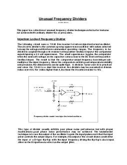
Robyn madrak Booster 2 nd Harmonic Cavity Meeting 19 Jan 2017 PA test at 76 MHz Previously had tested PA at 719 MHz anode resonator frequency To test at 76 MHz added a ring to increase the frequency and a modified jumper for the 50 ohm load connection in order to get the optimal imp ID: 568029

anode power 2017 meeting power anode meeting 2017 mhz robyn madrak booster harmonic cavity 2nd drive resonator cathode test

Share:

Link:

Embed:

Download Presentation from below link

Download Presentation The PPT/PDF document "Y567B PA test at 76 MHz" is the property of its rightful owner. Permission is granted to download and print the materials on this web site for personal, non-commercial use only, and to display it on your personal computer provided you do not modify the materials and that you retain all copyright notices contained in the materials. By downloading content from our website, you accept the terms of this agreement.


Presentation Transcript

Slide1

Y567B PA test at 76 MHz

Robyn madrak

Booster 2

nd

Harmonic Cavity Meeting

19 Jan 2017Slide2

PA test at 76 MHz

Previously, had tested PA at ~71.9 MHz (anode resonator frequency)

To test at 76 MHz, added a ring to increase the frequency, and a modified jumper for the 50 ohm load connection, in order to get the optimal impedance

1/19/2017

Robyn Madrak | Booster 2nd Harmonic Cavity Meeting

2Slide3

Original and Modified1/19/2017Robyn Madrak | Booster 2nd Harmonic Cavity Meeting

3

ring

Position is adjustable, but not enough with ring to

get optimal impedance with straight tap, so tap has to loop aroundtetrodeshroudBlockingCapacitor(fruitbowl)

AnodeResonatorCenter conductorSlide4

ProcedureAs was done last time, several data points were taken at varying DC anode voltagesThe drive power from the Tomco (new this time) was set to that which produced 300 mA screen currentThe duty cycle was 50% which ~40 ms wide pulsesMeasured quantities: Anode DC voltage and current, output (load) power, dissipated anode power, cathode and anode response, forward and reflected drive power, reflected drive power at cathode

1/19/2017

Robyn Madrak | Booster 2nd Harmonic Cavity Meeting

4Slide5

Output power and anode power1/19/2017Robyn Madrak | Booster 2nd Harmonic Cavity Meeting

5Slide6

Drive power1/19/2017Robyn Madrak | Booster 2nd Harmonic Cavity Meeting

6

Reflected power is low since drive and cathode resonator are

well matched at 76 MHzSlide7

PlansA new cathode resonator has been designed which should be a better compromise for matching at both 76 and 106 MHzMatt will start working on getting this madeWe will want to test this (high power) at 76 and 106 MHz since the loading (and impedance) is different when the tube is onThe 106 MHz anode resonator is being fabricatedAs of last week it was in the shop.

Next: welding

Back to shop

Out for platingMatt’s best guess: on the order of two months1/19/2017Robyn Madrak | Booster 2nd Harmonic Cavity Meeting7