/
Analog Applications Journal August  Analog and MixedSignal Products Design of op amp sine Analog Applications Journal August  Analog and MixedSignal Products Design of op amp sine

Analog Applications Journal August Analog and MixedSignal Products Design of op amp sine - PDF document

test
test . @test
Follow
544 views
Uploaded On 2014-12-19

Analog Applications Journal August Analog and MixedSignal Products Design of op amp sine - PPT Presentation

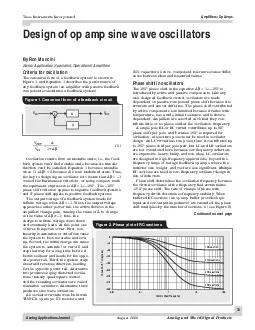
1 Oscillation results from an unstable state ie the feed back system cant find a stable state because its transfer function cant be satisfied Equation 1 becomes unstable when 1A 0 because A0 is an undefined state Thus the key to designing an oscil ID: 26198

Oscillation results from

Share:

Link:

Embed:

Download Presentation from below link

Download Pdf The PPT/PDF document "Analog Applications Journal August Anal..." is the property of its rightful owner. Permission is granted to download and print the materials on this web site for personal, non-commercial use only, and to display it on your personal computer provided you do not modify the materials and that you retain all copyright notices contained in the materials. By downloading content from our website, you accept the terms of this agreement.


Presentation Transcript

Analog Applications Journal back system canÕt find a stable state because its transferfunction canÕt be satisfied. Equation 1 becomes unstable b+=A1AVVIN The 180¡phase shift in the equation AÐ180¡is S VINVOUT AÐ Figure 2. Phase plot of RC sections 0.010.1110100 Continued on next page Figure 3 gives the Wien-bridge circuit configuration. Theis calculated in Equation 2 below.Although two cascaded RC sections provide 180¡phase/dt at the oscillator frequency is low, thus oscillatorsstability. Three equal cascaded RC filter sections have afrequency stability. Adding a fourth RC section producespackages, and the four-section oscillator yields four sinewaves that are 45¡phase shifted relative to each other, solow-frequency resonator.oscillation frequency. The circuit becomes stable when thefacturability, but excess gain causes more distortion of theWhen the gain is too low, oscillations cease under worst-Some circuit configurations (Wien-bridge) or low- Texas Instruments Incorporated Analog Applications Journal Analog and Mixed-Signal ProductsAugust 2000 where s = jwand j = Ö ,311R11VVøöçèæw-w+=++=++++= Figure 3. Wien-bridge circuit schematic 10 k10 n10 k 10 kR 10 nCTLV2471 LampRLRF+V-V Ð+ RCCRVOUT Figure 4. Wien-bridge oscillator withnon-linear feedback Texas Instruments Incorporated Analog Applications Journal is noticeable. Figure 4shows a Wien-bridge circuit withship between the lamp current and resistance keeps outputA typical Wien-bridge oscillator with an AGC circuit is/2 = 2.5 V.are independent of each other. Then Equation 3 is written:The loop phase shift is Ð180¡when the phase shift of eachbecause the tangent 60¡= 1.73. The magnitude of 31AA÷øöçèæ+=b assumption that the RC sections do not load each other.the single op amp phase-shift oscillator is losing popularity. Figure 5. Wien-bridge oscillator with AGC RCRCRF+V-VVOUT RGQ1R1R2D1C1 +Ð Figure 6. Phase-shift oscillator (one op amp) TLV2471RRR Continued on next page Texas Instruments Incorporated Analog Applications Journal other, hence the buffered phase-shift oscillator performsting resistor, Rbe obtained from either phase-shift oscillator, but the purestoscillator, but the three RC sections are configured so thateach section contributes 90¡of phase shift. The outputsa 90¡phase shift between op amp outputs (see Figure 8). RCs) ÷øöçèæ++÷øöçèæ=bCRs(CR1sCRsCR1A22333311 Figure 8. Quadrature oscillator 1/2 TLV24721/2 TLV2472 Ð Ð Continued from previous page 2.5 V+ 5 V+Ð OUT1.5 M180 kRGRF10 k10 nRC 1/4 TLV2474 1/4 TLV24741/4 TLV2474 Texas Instruments Incorporated Analog Applications Journal another phase-shift oscillator, but itFour RC sections require 45¡phase shift45¡phase shift, so taking outputs fromalternatesections yields low-impedancedelivers four 45¡phase-shifted sineThe gain, A, must equal 4 for oscillation to occur. Theideal gain of 4. With low gain, A, and low bias current opamps, the gain setting resistor, RRC section thus insuring oscillator frequency accuracy. Verybiased at 0.5 V to set the quiescent output voltage at 2.5 V.but it has no effect on the oscillator frequency.to feedback capacitance. Voltage feedback op amps are TanPhase 4121j1144==÷øöçèæ+=b 41AA÷øöçèæ+=b Figure 9. Bubba oscillator 0.5 V+5 V Ð Ð Ð 360 kRGRF10 k10 nRC +Ð10 kR 4/4TLV2474 10 nC10 k10 kRR10 nC10 nCVOUTCosineVOUTSine The Wien-bridge oscillator has few parts, and its fre-quency stability is good. Taming the distortion in a Wien-especially the Bubba oscillator, have less distortion coupledwith good frequency stability. The improved performanceloadan Acrobat Reader file at www-s.ti.com/sc/techlit/the materials listed below.Document TitleTI Lit. #1.ÒFeedback Amplifier Analysis ToolsÓ . . . . . .sloa017Related Web siteswww.ti.com/sc/amplifierswww.ti.com/sc/docs/products/analog/tlv2471.htmlwww.ti.com/sc/docs/products/analog/tlv2472.htmlwww.ti.com/sc/docs/products/analog/tlv2474.html