/
Department of Electrical Engineering IIT, Kanpur. India. 208016 {rajat Department of Electrical Engineering IIT, Kanpur. India. 208016 {rajat

Department of Electrical Engineering IIT, Kanpur. India. 208016 {rajat - PDF document

test
test . @test
Follow
402 views
Uploaded On 2016-08-06

Department of Electrical Engineering IIT, Kanpur. India. 208016 {rajat - PPT Presentation

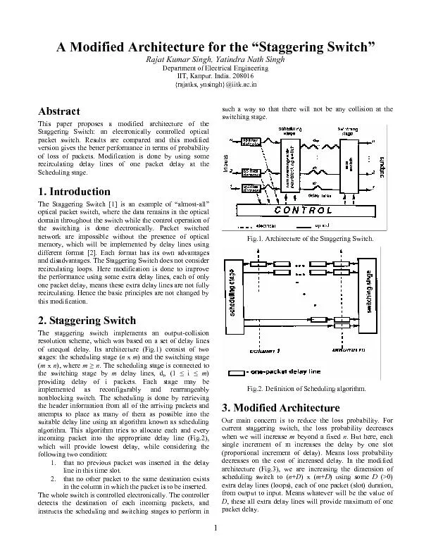
Fig1 Architecture of the Staggering Switch Fig2 Definition of Scheduling algorithm 3 Modified Architecture Our main concern is to reduce the loss probability For current staggering switch ID: 435895

Fig.1. Architecture the

Share:

Link:

Embed:

Download Presentation from below link

Download Pdf The PPT/PDF document "Department of Electrical Engineering IIT..." is the property of its rightful owner. Permission is granted to download and print the materials on this web site for personal, non-commercial use only, and to display it on your personal computer provided you do not modify the materials and that you retain all copyright notices contained in the materials. By downloading content from our website, you accept the terms of this agreement.


Presentation Transcript

Department of Electrical Engineering IIT, Kanpur. India. 208016 {rajatks, ynsingh}@iitk.ac.in This paper proposes a modified architecture of the Staggering Switch: an electronically controlled optical packet switch. Results are compared and this modified version gives the better performance in terms of probability Fig.1. Architecture of the Staggering Switch. Fig.2. Definition of Scheduling algorithm. 3. Modified Architecture Our main concern is to reduce the loss probability. For current staggering switch, the loss probability decreases when we will increase beyond a fixed . But here, each single increment of m increases the delay by one slot (proportional increment of delay). Means loss probability decreases on the cost of increased delay. In the modified architecture (Fig.3), we are 2 Fig.3. Modified Architecture These extra delay lines are used to carry the packets, which are going to be lost in the current slot due to non availability of suitable delay line d, while considering the two conditions. In the next slot, the priority for choosing the will be given to these extra delay lines at the input of scheduling switch. The data in these extra lines will be deleted after every slot. Thus any packet will be lost permanently: if such packet, after delayed by these extra lines, may not be absorbed in any of d delay lines in the next slot if such packet is not able to be placed in any of delay lines and extra delay lines are full for that Loss probability is calculated for different values of and compared to the case of =0. Here, D=0 refer to the previous case (i.e. non modified). Simulation was done using matlab program for the scheduling algorithm and probability of loss is caculated for different no. of extra delay lines, keeping . Results are compared for both cases of (NO and ) extra delay lines. As indicated in the plots (Fig.4-6), the loss probability decreases when increases for different values of probability of arrival and a particular Fig.4 Loss probability Vs Arrival probability for n=m=8 and various D. Fig.5 Loss probability Vs Arrival probability for n=m=12 and various D. Fig.6 Loss probability Vs Arrival probability for n=m=16 and various D. 5. Conclusion It is advantageous to add extra delay lines, instead of increasing the beyond , to reduce the loss probability. This will also results in the improvement of delay performance of the whole system. . Z. Hass, “The Staggering Switch: An Electronically Controlled Optical Packet Switch”, IEEE Journal of Lightwave Technology, pp 925-936, May/June 1993. 993. D. K. Hunter et al., “Buffering in Optical Packet Switches”, IEEE Journal of Lightwave Technology, pp 2081-2094, December 1998.