/
Diagnostic X-rays and CT Scans Diagnostic X-rays and CT Scans

Diagnostic X-rays and CT Scans - PowerPoint Presentation

test
test . @test
Follow
389 views
Uploaded On 2016-04-27

Diagnostic X-rays and CT Scans - PPT Presentation

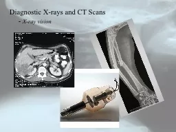
Xray vision httpwwwbjwinslowcomalbumsmedicalchartsbrokenarmradiusandulnaxray10jpg httpwwwmuseumboerhaavenlAAcollectionAAJPEGSM229955jpg httpwwwuabedusurgonccasesGIcase2ctscanofhtm ID: 295824

ray rays energy diagnostic rays ray diagnostic energy scans electron interactions beam material matter intensity photon electrons body detector http incident produces

Share:

Link:

Embed:

Download Presentation from below link

Download Presentation The PPT/PDF document "Diagnostic X-rays and CT Scans" is the property of its rightful owner. Permission is granted to download and print the materials on this web site for personal, non-commercial use only, and to display it on your personal computer provided you do not modify the materials and that you retain all copyright notices contained in the materials. By downloading content from our website, you accept the terms of this agreement.


Presentation Transcript

Slide1

Diagnostic X-rays and CT Scans - X-ray vision

http://www.bjwinslow.com/albums/medicalcharts/broken_arm_radius_and_ulna_x_ray_10.jpg

http://www.museumboerhaave.nl/AAcollection/AAJPEGS/M22/9955.jpg

http://www.uab.edu/surgonc/cases/GI/case2/ctscanof.htmSlide2

Diagnostic X-rays and CT Scans - motivation and outline

X-rays have been known for over 110 years.

X-rays are the most utilized modern medical technique.

“X-rays” in the colloquial sense are actually radiographs – intensity mappings of the shadows created when an x-ray beam passes through materials.

The x-rays are absorbed as they pass through tissue and bone and what emerges is displayed on a film or stored digitally (called a

CT

or computed tomography

scan) and used to reconstruct an image of the object that absorbed the x-rays.

One limitation of film x-rays is their lack of depth information.

A

CT

or computed tomography scan can distinguish the different absorbing layers since the images are stored electronically and can be processed separately.

Diagnostic x-rays are a type of ionizing radiation and there are inherent risks associated with an x-ray scan.Slide3

Even though x-rays produce ionizing radiation, the risks seem to be negligible, with small doses of radiation, compared to the medical benefits.

We’ll investigate x-ray production and then use it to produce a radiograph.

In order to produce a radiograph we need to determine how the x-rays interact with body tissues and bones.

Then we will see how organs, which normally cannot be imaged with x-rays, can be imaged by using a suitable contrast medium.

Then we’ll investigate computed tomography and see how to digitally reconstruct x-ray images.

Two applications will be considered, x-rays in dentistry and lung cancer.

Diagnostic X-rays and CT Scans

-

motivation and outlineSlide4

Diagnostic X-rays and CT Scans - Production of x-rays

http://openlearn.open.ac.uk/file.php/3318/S809_1_004i.jpg

Free electrons are produced at a (usually tungsten) filament and these free electrons are accelerated to the right by an electric field that is generated between the cathode (-) to the anode (+) by applying a potential difference across the cathode/anode.

To produce these electrons the filament is heated by passing an electric current through the (tungsten) wire and the electrons are thermally emitted.

The anode geometry could be fixed or rotatable. Here we have a rotatable anode.

The material that the anode is constructed from will determine the type of x-rays that are generated and their energies.

The kinetic energy of the electron is given by

q

D

V

and the energies are usually several

keV

’s

.

Most of the electrons energy goes to heating the anode, but some will produce x-rays.Slide5

Diagnostic X-rays and CT Scans - Production of x-rays

The heat has to be removed or the x-ray tube will suffer damage.

- usually the anode will melt. Usually these x-ray units are water cooled.

A rotating anode spreads out the heat so that it can be dissipated over a larger area.

There are two mechanisms to produce x-rays from the anode.

Bremsstrahlung – or braking radiation

The electrons are slowed down, or decelerated, and the accelerating charge produces a continuous emission of radiation.

This is exactly how a light bulb works, except the electron energies are much less.

electrical interactions (forces) between the electrons and the atomic nucleus of the anode decelerate the electrons.Slide6

Diagnostic X-rays and CT Scans - Production of x-rays

http://

www.astro.wisc.edu/~bank/index.html

Diagram of the Bremmstrahlung process.

The electrons interaction is electromagnetic in nature.

As the electron decelerates radiation is produced all along its path.

Depending on how the electron interacts with the nucleus will determine its energy.

Glancing collisions produce low energy x-rays while “head-on” collisions convert almost all of the energy of the electron into an x-ray.Slide7

Diagnostic X-rays and CT Scans - Production of x-rays

The second mechanism for x-ray production is called

PIXE

or particle induced x-ray emission.

The high energy electron can knock out an inner shell electron from the target atom and this creates a vacancy in the inner shell.

In order to conserve energy an electron from a higher orbital will transition to the inner orbital, with an emission of a photon in the x-ray portion of the EM spectrum.

Of course, you don’t have to use electrons – you could use protons. This is what’s done using the accelerator in the basement.

The x-rays produced are characteristic of the anode material.

http://www.helmholtz-muenchen.de/uploads/pics/pixe_2_textmedium.jpegSlide8

Diagnostic X-rays and CT Scans - The characteristic x-ray spectrum

http://www.msm.cam.ac.uk/doitpoms/tlplib/xray-diffraction/images/spectra.gif

The total spectrum is the sum of the contributions due to Bremmstrahlung and PIXE.

The incident electrons eject inner shell electrons from the target material and this produces characteristic x-rays with a given energy or wavelength.

In addition, those incident electrons that don’t eject inner shell electrons of the target material will however undergo glancing interactions and this produces the braking deceleration and this produces the continuum of background.

This is the emission spectrum for Cu and the energy of the photons determines the wavelength of the x-ray throughSlide9

Diagnostic X-rays and CT Scans - The characteristic x-ray spectrum

The characteristic x-ray energies are due to the transitions that the electron makes from the higher orbital to the lower orbital.

The two highest energy transitions are called the K

a

and K

b, for the electron being ejected from the innermost shell, termed the K-shell.

The highest probability transition is the Ka

and the lower probability transition is the Kb

and these are seen by intensity in the emission spectrum.

http://www.msm.cam.ac.uk/doitpoms/tlplib/xray-diffraction/images/spectra.gifSlide10

Diagnostic X-rays and CT Scans - The Interactions of X-rays and Matter

X-rays interact with matter in two ways

Photoelectric Effect

Compton Effect

These two effects are responsible for the absorption and scattering of x-rays and thus the ultimate quality of the radiograph.

The photoelectric effect dominates for x-rays with energies lower than about 25 keV

.

The incoming

x-ray photon

interacts with inner shell electrons of usually light elements, say C, H, O or N that makes up soft tissues.

The inner shell electron can absorb

ALL

of this photon’s energy

(leading to attenuation of the primary beam) and

the electron can

be

ejected.

Any excess energy (outside what it takes to unbind the electron) shows up as KE in the electron.Slide11

Diagnostic X-rays and CT Scans - The Interactions of X-rays and Matter

The photoelectron is free to travel throughout the body, but in general it only travels a small distance before its energy is reabsorbed.

The vacancy that was created by the production of a photoelectron is quickly filled by a higher orbital electron with an emission of

an x-ray characteristic of the element that produced the photoelectron.

This x-ray photon can be produced in any random direction and is responsible for scattering in the x-ray

beam and is another source of ionizing radiation in th

e body.

The probability that an x-ray photon will

be absorbed or transmitted depends on the

elements in the absorbing material.

In fact, photoelectric absorption increases

with the cube of the atomic number.

http://www.thermo.com/eThermo/CMA/Images/Various/151Image_15772.gifSlide12

Diagnostic X-rays and CT Scans - The Interactions of X-rays and Matter

The photoelectric effect also increases with decreasing photon energy, a consequence of the uncertainty principle.

This interaction produces, again, a photon with the same energy needed to remove the atom’s electron and this is in a random direction.

This lowers the intensity of, or attenuates the incident

beam,

and produces ions in the body.

Most interactions of photons and bones and the ultimately the image receptor (say film) are photoelectric in

nature (because they are dense and higher Z

materials).

Photoelectric events are usually viewed as an elastic collision.

These produce the shadows in the x-ray

film due to photons created

as scattered events in the film or detector

.

High Z materials make for good shielding

devices as the transmission of

the primary photon beam is decreased

.Slide13

Diagnostic X-rays and CT Scans - The Interactions of X-rays and Matter

The other photon-electron interaction is the Compton Effect.

In the Compton effect, which can be viewed as an inelastic collision, the incident photon gives some of its energy to the electron in the atom with which it collides, but the photon is scattered.

The scattered photon has less energy (it transferred momentum to the electron) and this produces longer wavelength radiation in a perhaps different direction than the incident beam.

Here the interaction time is very short in accordance

with the uncertainty principle and the Compton

effect also attenuates the x-ray beam.

The electron recoils at a very high velocity.

Most interactions between x-rays and

soft tissues are Compton scattering events.

http://illumin.usc.edu/_images/pictures/ii9_170_compton.gifSlide14

Diagnostic X-rays and CT Scans - The Interactions of X-rays and Matter

The central theme of radiology

X ray photons are removed from a beam and the energy is given to a medium by a two-stage process:

1. The photon first ionizes the medium’s atoms or molecules by either the

Compton

or photoelectric effects by a collision with an orbital electron and therefore is removed from the beam. This produces anatomic shadow patterns in the beam and is related to what

will be what is imaged.

2. The result produces a high velocity photoelectron or Compton scattered

electron which ionizes hundreds or thousands of other atoms or

molecules

and this produces a medium response, which is usually tissue

damage. This is the origin of radiation dose in the body.Slide15

Diagnostic X-rays and CT Scans - The Interactions of X-rays and Matter

There are functionally three categories of materials with which the x-rays interact.

1. The soft tissues and bones in the body.

2. The materials involved in detecting the radiation that passes through the body.

3. The shielding.

These arise out of the interactions of the x-rays with the material in which they are propagating.Slide16

Diagnostic X-rays and CT Scans - The Interactions of X-rays and Matter

- Photon Removal from the Beam

Photon-electron interactions (photoelectric or Compton effects) remove photons from the incident beam.

The number of photons removed depends on the material in which the photon is incident.

Removing photons from the beam produces the radiographic shadows in the detector material

.

Compton scattered photons are usually useless for imaging since they won’t necessarily strike your detector.

The Compton scattered photons will either get absorbed and deposit energy in the body (which can produce chemical or cellular changes) or simply become background fog on your detector.

The absorption of photons by the photoelectric effect help to provide effective shielding sources such as lead. (In high Z materials the photoelectric effect dominates.)Slide17

Diagnostic X-rays and CT Scans - The Interactions of X-rays and Matter

- Energy deposition in the material

Energy deposition in the body does not help the image formation process.

Could be bad for the body leading to cellular or chemical changes.

- how much is too much? 

Dose For the detector material, it is the subsequent ionization in the material that is used to form the image.

The x-rays that make it to the detecting material interact with the detecting material and these interactions are what’s used to make an image.

For example, in a film the x-rays stimulate and excite a chemical emulsion to expose the film. In a silicon crystal detector, the x-ray creates electron-hole pairs and placing an electric field across the silicon crystal causes the electron-hole pairs to drift and this current is recorded as a measure of the x-ray energy.Slide18

Diagnostic X-rays and CT Scans - The Interactions of X-rays and Matter

The production of a radiograph

The x-ray tube generates the x-rays and the x-rays are produced and spread out through space.

A collimator is placed in the beam’s path and most x-rays get absorbed in the collimator.

A fraction get through and a narrow beam strikes the patient.

These x-rays are mostly absorbed by the body but about 1% make it out and are used to expose a film or to create electrical signals in a detector for image formation.

Wolbarst

, Physics of RadiologySlide19

Diagnostic X-rays and CT Scans - The Interactions of X-rays and Matter

- X-ray Detectors

Radiological film: The emulsion consists of a gelatin material containing an even distribution of the radiation-sensitive silver bromide crystals or grains.

The double emulsions essentially reduce exposure requirements to one-half that required for a single emulsion, but most radiography films have emulsion only on one side.

The interaction of the x-rays with the emulsion material (a cubic lattice of Ag

+

and Br

-

ions) sensitizes (excites) the grains and during the development process this turns the grains black.

The grains not sensitized are removed during the development process.

http://www.tpub.com/content/chemical-biological/TM-1-1500-335-23/css/TM-1-1500-335-23_528.htmSlide20

The net result for film are regions of black (complete sensitization) and regions of various shades of grey.

The degree of sensitization depends on the energy of the incident x-ray.

To determine the energy of the ray on the film or detector we need to look at how materials absorb the x-rays.

Diagnostic X-rays and CT Scans

- T

he Interactions of X-rays and Matter

- X-ray Detectors

http://

rad.usuhs.mil/rad/home/peds/acutepostarrow.jpg

Posterior rib fracture of the left 7th rib as well as lateral fractures of the 4

th

– 6

th

ribs

Typically, this is part of violent shaking. The infant or young child is held very tightly around the chest and squeezed while being shaken. This compresses the ribs front to back and tends to break them next to their attachment to vertebrae and laterally where they are being literally almost folded in half. Therefore, lateral & posterior rib fractures are highly specific for abuse.

The Child Abuse Referral and Education (CARE) Network of the Uniformed Services University of the Health SciencesSlide21

Diagnostic X-rays and CT Scans - The Interactions of X-rays and Matter

- X-ray Detectors

http://

blogs.uslhc.us

/?tag=detector

A typical Si(Li

) X-ray detector

An array of these form the basis for a CT scan.

These are actually lithium drifted silicon detectors – semiconductor devices.

The incident x-ray produces equal and opposite charge carriers that are separated by the application of an electric field.

The subsequent current pulses measured (from each and almost every incident photon (dead time)) are produced on a screen as a function of the intensity at a spot on the detector.

The more time the detector is busy the lower the image quality.

The lower the resolution of your detector the lower the image quality – the detector can’t tell two x-rays apart in energy.Slide22

X-ray attenuation in matter depends on the thickness of the material, the density of the material, and the effective atomic number and the beam energy.

Experimentally these effects are tested by placing different attenuating material in front of an x-ray beam and seeing how much of the incident intensity passes through the material.

It is found that the intensity of the transmitted x-ray beam decreases with increasing thickness as a decaying exponential function.

m

is defined as the linear attenuation coefficient.

m

is a function of density, effective atomic number and the beam energy and x

is the distance traversed by the photons.

m

is independent of the distance traveled by the x-rays.

Diagnostic X-rays and CT Scans

-

T

he Interactions of X-rays and Matter

- X-ray attenuationSlide23

Diagnostic X-rays and CT Scans - The Interactions of X-rays and Matter

- X-ray attenuation

A perhaps more meaningful quantity is the half-value layer or HVL

.

The

HVL is the thickness over which the x-rays travel so as to lose ½ of the incident beam intensity.

These arguments assume a monochromatic x-ray beam passing through a homogenous medium.

The body is neither a homogenous medium nor is the Bremmstrahlung diagnostic

x

- ray beam monochromatic, but we’ll make it work.

An example: The

HVL

for a monochromatic x-ray beam in a material is 3cm. What fraction of the beam’s original intensity remains after passage through 9cm of material?Slide24

Diagnostic X-rays and CT Scans - The Interactions of X-rays and Matter

- X-ray attenuation

For many different layers of materials, we can generalize the intensity function to include these layers. For layers of thickness,

x

1, x

2, … and attenuation coefficients m

1,

m2

, …

in each of these layers, we have for the intensity transmitted through all the layers

This of course means that the attenuated intensity is the beam intensity minus the intensity transmitted.

The intensity absorbed by the body will eventually need to be worried about.

These absorbed intensities are related to the dose your

body gets.Slide25

Diagnostic X-rays and CT Scans - The Interactions of X-rays and Matter

- X-ray attenuation

Another example: Suppose that 60 keV

x-rays are needed to pass through two layers of material, one of which is 3cm of soft tissue (

mm = 0.2045 cm

2/g with density rst

= 1 g/cm

3) and the second is 1cm of bone (0.2824 cm

2

/g and density

r

bone

= 1.65 g/cm

3

). What is the transmitted intensity if the incident intensity is 1 W/m

2

?

m

m

is called the mass absorption coefficient.

This takes into account the density of the material and the atomic number dependence of the linear absorption coefficient.