/
MT TUTORIAL Op Amp Settling Time SETTLING TIME The settling time of an amplifier is defined MT TUTORIAL Op Amp Settling Time SETTLING TIME The settling time of an amplifier is defined

MT TUTORIAL Op Amp Settling Time SETTLING TIME The settling time of an amplifier is defined - PDF document

test
test . @test
Follow
836 views
Uploaded On 2014-12-27

MT TUTORIAL Op Amp Settling Time SETTLING TIME The settling time of an amplifier is defined - PPT Presentation

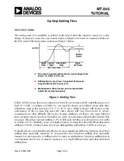
Rev0 1008 WK Page 1 of 4 Error band is usually defined to be a percentage of the step 01 005 001 etc Settling time is nonlinear it may take 30 times as long to settle to 001 as to 01 Manufacturers often choose an error band which makes the op amp lo ID: 30337

Rev0 1008 Page

Share:

Link:

Embed:

Download Presentation from below link

Download Pdf The PPT/PDF document "MT TUTORIAL Op Amp Settling Time SETTLIN..." is the property of its rightful owner. Permission is granted to download and print the materials on this web site for personal, non-commercial use only, and to display it on your personal computer provided you do not modify the materials and that you retain all copyright notices contained in the materials. By downloading content from our website, you accept the terms of this agreement.


Presentation Transcript

MT-046TUTORIAL OUTPUTERRORBAND Unlike a DAC device, there is no natural error band for an op amp (a DAC naturally has an error band of 1 LSB, or perhaps ±1 LSB). So, one mudefinitions, such as the step size (1 V, 5 V, 10 V, etc.). What is chosen will depend on the performance of the op amp, but since the value chosen will vary from device to device, comparisons are often difficult. This is true be MT-046 MEASURING SETTLING TIME Measuring fast settling time to high accuracy is vetop pulses. Large amplitude step voltages will The example test setup shown in Figure 2 below is useful in making settling time measurements on op amps operating in the inverting mode. The signal at the the difference between the output and the input signal, multiplied by the constant k., i.e. the +- V1 R1RR2 ERROR = k(V), k =R1 + R2 Figure 2: Measuring Settling TiThere are many subtleties involved towards making this setup work reliably. The resistances should low in value, to minimize parasitic time constants. The back-back Schottky diode clamps help prevent scope overdrive, and allow high sensitivity. If R1 = R2, then k = 0.5. Thus the error band at the ERROR output will be 5 mV for 0.1% settling with a 10V input step. In some case, a second (very fast) amplifier stage may be used after the false summing node, to increase the signal level. In any case, testing of settling time must be done with a test setup identical to that used by the op amp manufactury. Many modern digitizing oscilloscopes are insensitive to input overdrive and can be used to measure the ERROR waveform directly—this must be verified for each oscilloscope by examining the operating manual carefully. Note that a direct measurement allows measurements of settling time in both the inverting and non-inverting modes. An exampl op amp is shown in Figure 3 below. Nong time to 0.1% is approximately 18 ns. Page 2 of 4 MT-046 OUTPUT2mV (0.1%) / DIV5ns / DIVINPUT 18nsling Time Measured Directly In making settling time measurements of this type, it is also ims, if the op amp under test has a settling time of 20 ns to 0.1%, the app PULSEGENERATOROUTPUT) DUT 100100100R2R1+– +0.5V COAX "FLAT" REGION MAKE AS SHORT AS POSSIBLE,USE GROUND PLANECONNECTIONPREFERRED D2D3 Page 3 of 4 Page 4 of 4 This type of generator can be expensive, but a simple circuit as shown in Figure 4 can be used with a reasonably flat generator The circuit of Fig. 4 works best if low capacitae connections are minimized. A short length of 50 coax can be used to obtained if the test fixture is connected directly to the output of the generatopositive-going pulse at "A" which rises from approximately –1.8 V to +0.5 V in less than 5 ns (assuming the settling time of the DUT is in the orse times may generate ringing, and longer rise times can degrade the DUT settling time; therefore some optimization is get best performance. When threversed biased. The "0V" region of the signal resistor help maintain an approximate 50 termination during the time thREFERENCES Hank Zumbahlen, Basic Linear Design, Analog Devices, 2006, ISBN: 0-915550-28-1. Also available as Linear Circuit Design Handbook , Elsevier-Newnes, 2008, ISBN-10: 0750687037, ISBN-13: 978-0750687034. Chapter 1. Walter G. Jung, Op Amp Applications Analog Devices, 2002, ISBN 0-916550-26-5, Also available as Op Amp Applications Handbook , Elsevier/Newnes, 2005, ISBN 0-7506-7844-5. Chapter 1. Copyright 2009, Analog Devices, Inc. All rights reserved. Analog Devices assumes no responsibility for customer product design or the use or application of customers’ products or for any infringements of patents or rights of others which may result from Analog Devices assistance. All trademarks and logos are property of their respective holders. Information furnished by Analog Devices applications and development tools engineers is believed to be accurate and reliable, however no responsibility is assumed by Analog Devices regarding technical accuracy and topicality of the content provided in Analog Devices Tutorials.