/
in Inches Millimeters7000 SERIESHIGH RELIABILITY REED RELAYS7000 Seri in Inches Millimeters7000 SERIESHIGH RELIABILITY REED RELAYS7000 Seri

in Inches Millimeters7000 SERIESHIGH RELIABILITY REED RELAYS7000 Seri - PDF document

trinity
trinity . @trinity
Follow
342 views
Uploaded On 2021-08-20

in Inches Millimeters7000 SERIESHIGH RELIABILITY REED RELAYS7000 Seri - PPT Presentation

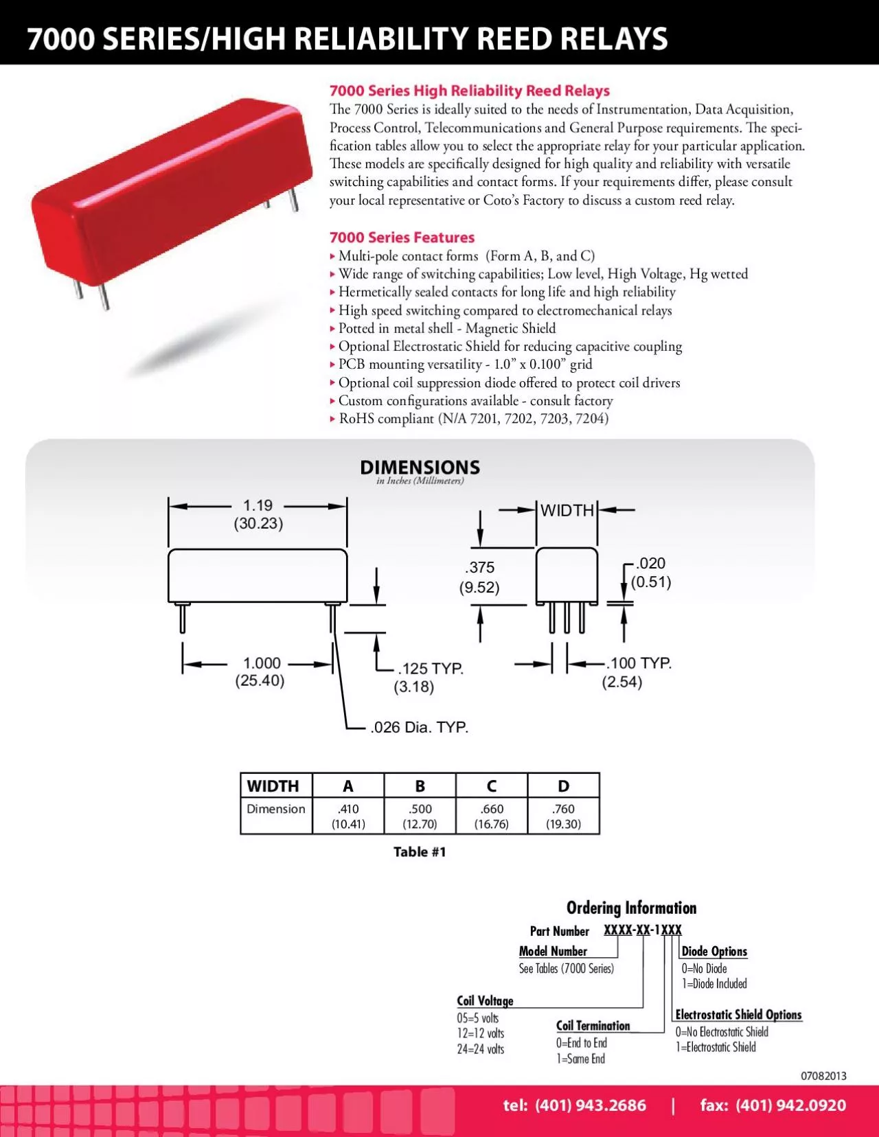
119375100 TYP1000020125 TYPWIDTH95205125430232540318026 Dia TYPOrdering InformationPart NumberXXXXXX1XXXModel NumberSee Tables 7000 SeriesCoil Voltage055 volts1212 volts2424 voltsDiode Options0No Di ID: 867824

018 759 54136e peak 759 018 peak 54136e coil pin 7000 series 24136e max high 401 resist voltagevdc top

Share:

Link:

Embed:

Download Presentation from below link

Download Pdf The PPT/PDF document "in Inches Millimeters7000 SERIESHIGH REL..." is the property of its rightful owner. Permission is granted to download and print the materials on this web site for personal, non-commercial use only, and to display it on your personal computer provided you do not modify the materials and that you retain all copyright notices contained in the materials. By downloading content from our website, you accept the terms of this agreement.


Presentation Transcript

1 in Inches (Millimeters)7000 SERIES/HIGH
in Inches (Millimeters)7000 SERIES/HIGH RELIABILITY REED RELAYS7000 Series High Reliability Reed Relayse 7000 Series is ideally suited to the needs of Instrumentation, Data Acquisition, Process Control, Telecommunications and General Purpose requirements. e speci 1.19 .375 .100 TYP. 1.000 .020 .125 TYP.WIDTH(9.52)(0.51)(2.54)(30.23)(25.40)(3.18) .026 Dia. TYP. Ordering Information Part NumberXXXX-XX-1XXX Model NumberSee Tables (7000 Series) Coil V oltage 05=5 volt s 12=12 volt s 24=24 volt sDiode Options0=No Diode1=Diode Included Electrostatic Shield Options 0=No Electrostatic Shield1=Electrostatic ShieldCoil Termination0=End to End 1=Same End Table #1 WIDTHDimension.410(10.41).500(12.70).660(16.76).760(19.30)tel: (401) 943.2686 | fax: (401) 942.0920 30 | page07082013 Notes:Consult factory for life expectancy at other switching loads.Optional coil suppression diode Pin #1 is +.Hg Content: Form A, 0.04 grams per capsule; Form C, 0.072 grams per capsule.Environmental Ratings:Storage Temp: -35°C to 100°C; Operating Temp: -20°C to 85°C; Solder Temp: 270°C max; 10 sec. maxAll electrical parameters measured at 25°C unless otherwise specied.Vibration: 20 G’s to 2000 Hz; Shock: 50 G’s COTO TECHNOLOGY, INC.For most recent data visit www.cotorelay.compage | 31 7000 SERIESParametersTest ConditionsForm A, BForm CForm AHg WettedForm AHighVoltageCONTACT RATINGSSwitching VoltageMax DC/Peak AC Resist.Volts200150500500Switching CurrentMax DC/Peak AC Resist.Amps0.50.251.00.5Carry CurrentMax DC/Peak AC Resist.Amps2.00.52.02.0Contact RatingMax DC/Peak AC Resist.WattsLife Expectancy-TypicalSignal Level 1.0V, 10mAx 10 Ops.10001001000100Static ContactResistance (max. init.)50mV, 10mA0.1000.1500.0750.100Dynamic ContactResistance (max. init.)0.5V, 50mAat 100 Hz, 1.5 msec0.1500.2000.1000.150RELAY SPECIFICATIONSInsulation Resistance(minimum)Between all Isolated Pinsat 100V, 25°C, 40% RHCapacitance - Typical Across Open ContactsNo ShieldShield Guarding1.00.22.01.01.00.21.00.2Dielectric Strength(minimum)Between ContactsContacts to ShieldContacts/Shield to CoilVDC/peak AC VDC/peak ACVDC/peak AC2501000150020010001500100010001500120010001500Operate Time - including bounce - TypicalAt Nominal Coil Voltage,30 Hz Square Wavemsec.1.02.02.01.0Release Time - Typicalmsec. 0.12.51.00.1Dot stamped on top of relayrefers to pin #1 location(See following

2 pages for schematicdiagrams and coil dat
pages for schematicdiagrams and coil data.) 07082013 7000 SERIES/HIGH RELIABILITY REED RELAYStel: (401) 943.2686 | fax: (401) 942.0920 32 | page Contact FormModel NumberNominalCoilVoltageVDCMustOperate VoltageVDC max.MustRelease VoltageVDC min.CoilResistance±10% @25ºCWidth(See Table #1)Schematic Top View2,5End to End Same EndCoil Coil1A71013.759.018.00.41.02.030016004200 24136E 54136E 71023.759.018.00.41.02.015010003500 24136E85 54136E78 71033.759.018.00.41.02.01008002400 24136E85710 54136E78910 71043.759.018.00.41.02.05502000 241369857E1210 54136E789101211 71213.759.018.00.41.02.015010003500 24136E58 + 54136E87 + 71413.759.018.00.41.02.017511004200 24136E 54136E 71423.759.018.00.41.02.04901550 24136E85710 54136E79810 71433.759.018.00.41.02.03001350 241369857E1210 54136E789101211 07082013 Notes:ese relays contain bias magnets. Correct coil polarity must be observed.Dot stamped on top of relay refers to pin #1 location. E-pin indicates Electrostatic shield pin. Unused pins omitted. Pin numbers for reference only.All models with Hg wetted contacts are position sensitive, must be mounted within 30 of vertical plane. See schematic. COTO TECHNOLOGY, INC.For most recent data visit www.cotorelay.compage | Contact FormModel NumberNominalCoilVoltageVDCMustOperate VoltageVDC max.MustRelease VoltageVDC min.CoilResistance±10% @25ºCWidth(See Table #1)Schematic Top View2,5End to End Same EndCoil Coil1Awetted72013.759.018.00.41.02.04501785 24136EUP 54136EUP wetted72023.759.018.00.41.02.03401330 24136E85UP 54136E78UP wetted72033.759.018.00.41.02.03001200 2413 6E 85 710UP 54136E78910UP wetted72043.759.018.00.41.02.0250 241369857E1210UP 54136E 78 910 1211UP 1AHighVoltage73013.759.018.00.41.02.017511004200 24136E 54136E HighVoltage73023.759.018.00.41.02.01006402450 24136E 85 54136E 78 HighVoltage73033.759.018.00.41.02.04901550 24136E 85 710 54136E 78 910 HighVoltage73043.759.018.00.41.02.03001350 241369 85 7 E1210 54136E 78 910 1211 07082013 Notes:ese relays contain bias magnets. Correct coil polarity must be observed. Dot stamped on top of relay refers to pin #1 location. E-pin indicates Electrostatic shield pin. Unused pins omitted. Pin numbers for reference only. All models with Hg wetted contacts are position sensitive, must be mounted within 30 of vertical plane. See schematic. COT

3 O TECHNOLOGY, INC.For most recent data v
O TECHNOLOGY, INC.For most recent data visit www.cotorelay.com Contact FormModel NumberNominalCoilVoltageVDCMustOperate VoltageVDC max.MustRelease VoltageVDC min.CoilResistance±10% @25ºCWidth(See Table #1)Schematic Top View2,5End to End Same EndCoilCoil1Awetted72013.759.018.00.41.02.04501785 24136EUP 54136EUP wetted72023.759.018.00.41.02.03401330 24136E85UP 54136E78UP wetted72033.759.018.00.41.02.03001200 2413 6E 85 710UP 54136E78910UP wetted72043.759.018.00.41.02.0250 241369857E1210UP 54136E 78 910 1211UP 1AHighVoltage73013.759.018.00.41.02.017511004200 24136E 54136E HighVoltage73023.759.018.00.41.02.01006402450 24136E 85 54136E 78 HighVoltage73033.759.018.00.41.02.04901550 24136E 85 710 54136E 78 910 HighVoltage73043.759.018.00.41.02.03001350 241369 85 7 E1210 54136E 78 910 1211 07082013 7000 SERIES/HIGH RELIABILITY REED RELAYStel: (401) 943.2686 | fax: (401) 942.0920 Contact FormModel NumberNominalCoilVoltageVDCMustOperate VoltageVDC max.MustRelease VoltageVDC min.CoilResistance±10% @25ºCWidth(See Table #1)Schematic Top View2,5End to End Same EndCoilCoil1A71013.759.018.00.41.02.030016004200 24136E 54136E 71023.759.018.00.41.02.015010003500 24136E85 54136E78 71033.759.018.00.41.02.01008002400 13 54136E78910 71043.759.018.00.41.02.05502000 241369857E1210 54136E789101211 71213.759.018.00.41.02.015010003500 24136E58 + 54136E87 + 71413.759.018.00.41.02.017511004200 24136E 54136E 71423.759.018.00.41.02.04901550 24136E85710 54136E79810 71433.759.018.00.41.02.03001350 241369857E1210 54136E789101211 07082013 Notes: Consult factory for life expectancy at other switching loads. ptional coil suppression diode Pin #1 is +. Hg Content: Form A, 0.04 grams per capsule; Form C, 0.072 grams per capsule.Environmental Ratings:Storage Temp: -35°C to 100°C; Operating Temp: -20°C to 85°C; Solder Temp: 270°C max; 10 sec. maxAll electrical parameters measured at 25°C unless otherwise specied.Vibration: 20 G’s to 2000 Hz; Shock: 50 G’s COTO TECHNOLOGY, INC.For most recent data visit www.cotorelay.com 7000 SERIESParametersTest ConditionsUnitsForm A, BForm CForm AHg WettedForm AHighVoltageCONTACT RATINGSSwitching VoltageMax DC/Peak AC Resist.Volts200150500500Switching CurrentMax DC/Peak AC Resist.Amps0.50.251.00.5Carry CurrentMax DC/Peak AC Resist.Amps2.00.52.02.0Contact RatingMax DC/Peak AC Resist.WattsLife Expectancy-TypicalSig

4 nal Level 1.0V, 10mAx 10 Ops.10001001000
nal Level 1.0V, 10mAx 10 Ops.10001001000100Static ContactResistance (max. init.)50mV, 10mA0.1000.1500.0750.100Dynamic ContactResistance (max. init.)0.5V, 50mAat 100 Hz, 1.5 msec0.1500.2000.1000.150RELAY SPECIFICATIONSInsulation Resistance(minimum)Between all Isolated Pinsat 100V, 25°C, 40% RHCapacitance - Typical Across Open ContactsNo ShieldShield Guarding1.00.22.01.01.00.21.00.2Dielectric Strength(minimum)Between ContactsContacts to ShieldContacts/Shield to CoilVDC/peak AC VDC/peak ACVDC/peak AC2501000150020010001500100010001500120010001500Operate Time - including bounce - TypicalAt Nominal Coil Voltage,30 Hz Square Wavemsec.1.02.02.01.0Release Time - Typicalmsec. 0.12.51.00.1Dot stamped on top of relayrefers to pin #1 location(See following pages for schematicdiagrams and coil data.) 07082013 in Inches (Millimeters)7000 SERIES/HIGH RELIABILITY REED RELAYS7000 Series High Reliability Reed Relayse 7000 Series is ideally suited to the needs of Instrumentation, Data Acquisition, Process Control, Telecommunications and General Purpose requirements. e speci-cation tables allow you to select the appropriate relay for your particular application. ese models are specically designed for high quality and reliability with versatile switching capabilities and contact forms. If your requirements dier, please consult your local representative or Coto’s Factory to discuss a custom reed relay.7000 Series FeaturesMulti-pole contact forms (Form A, B, and C) Wide range of switching capabilities; Low level, High Voltage, Hg wettedHermetically sealed contacts for long life and high reliabilityHigh speed switching compared to electromechanical relaysPotted in metal shell - Magnetic ShieldOptional Electrostatic Shield for reducing capacitive couplingPCB mounting versatility - 1.0” x 0.100” gridOptional coil suppression diode oered to protect coil driversCustom congurations available - consult factory RoHS compliant (N/A 7201, 7202, 7203, 7204) 1.19 .375 .100 TY 1.000 .020 .125 TY .026 Dia. TY Ordering Information Part NumberXXXX-XX-1XXX See Tables (7000 Series) Coil V oltage 05=5 volt s 12=12 volt s 24=24 volt sDiode Options1=Diode Included Electrostatic Shield Options Coil Termination 1=Same End Table #1 WIDTHABCDDimension.410(10.41).500(12.70).660(16.76).760(19.30)tel: (401) 943.2686 | fax: (401) 942.0920 07082013