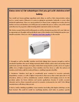
/
Fiber PVC Tubing Braided Fiber Sheath Stainless Steel Coil Fiber PVC Tubing Braided Fiber Sheath Stainless Steel Coil

Fiber PVC Tubing Braided Fiber Sheath Stainless Steel Coil - PDF document

trish-goza
trish-goza . @trish-goza
Follow
497 views
Uploaded On 2014-12-15

Fiber PVC Tubing Braided Fiber Sheath Stainless Steel Coil - PPT Presentation

0mm Fiber 52 mm Stainless Steel Helical Coil brPage 8br brPage 9br brPage 10br brPage 11br brPage 12br ID: 24428

0mm Fiber Stainless

Share:

Link:

Embed:

Download Presentation from below link

Download Pdf The PPT/PDF document "Fiber PVC Tubing Braided Fiber Sheath St..." is the property of its rightful owner. Permission is granted to download and print the materials on this web site for personal, non-commercial use only, and to display it on your personal computer provided you do not modify the materials and that you retain all copyright notices contained in the materials. By downloading content from our website, you accept the terms of this agreement.


Presentation Transcript

STANDARDTABLESWhile the fibers will work over the entire operating range listed, it is recommended that one selects the fiber with the longesat your wavelength of interest. For instance, for 780 nm work we recommend selecting SMF-780-5/125 fiber over SMF-633-4/125 fiber.If the fiber is used at wavelengths less than the cutoff wavelength, the fiber will still transmit light. However it will begin to behave like a multimode fiber. This is not (i.e., NA= [NAmore accurate technique is to use the Mode Field Diameter (MFD) for the light within the fiber to determine the far field. We being essentially Gaussian in behavior. If we then define the effective numerical aperture (NAeffintensity drops to 1/eeffMFD. We have listed NAeffwavelength in the table.cable. For instance, SMF-780-5/125-0.25-Lfiber, which has a 0.25 mm coating diameter, can be cabled with a 0.9mm diameter loose tubing to provide extra protection. DTS0079OZ Optics reserves the right to change any specifications without prior notice.5 July 2018 The following pages list the standard fibers, cables, connectors, lenses, and laser head adaptors available from OZ Optics. Accompanyingeach table are technical notes to help you make the most informed decision possible. Use these tables to pick the best components foryour application. Non-standard components can be made available at the customer's request. Contact OZ Optics for more informatiTable 1A: Standard Singlemode Fibers BarCode Part Number Wavelength Wavelength Diameter(µm) Diameter(µm) Mode FieldDiameter (µm) Attenuation(dB/km) urer's Specs) NumericalAperture(1/e2)3 Jacket orBufferDiameter(mm)4 1197 2/125-0.25-L5 2 ± 1 2.2 (Typical) 200 @340 to 320 nm 0.25 3/125-0.25-L5 125 ± 2 4.0 (Typical) 400 nm 0.12 0.065 @400 nm 0.25 3.5/125-0.25-L5 3.5 ± 0.5 125+3/-1 4.2 (Typical) 488 nm 0.12 488nm 3.5/125-3-L5 3.5 ± 0.5 4.2 (Typical) 488 nm 0.12 488nm 125-0.25-NF-L 125 ± 2 633nm 125-1-L 125 ± 2 633nm 125-3-L 125 ± 2 633nm 125-0.25-L 125 ± 1 0.11 780nm 125-3-L 125 ± 1 0.11 780nm 125-0.25-L 125 ± 0.5 980nm1060nm 2.1 @980 nm1.5 @1060 nm 0.14 0.11 @1060nm 9/125-0.25-L6 125 ± 0.7 1310 nm 10.4 ± 0.8 @1550 nm 1310nm1550nm 0.14 1300nm 1550nm 9/125-1-L6 125 ± 0.7 1310 nm 10.4 ± 0.8 @1550 nm 1310 nm1550 nm 0.14 1300nm1550nm 11788 9/125-2-L6 125 ± 0.7 1310 nm 10.4 ± 0.8 @1550 nm 1310 nm1550 nm 0.14 1300nm1550nm 9/125-3-L6 125 ± 0.7 1310 nm 10.4 ± 0.8 @1550 nm 1310 nm1550 nm 0.14 0.090 @1300 nm0.095 @1550 nm 3.0 7/125-0.25-L 125 ± 1 8 µm @1950 nm N/A 0.155 @1950 nm 0.25 1 All standard polarization maintaining (PM) fibers are based on the PANDAPM fiber structure. Other types are available on requesWhile the fibers will work over the entire operating range listed, it is recommended that one selects the fiber with the longesyour wavelength of interest. For instance, for 820nm work we recommend selecting PMF-850-5/125 fiber over PMF-633-4/125 fiber.If the fiber is used at wavelengths less than the cutoff wavelength, the fiber will still transmit light. However it will begin to behave like amultimode fiber. It will no longer worklike a polarization maintaining fiber. (i.e., NA= [Nield behavior of light from the fiber. Amoreaccurate technique is to use the Mode Field Diameter (MFD) for the light within the fiber to determine the far field. We can tressentially Gaussian in behavior. If we then define the effective numerical aperture (NAeff) of the fiber as being the sineof the angle from the center to where the intensity drops to 1/eeffMFD. We havelisted NAeffwavelength in the table.The jacket diameters listed are for those fiber that come from the manufacturer pre-cabled. For short lengths of fibers OZ Optics can cable the fibers in a loose tube cable. For instance, PMF-1550-8/125-0.4-Lfiber, which has a 0.4mm coating diameter, can be cabled with a 0.9mm diameter loose tubing tSingle clad passive PM fiber.Table 2A: Standard Polarization Maintaining Fibers Code Part Number Wavelength Wave- Diameter(µm) Diameter(µm) Mode FieldDiameter(µm) (dB/km) Specs) NumericalAperture(1/e2)4 Jacket orBufferDiameter(mm)5 Material Crosstalk 2/125-0.25-L 2.3 @350 nm2.6 @405 nm Acrylate 3/125-0.25-L6 3.1 (Typical) 0.11 0.082 @400 nm 0.9 Acrylate 1170 3.5/125-1-L6 3.8 (Typical) 0.11 0.082 @488 nm 0.9 Acrylate /Nylon 1172 125-0.25-L 4.5 (Typical) 0.11 0.089 @633 nm 0.25 Acrylate 1174 125-1-L 4.5 (Typical) 0.11 0.089 @633 nm 0.9 Acrylate /Nylon 1181 125-0.4-L 5.5 ± 1 0.11 0.098 @850 nm 0.40 Acrylate 125-0.25-L 5.5 ± 1 0.11 0.098 @850 nm 0.25 Acrylate 125-0.4-L 6.6 ± 1 0.11 0.095 @980 nm 0.40 Acrylate 125-0.25-L 6.6 ± 1 0.11 0.095 @980 nm 0.25 Acrylate 7/125-0.25-L 9.5 ± 1 0.11 0.088 @1310 nm 0.25 Acrylate 1194 8/125-0.4-L 10.5 ± 1 0.11 0.094 @1550 nm 0.40 Acrylate 8/125-0.25-L 10.5 ± 1 0.11 0.094 @1550 nm 0.25 Acrylate 7/125-0.25-L 125 ± 1 8.0 0.155 @1950 nm 0.25 Acrylate Table 1B: Large Mode Area Fibers Wavelength Diameter(µm) Diameter(µm) Attenuation (dB/km) Numerical Aperture BufferDiameter(mm) Buffer Material 36269 Table 2B: PMLarge Mode Area Fibers Bar Code Wavelength Wave- Diameter(µm) Diameter(µm) (dB/km) Specs) Jacket orBufferDiameter(mm)5 Material Crosstalk 980-1100 Acrylate 920-1100 Acrylate 920-1100 Acrylate 2 Table 4: Standard Step Index Multimode Fibers For Visible And Ultraviolet Wavelengths The attenuation of these fibers is highly wavelength dependent. For detailed attenuation versus wavelength data contact OZ Opti, while the NAof the focused rays shouldbe between 30% and 90% of the NAof the fiber. We strongly recommend using high power, air gap design connectors for very high pPower handling for pulsed laser light is dependent on the pulse energy, duration, and wavelength. Contact OZ for power handling for pulsed laser applications.While OZ Optics believes this information to be reliable, it is only provided as a general guide, and can be greatly affected by individual circumstances. OZ Optics offers no warranties as to its accuracy, and disclaims any liability in connection to its use. BarCode Part Number Wavelength CoreDiameter(µm) Diameter(µm) Coatings(µm) (dB/km)1 Aperture Jacket orBufferDiameter(mm) Material 10 ± 2 N/A 380-870 nm 0.10 Fused Silica 1251 25 ± 4 N/A 380-870 nm 0.10 Fused Silica 1259 50 ± 1 N/A 300-900 nm220-300 nm 0.22 Fused Silica 1253 50 ± 1 N/A 300-900 nm220-300 nm 0.12 Fused Silica 1271 100 ± 2 N/A 300-900 nm220-300 nm 0.22 Fused Silica 1287 200 ± 5 260 ± 5 380-900 nm250-380 nm 0.22 Fused Silica 27638 300± 6 Buffer 300-900 nm220-300nm 0.22 Fused Silica 1294 365 ± 10 425 ± 10 380-900 nm250-380 nm 0.22 Fused Silica 6068 400± 8 Buffer 300-900 nm220-300nm 0.22 Fused Silica 1793 550 ± 12 630 ± 10 380-900 nm250-380 nm 0.22 Fused Silica 2838 600± 12 Buffer810± 25 300-900 nm220-300 nm 0.22 Fused Silica 27640 800± 16 Buffer 300-900 nm220-300nm 0.22 Fused Silica 1302 940 ± 15 630 ± 10 380-900 nm250-380 nm 0.22 Fused Silica Table 3: Standard Graded Index Multimode Fibers multimode fiber, then the intensity of the output light is 5% of the center intensity at the angle whose sine equals the numerical aperture. This is the definition used for ourcoupler, collimator, and focuser calculations when using these fibers. Assuming that the overall intensity pattern (i.e., ignoring modal noise) is Gaussian in behavior, we Wavelength Range Core Diameter(µm) Diameter (µm) Numerical Aperture2 Jacket or BufferDiameter (mm) 16149 MMF-IRVIS-50/125- 50 ± 3 2.5 @ 850 nm 0.8 @ 1300 nm 0.25 MMF-IRVIS-50/125-1-L 50 ± 3 2.5 @850 nm 0.8 @1300 nm 0.9 MMF-IRVIS-50/125-3-L 50 ± 3 2.5 @850 nm 0.8 @1300 nm 3.0 MMF-IRVIS-62.5/ 62.5 ± 3 3.0 @850 nm 0.7 @1300 nm 0.25 MMF-IRVIS-62.5/ 62.5 ± 3 3.0 @850 nm 0.7 @1300 nm 0.9 MMF-IRVIS-62.5/ 62.5 ± 3 3.0 @850 nm 0.7 @1300 nm 3.0 MMF-IRVIS-100/ 100 ± 3 6.0 @850 nm 3.0 @1300 nm 0.9 MMF-IRVIS-100/ 100 ± 3 6.0 @850 nm 3.0 @1300 nm 3.0 3 The attenuation of these fibers is wavelength dependent. For detailed attenuation versus wavelength data contact OZ Optics., while the NAof the focused rays shouldbe between 30% and 90% of the NAof the fiber. We strongly recommend using high power, air gap design connectors for very high pPower handling for pulsed laser light is dependent on the pulse energy, duration, and wavelength. Contact OZ for power handling for pulsed laser applications.While OZ Optics believes this information to be reliable, it is only provided as a general guide, and can be greatly affected by individual circumstances. OZ Optics offersno warranties as to its accuracy, and disclaims any liability in connection to its use. BarCode Part Number Wavelength CoreDiameter(µm) Diameter(µm) Other Coatings(µm) (dB/km)1 Aperture Jacket orBufferDiameter(mm) Material QMMF-IRVIS-50/125-0.25-L 50 ± 2 N/A 10dB peak @1390 nm630-1800 nm 0.22 Fused Silica 1263 QMMF-IRVIS-50/125-3-L 50 ± 2 N/A 20dB peak @1390 nm630-1800 nm 0.22 Fused Silica 1268 QMMF-IRVIS-100/140-0.25-L 100 ± 2 N/A 20dB peak @1390 nm630-1800 nm 0.22 Fused Silica 1282 QMMF-IRVIS-200/230-0.5-L 200 ± 4 N/A 20 @530-1100 nm29 @1300 nm 0.37 QMMF-IRVIS-200/240-0.4-L 200 ± 5 630-1900 nm 0.22 Fused Silica 2512 QMMF-IRVIS-300/330-0.65-L 300 ± 6 N/A 20 @530-1100 nm29 @1300 nm 0.37 QMMF-IRVIS-365/400-0.73-L 365 ± 14 20dB peak @1390 nm630-1800 nm 0.22 Fused Silica 1809 QMMF-IRVIS-400/430-0.73-L 400 ± 8 N/A 20 @530-1100 nm29 @1300 nm 0.37 QMMF-IRVIS-400/440-0.6-L 400 ± 8 Buffer 540 ± 17 20dB peak @1390 nm630-1800 nm 0.22 Fused Silica 1298 QMMF-IRVIS-550/600-0.75-L 550 ± 12 630-1900 nm 0.22 Fused Silica 1299 QMMF-IRVIS-600/630-1-L 600 ± 10 N/A 20 @530-1100 nm29 @1300 nm 0.37 QMMF-IRVIS-940/1000-1.4-L 940 ± 15 0.22 Fused Silica 1303 QMMF-IRVIS-1000/1035-1.4-L 1000 ± 15 N/A 20 @530-1100 nm29 @1300 nm 0.37 Table 5: Standard Step Index Multimode Fibers For Infrared And Visible Wavelengths Table 6A: Standard Connectors And Connector Finishes* ConnectorCode Connector Type Endface Polish2 (Free Space) Return Loss(Connected)4 Comments 1.8 mm diameter ferrule Flat -14 dB N/A5 Used for pigtailing only. 1A 1.8 mm diameter ferrule 8 Degree Angled N/A5 Used for pigtailing only. 1.25 1.25 mm diameter ferrule Flat -14 dB N/A5 Used for pigtailing only. 1.25A 1.25 mm diameter ferrule 8 Degree Angled N/A5 Used for pigtailing only. 1.4 1.4 mm diameter ferrule Flat -14 dB N/A5 Used for pigtailing only. 1.4A 1.4 mm diameter ferrule 8 Degree Angled N/A5 Used for pigtailing only. 2F 2 mm diameter ferrule Flat -14 dB N/A5 Used for pigtailing only. 2A 2 mm diameter ferrule 8 Degree Angled N/A5 Used for pigtailing only. 2.5 2.5 mm diameter ferrule Flat -14 dB N/A5 Used for pigtailing only. 2.5A 2.5 mm diameter ferrule 8 Degree Angled N/A5 Used for pigtailing only. 3 NTT-FC -14 dB 1 dB 3S NTT-FC Super PC Standard single mode and polarization maintaining fiber connector. 3U NTT-FC Ultra PC Lower return loss version of the 3S connector. Also highly 3A NTT-FC 8 Degree Angled PC (APC) 3AF NTT-FC 8 Degree Angle Flat (AFC) NA6 Special Angled flat version of the FC design to give low return loss,excellent repeatability for free space couplers and collimators. A3 Adjustable NTT-FC Flat -14 dB NA6 For couplers and collimators designs with adjustable focus. A3A Adjustable NTT-FC 8 Degree Angled PC (APC) NA6 Low return loss version of the A3 connector. 5 SMA905 -14 dB 1 dB 5HP SMA905 Flat, Air Gap -14 dB 1 dB Special version of the SMA-905 connector, with the tip of the fiber 6 SMA906 -14 dB 1 dB Lower losses than SMA-905 when connecting 2 fibers. Not often AT&T-ST Super PC SC Super PC SCU Ultra PC SCA 8 Degree Angled PC (APC) LC Super PC Small form factor connector, to increase connection density. LCU Ultra PC LCA 8 Degree Angled PC (APC) MU Super PC Alternative to the LC design. Used more outside North America. E Super PC Increasingly popular in Europe. Has built in safety shutter. EA 8 Degree Angled PC (APC) Low return loss version of E2000 connector. MD Super PC Miniature connector for dense connector packaging. MDA 8 Degree Angled PC (APC) Low return loss version of DMI connector. X No Connector N/A Connector type refers to the most common industry name for the connector.See Table 6B for a detailed description of the different connector finishes.Refers to the return loss seen reflected from the connector as light travels out of the fiber and into air.Refers to the return loss seen when two identical connectors are mated using a sleeve thru connector.These codes are for ferrules only, and are not designed to mate together in a connector.These connectors are intended for use in free space applications only, such as collimators or focuser assemblies, not to be mated in a connector.*Special connectors for high power patchcords are also available. See the “High Power/Temperature Patch and Connectors” data sheet for details. Table 6B: Description Of Connector Finishes Polish Type Appearance Return Loss Connectors Multimode Fibers -11 dB 1, 1.25, 1.4, 1.8 2F, 2.5,3, 5, 5HP, 6, A3 Standard Singlemode and PM Fibers when parts are connected LCU Angled PC (APC) 3A, SCA, LCA, A3A, Angled Flat (AFC) Fiber to free space delivery systems needingboth low return losses and good repeatability 6 Table 7: Standard Cable Construction If the fiber is already offered in our standard tables with a coating code of 1 or 3, then the fiber is already precabled with 900 micron tight buffering protectingthe coated fiber. Otherwise loose tubing is used to cable the fiber.*OZ Optics offers different 0.9 OD loose tube jacketing materials (Hytrel, PVDF, Teflon) and a variety of colors. We also offer different colors for 2 mm OD and3 mm OD PVCjacketing. Refer to the options below. JacketCode ID (mm) OD(mm) Material / Applications Construction 0.25 or 0.4 N/A 0.25 or0.4 the fiber only. None (REF) (loose tube or tight buffer)when space is an issue. 2* PVC jacketed cable, withconnectors. Standard for most Stainless steel coil armor, withindustrial environments, and 3AS Stainless Steel (Helical) Cable. 5A Stainless steel coil armor, withreinforcement. As per 3A 5AS Stainless Steel (Helical) Cable. FiberAcrylateCoating 0.125mm0.25mm CoatedFiberHytrelTubing 0.9mm CoatedFiberPolypropyleneTubingTubingKevlarFibers 2.0mm PolypropyleneTubingTubingKevlarFibers 3.0mm CoatedFiber CoatedFiberPVC TubingStainlessSteel Coil 3.0mm Fiber 3.0 mmStainless SteelHelical Coil TubingStainlessSteelCoil 5.0mm Fiber 5.2mmStainlessSteelHelicalCoil 1HYBLBLUE1HYBKBLACK1HYWTWHITE (NATURAL)1HYRDRED1HYVLVIOLET1HYYLYELLOW1HYGRGREEN 1TBBLBLUE1TBBKBLACK1TBORORANGE1TBWTWHITE1TBYLYELLOW 0.9mm OD loose Teß on tubing jacket1TEBLBLUE1TEBRBROWN1TEYLYELLOW 1PDBLBLUE1PDWTWHITE 2PCBLBLUE2PCYLYELLOW 3PCBLBLUE3PCBKBLACK3PCORORANGE3PCYLYELLOW Table 8: Standard Laser Head Adapters Table 9: Standard Achromat Lenseshttp://www.ozoptics.com/products/drawings.html Bar Code (mm) Back FocalLength (mm) OuterDiameter(mm) Aperture(mm) Wavelength Losses(dB)1 Suitable Collimator and Suitable Focuser Part LPC-01, LPC-02, LPC-03,HPUC-2X LPF-01, LPF-02, LPF-03,HPUFO-2X LPC-01, LPC-02, LPC-03,HPUC-2X LPF-01, LPF-02, LPF-03,HPUFO-2X LPC-01, LPC-02, LPC-03,HPUC-2X LPF-01, LPF-02, LPF-03,HPUFO-2X LPC-0T, HPUCO-2X, LPF-0T, HPUFO-2X 15550 3 4 LPC-04, LPC-0T, HPUCO- LPF-0T, HPUFO-2X 574 4 HPUCO-2X, HPUC-2X HPUFO-2X LPC-0T, HPUCO-2X, LPF-0T, HPUFO-2X 581 5 -40, -60 LPC-0T, HPUCO-2X, LPF-0T, HPUFO-2X 583 HPUCO-2X, HPUC-2X HPUFO-2X 5 HPUCO-2X, HPUC-2X HPUFO-2X 5 HPUCO-2X, HPUC-2X HPUFO-2X HPUCO-2X, HPUC-2X HPUFO-2X 5 HPUCO-2X, HPUC-2X HPUFO-2X HPUCO-2X, HPUC-2X HPUFO-2X HPUCO-2X, HPUC-2X HPUFO-2X HPUCO-2X, HPUC-2X HPUFO-2X 5 HPUCO-2X, HPUC-2X HPUFO-2X HPUCO-2X, HPUC-2X HPUFO-2X 5 HPUCO-2X, HPUC-2X HPUFO-2X Refers to LPC, LPF, and LPSC product prefix codes only. HPUC, HPUCO and HPUFO return losses depend on the connector type.Refer to the data sheets on laser to fiber couplers, and fiber optic collimators and focusers for an explanation of these part ordering parts using these lenses, please specify the actual operating wavelength for the device. The 6.3AG lens is an air-spaced achromat specifically designed for very high power coupling applications.optimized to minimize aberration over the specified wavelength range. When ordering parts using these lenses, please specify th Description 1"-32 TPI Male threaded adapter 830 1.75" O.D. Disk adapter with 4 holes on corners of a 1" square 825 3/4"-32 TPI Male threaded adapter 826 5/8"-32 TPI Male threaded adapter 824 1/2"-20 TPI Male threaded adapter 919 5/8"-25 TPI Male threaded adapter 834 1.75" O.D. Female Adapter for cylindrical lasers without any mounting holes 938 1.50" O.D. Female Adapter for cylindrical lasers without any mounting holes 939 35mm O.D. Female Adapter for cylindrical lasers without any mounting holes 841 1.25" O.D. Female Adapter for cylindrical lenses without any mounting holes 835 Post mount adapter with an M6 and a 1/4"-20 TPI hole 851 25mm O.D. Male Laser Head Adapter 931 M24x1 Male Laser Head Adapter 800 1.15" O.D. Disk Adapter with 4 holes on a 0.625" square 836 1.75" O.D. Disk Adapter with 4 holes on 1" square and 1"-32 TPI female thread in the middle 802 1/2"-40 TPI Male Laser Head Adapter 850 35mm O.D. Disk Adapter with 4 holes on a 27mm bolt circle 765 5/8"-24 TPI Female Laser Head Adapter 928 2.75" O.D. Disk Adapter with 3 holes on a 2.25" diameter bolt circle 837 1.75" O.D. Disk Adapter with 4 holes on a 35mm diameter bolt circle 15351 1.75" O.D. Disk Adapter with 3 holes on a 1.15" diameter bolt circle 15368 1.75" O.D. Disk Adapter with 3 holes on a 1.15" diameter bolt circle and 3/4"-32 TPI female thread in the middle 19791 1.75" O.D. Disk Adapter with 4 holes on a 35mm diameter bolt circle and 1"-32 TPI female thread in the middle 8 Table 10A: Standard Grin Lenses BarCode ID Length (mm) Back FocalLength(mm) Diameter(mm) Wavelength Losses(dB)1 Suitable Collimator and Coupler Suitable Focuser Part Prefixes 1.06 @1550 nm 0.13 3 LPC-01, LPC-02, LPC-03, LPC-05, LPF-07 1.78 @514 nm1.84 @633 nm 0.17 4 LPC-01, LPC-02, LPC-03, LPC-05, 455 1.90 @830 nm 0.24 4 LPC-01, LPC-02, LPC-03, LPC-05, 493 1.95 @1550 nm 0.30 3 -40, -50 458 1.94 @830 nm -0.48 4 LPF-01, LPF-02, LPF-03, LPF-05, HPUFO-2X 1.99 @1550 nm -0.50 3 -40, -50 N/A LPF-01, LPF-02, LPF-03, LPF-05, HPUFO-2X 2.07 @830 nm 0.88 4 -40, -50 13303 2.10 @980 nm 0.89 4 -40, -50 4124 2.13 @1550 nm 0.91 3 -40, -60 433 3.11 @633 nm 0.96 4 LPC-01, LPC-02, LPC-03, HPUCO-2X, 2864 3.27 @1550 nm 1.01 3 LPC-01, LPC-02, LPC-03, HPUCO-2X, Refers to LPC, LPF, and LPSC product prefix codes only. HPUC, HPUCO and HPUFO return losses depend on the connector type.Refer to the data sheets on laser to fiber couplers, and fiber optic collimators and focusers for an explanation of these part wavelength range listed as 1250–1600 nm are achromatic. When ordering parts for other wavelengths, please specify the actual op BarCode Lens ID (mm) FocalLength(mm) Diameter(mm) Wavelength Losses(dB)1 Suitable Collimator and Coupler Suitable Focuser Part Prefixes LPC-01, LPC-02, LPC-03, LPC-05, LPC- LPF-07 -50, -60 43202 LPC-01, LPC-02, LPC-03, LPC-05, LPC- 42606 LPC-01, LPC-02, LPC-03, LPC-05, LPC- 39944 -40, -50 43157 -50, -60 46603 LPC-01, LPC-02, LPC-03, LPSC-03 46581 LPC-01, LPC-02, LPC-03, LPSC-03 41358 -40, -50 45426 -50, -60 45674 LPC-01, LPC-02, LPC-03, LPSC-03 45617 LPC-01, LPC-02, LPC-03, LPSC-03 46604 LPC-01, LPC-02, LPC-03, LPSC-03 Table 10B: Standard C-Lenses Refers to LPC, LPF, and LPSC product prefix codes only. HPUC, HPUCO and HPUFO return losses depend on the connector type.Refer to the data sheets on laser to fiber couplers, and fiber optic collimators and focusers for an explanation of these part h range. When ordering parts usingRefer to the data sheets on laser to fiber couplers and on fiber optic collimator and focusers for an explanation of these part number prefixes. Table 11A: Standard Aspheric Lenses BarCode Lens ID (mm) FocalLength(mm) Diameter(mm) Aperture(mm) Wavelength Losses(dB)2 Suitable Collimator and Coupler Suitable Focuser Part Prefixes 1.13@ 830 nm 1.154 4 LPF-01,LPF-02, LPF-03, HPUFO-2X 503 1.14@ 1550 nm 1.164 -40, -60 N/A4 LPF-01,LPF-02, LPF-03, HPUFO-2X 3130 1.44@ 633 nm 0.87 LPC-01, LPC-02, LPC-03, HPUCO-2X, 504 1.45@ 830 nm 0.88 LPC-01, LPC-02, LPC-03, HPUCO-2X, 505 1.47@ 1550 nm 0.90 -40, -60 517 1.99@ 633 nm 1.08 LPC-01, LPC-02, LPC-03, HPUCO-2X, 519 2.00@ 830 nm 1.09 LPC-01, LPC-02, LPC-03, HPUCO-2X, 524 2.03@ 1550 nm 1.10 -40, -60 506 2.70@ 633 nm 1.73 LPC-02, LPC-03, LPC-04, LPC-0T, LPF-02, LPF-03, LPF-04, LPF-0T, 507 2.73@ 830 nm 1.76 LPC-02, LPC-03, LPC-04, LPC-0T, LPF-02, LPF-03, LPF-04, LPF-0T, 2055 2.76@ 1550 nm 1.79 -40, -60 LPC-02, LPC-03, LPC-04, LPC-0T, LPF-02, LPF-03, LPF-04, LPF-0T, 529 3.87@ 633 nm 2.23 LPC-02, LPC-03, LPC-04, LPC-0T, LPF-02, LPF-03, LPF-04, LPF-0T, 533 3.90 @830 nm 2.26 LPC-02, LPC-03, LPC-04, LPC-0T, LPF-02, LPF-03, LPF-04, LPF-0T, 536 3.95 @1550 nm 2.31 -40, -60 LPC-02, LPC-03, LPC-04, LPC-0T, LPF-02, LPF-03, LPF-04, LPF-0T, 4512 4.95 @633 nm 4.31 LPC-01, LPC-02, LPC-03, HPUCO-2X, 4514 5.00 @830 nm 4.36 LPC-01, LPC-02, LPC-03, HPUCO-2X, 4516 5.07 @1550 nm 4.43 -40, -60 553 6.19 @633 nm 3.39 LPC-02, LPC-03, LPC-04, LPC-0T, LPF-02, LPF-03, LPF-04, LPF-0T, 556 6.25 @830 nm 3.45 LPC-02, LPC-03, LPC-04, LPC-0T, LPF-02, LPF-03, LPF-04, LPF-0T, 557 6.34 @1550 nm 3.54 -40, -60 LPC-02, LPC-03, LPC-04, LPC-0T, LPF-02, LPF-03, LPF-04, LPF-0T, 41436 7.43 @633nm 5.8 LPC-02, LPC-03, LPC-04, LPC-0T, LPF-02, LPF-03, LPF-04, LPF-0T, 37036 7.5 @810nm 5.9 LPC-02, LPC-03, LPC-04, LPC-0T, LPF-02, LPF-03, LPF-04, LPF-0T, 10695 7.59 @1550nm 6.0 -40, -60 LPC-02, LPC-03, LPC-04, LPC-0T, LPF-02, LPF-03, LPF-04, LPF-0T, 20066 7.90 @633 nm 5.73 LPC-08, HPUCO-2X, HPUC-2X 560 8.00 @830 nm 5.83 LPC-08, HPUCO-2X, HPUC-2X 1803 8.11 @1550 nm 5.94 -40, -60 2863 11AS 11.00 @633 nm 7.82 LPC-02, LPC-03, LPC-04, LPC-0T, LPF-02, LPF-03, LPF-04, LPF-0T, 562 11AS 11.14 @830 nm 7.96 LPC-02, LPC-03, LPC-04, LPC-0T, LPF-02, LPF-03, LPF-04, LPF-0T, 565 11AS 11.32 @1550 nm 8.14 -40, -60 LPC-02, LPC-03, LPC-04, LPC-0T, LPF-02, LPF-03, LPF-04, LPF-0T, 20153 13.86 @633 nm 11.99 LPC-02, LPC-03, LPC-04, LPC-0T, LPF-02, LPF-03, LPF-04, LPF-0T, 15053 13.95 @830 nm 12.08 LPC-02, LPC-03, LPC-04, LPC-0T, LPF-02, LPF-03, LPF-04, LPF-0T, 4515 14.24 @1550 nm 12.37 -40, -60 LPC-02, LPC-03, LPC-04, LPC-0T, LPF-02, LPF-03, LPF-04, LPF-0T, 17173 18.2 @633 nm 16.8 LPC-02, LPC-03, LPC-04, LPC-0T, LPF-02, LPF-03, LPF-04, LPF-0T, 16399 18.4 @830 nm 17.0 LPC-02, LPC-03, LPC-04, LPC-0T, LPF-02, LPF-03, LPF-04, LPF-0T, 15117 18.68 @1550 nm 17.28 -40, -60 LPC-02, LPC-03, LPC-04, LPC-0T, LPF-02, LPF-03, LPF-04, LPF-0T, ange. The lenses with the wavelengthrange listed as 1000-1650 nm are achromatic over a 1250 to 1600 nm range. When ordering parts for other wavelengths, please speRefers to LPC, LPF and LPSC product prefix codes only. HPUC, HPUCO and HPUFO return losses depend on the connector type.Refer to the data sheets on laser to fiber couplers, and fiber optic collimators and focusers for an explanation of these part These lenses are designed for focuser applications only. For this lens only the working distance specified is the distance whic 11 Table 12: Standard Plano-Convex and Biconvex Lenses BarCode ID Focal Length(mm) Back FocalLength (mm) Diameter(mm) Aperture(mm) StandardWavelengths Losses(dB)1 Suitable Collimator and Coupler Suitable Focuser Part Prefixes 5.82@ 350 nm 4.73@ 350 nm 6 -25, -40 599 6.05@ 633 nm6.14@ 1064 nm 4.95@ 633 nm 6 1010-1110 -25, -40 HPUFO-2X 10.77@ 350 nm 9.43@ 350 nm 10 LPC-08, HPUCO-2X, HPUC-2X 603 11.21@ 633 nm11.39@ 1064 nm 9.87@ 633 nm 10 1010-1110 LPC-08, HPUCO-2X, HPUC-2X 1914 15.0@ 633 nm 13.3@ 633 nm 10 HPUCO-2X, HPUC-2X HPUFO-2X 28.0@ 1064 nm 26.7@ 1064 nm 12.5 11.5 1010-1110 HPUCO-2X, HPUC-2X HPUFO-2X Refers to LPC, LPF and LPSC product prefix codes only. HPUC, HPUCO and HPUFO return losses depend on the connector type.Refer to the data sheets on laser to fiber couplers, and fiber optic collimators and focusers for an explanation of these part Table 11B: Aspherized Glass Lenses with Polymer Code Lens ID (mm) Back FocalLength (mm) Diameter(mm) Aperture(mm) StandardWavelengths Losses(dB)2 Suitable Collimator and Coupler Suitable Focuser Part Prefixes HPUCO-2X, HPUC-2X, LPC-0T, HPUFO-2X, LPF-0T, LPF-08, 40040 HPUCO-2X, HPUC-2X, LPC-0T, HPUFO-2X, LPF-0T, LPF-08, 40041 HPUCO-2X, HPUC-2X, LPC-0T, HPUFO-2X, LPF-0T, LPF-08, 39232 HPUCO-2X, HPUC-2X, LPC-0T, HPUFO-2X, LPF-0T, LPF-08, 40051 HPUCO-2X, HPUC-2X, LPC-0T, HPUFO-2X, LPF-0T, LPF-08, 40052 HPUCO-2X, HPUC-2X, LPC-0T, HPUFO-2X, LPF-0T, LPF-08, 40045 HPUCO-2X, HPUC-2X, LPC-0T, HPUFO-2X, LPF-0T, LPF-08, 40046 HPUCO-2X, HPUC-2X, LPC-0T, HPUFO-2X, LPF-0T, LPF-08, 40047 HPUCO-2X, HPUC-2X, LPC-0T, HPUFO-2X, LPF-0T, LPF-08, 40042 HPUCO-2X, HPUC-2X, LPC-0T, HPUFO-2X, LPF-0T, LPF-08, 40043 HPUCO-2X, HPUC-2X, LPC-0T, HPUFO-2X, LPF-0T, LPF-08, 40044 HPUCO-2X, HPUC-2X, LPC-0T, HPUFO-2X, LPF-0T, LPF-08, 40048 11.0AS HPUCO-2X, HPUC-2X, LPC-0T, HPUFO-2X, LPF-0T, LPF-08, 40049 11.0AS HPUCO-2X, HPUC-2X, LPC-0T, HPUFO-2X, LPF-0T, LPF-08, 40050 11.0AS HPUCO-2X, HPUC-2X, LPC-0T, HPUFO-2X, LPF-0T, LPF-08, Suitable for low power applications. Athin layer of liquid UV cured polymer is moulded over the outer glass surface, providing diffraction limited beam quality and lowRefers to LPC, LPF and LPSC product prefix codes only. HPUC, HPUCO and HPUFO return losses depend on the connector type.Refer to the data sheets on laser to fiber couplers, and fiber optic collimators and focusers for an explanation of these part