/
International Journal of Scientific and Research Publi International Journal of Scientific and Research Publi

International Journal of Scientific and Research Publi - PDF document

trish-goza
trish-goza . @trish-goza
Follow
383 views
Uploaded On 2015-05-12

International Journal of Scientific and Research Publi - PPT Presentation

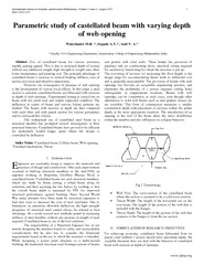
R Sagade AV Auti V Faculty Civil Engineering Department Amrutvahini College of Engineering Maharashtra India Abstract Use of castellated beam fo r various str uctures rapidly gaining appeal This is due to increased depth of section without any addit ID: 65723

Sagade Auti

Share:

Link:

Embed:

Download Presentation from below link

Download Pdf The PPT/PDF document "International Journal of Scientific and ..." is the property of its rightful owner. Permission is granted to download and print the materials on this web site for personal, non-commercial use only, and to display it on your personal computer provided you do not modify the materials and that you retain all copyright notices contained in the materials. By downloading content from our website, you accept the terms of this agreement.


Presentation Transcript

International Journal of Scientific and Research Publications , Volume 2, Issue 8, August 2012 1 ISSN 2250 - 3153 www.ijsrp.org Parametric study of castellated beam with varying depth of web opening Wakchaure M.R. * , Sagade A.V. * , Auti V . A . * * Faculty, Civil Engineering Department, Amrutvahini College of Engineering, Maharashtra, India . Abstract - Use of castellated beam fo r various str uctures rapidly gaining appeal. This is due to increased depth of section without any additional weight, high strength to weight ratio, their lower maintenance and painting cost. Th e principle advantage of castellated beam is increase in verti cal bending stiffness, ease of service provision and attractive appearance. However one consequence of presence of web opening is the development of various local effects. In this paper a steel section is selected, castellated beams are fabricated with inc rease in depth of web openings. Experimental testing is carried out on beam with two point load and simply supported condition. The deflection at centre of beam and various failure patterns are studied. The beams with increase in depth are then compared wi th each other and with parent section for various parameters and for serviceability criteria. The widespread use of castellated steel beam as a structural member has prompted several investigation in their structural behavior. Castellated beams have prov ed to be efficient for moderately loaded longer spans where the design is controlled by deflection. Index Terms - C astellated beam, Cellular beam, Web opening, Virendeel mechanism , Throat I. I NTRODUCTION ngineers are constantly trying to improve the materials and practices of design and construction. One such improvement occurred in built - up structural members in the mid - 1930 , an engineer working in Argentina, Geoffrey Murray Boyd, is castellated beam. Castellated beams are such structural members, w hich are made by flame cutting a rolled beam along its centerline and then rejoining the two halves by welding so that the overall beam depth is increased by 50% for improved structural performance against bending. Since Second World War many attempts have been made by structural engineers to find new ways to decrease the cost of steel structures. Due to limitations on minimum allowable deflection, the high strength properties of structural steel cannot always be utilized to best advantage. As a result seve ral new methods aimed at increasing stiffness of steel member, without any increase in weight of steel required. C astellated beam is one of the best solutions. The responsibility of a Structural Engineer lies in not merely designing the structure based on safety and serviceability considerations but he also has to consider the functional requirements based on the use to which the structure is intended. While designing a power plant structure or a multi - storied building, the traditional structural steel fra ming consists of beams and girders with solid webs. These hinder the provision of pipelines and air conditioning ducts, electrical wiring required for satisfactory functioning for which the structure is put up. The re - routing of services (or increasing the floor height at the design stage for accommodating them) leads to additional cost and is generally unacceptable. The provision of beams with web openings has become an acceptable engineering practice, and eliminates the probability of a service engineer c utting holes subsequently in inappropriate locations. Beams with web openings can be competitive in such cases, even though other alternatives to solid web beams such as stub girders, trusses etc are available. This form of construction maintains a smaller construction depth with placement of services within the girder depth, at the most appropriate locations. The introduction of an opening in the web of the beam alters the stress distribution within the member and also influences its collapse behavior. Fig.1 Terminology  Web Post: The cross - section of the castellated beam where the section is assumed to be a solid cross - section.  Throat Width: The length of the horizontal cut on the root beam. The length of the portion of the web that is included with the flanges.  Throat Depth: The height of the portion of the web that connects to the flanges to form the tee section. II. FORM ULATION OF RESEARCH OBJECTIVES For achieving economy, castellated beam fabricated fr om its parent solid webbed I section should have maximum depth . An available literature does n ot deal with the behavior of castellated beam with increase in depth of openings. E International Journal of Scientific and Research Publications , Volume 2, Issue 8, August 2012 2 ISSN 2250 - 3153 www.ijsrp.org This paper investigates the effect of web openings on various structural aspects of castellated beam, various modes of failures, and effect on deflection with increase in the depth of web openings . Depth of beam increased in processes of castellation by 40, 50 and 60%, with hexagonal shape o penings of angle 60 0 . width, since the castellated beams are relatively slender and have w eb openings, which have an influence on their resistance. The major failure modes of castellated beams are web post buckling [2] - [3] and lateral - torsional buckling. The failure modes mainly depend on area of openings, location of opening, length of the tee - section above and below the opening, opening depth and type of opening, type of loading. The experimental testing on steel beams with web opening of various shapes and sizes is conducted . Six potential failure modes [1] associated with castellated be ams are - A. Formation of Flexure Mechanism This mode of failure can occur when a section is subject to pure bending. The span subjected to pure bending moment, the tee - sections above and below the holes yielded in a manner similar to that of a plain webbed beam, although the spread of yield towards the central axis was stopped by the presence of the holes by which time the two throat sections had become completely plastic in compression and in tension. B. Lateral - Torsional Buckling Non - composite castellate d beams are more susceptible to lateral - torsional buckling than composite beams due to lack of lateral support to the compression flange. The lateral torsional buckling behaviour of castellated beams is similar to that of plain webbed beams. The holes had a significant influence on lateral - torsional buckling behavior . C. Formation of Vierendeel Mechanism Vierendeel bending is caused by the need to transfer the shear force across the opening to be consistent wi th the rate of change of bending moment, in the absence of local or overall instability, hexagonal castellated beams have two basic modes of plastic collapse, depending on the opening geometry. The failure is dependent on the presence of a shear force of high magnitude in the holes through span. D. Rupture of the Welded Joint in a Web Post Rupture of a welded joint in a web - post can result when the width of the web - post or length of welded joint is small. This mode of failure is caused by the action of the horizontal shearing force in the web - post, which is needed to balance the shear forces applied at the points of contra flexure at the ends of the upper I - section. E. Shear Bucking of a Web Post The horizontal shear force in the web - po st is associated with double curvature bending over the height of the post. In castellated beam one inclined edge of the opening will be stressed in tension, and the opposite edge in compression and buckling will cause a twisting effect of the web post al ong its height. III. EXPERIMENTAL TESTING ISMB150 is selected as a parent section for fabricating castellated beam. Following guidelines are followed for fabrication - · The hole should be centrally placed in the web and eccentricity of the opening is avoided as far as possible. · Stiffened openings are not always appropriate, unless they are located in low shear and low bending moment regions. · Web opening should be away from the support by at least twice the beam depth, D or 10% of the span, whichever is greate r. · The best location for the opening is within the middle third of the span. · Clear Spacing between the openings should not be less than beam depth D. · The best location for opening is where the shear force is the lowest. · The diameter of circular openings is generally restricted to 0.5D. · Depth of rectangular openings should not be greater than 0.5D and the length not greater than 1.5D for un - stiffened openings. · The clear spacing between such openings should be at least equal the longer dimension of the openin g. · The depth of the rectangular openings should not be greater than 0.6D and the length not greater than 2D for stiffened openings. The above rule regarding spacing applies. · Corners of rectangular openings should be rounded. · Point loads should not be appli ed at less than D from side of the adjacent opening. · If stiffeners are provided at the openings, the length of the welds should be sufficient to devel op the full strength of the stiffener. · If the above rules are followed, the additional deflection due to each opening may be taken as 3% of the mid - span deflection of the beam without the opening. Fig . 2 Mathematical Formulation of Castellated Beam International Journal of Scientific and Research Publications , Volume 2, Issue 8, August 2012 3 ISSN 2250 - 3153 www.ijsrp.org F ig.3 Beam Ic 210mm is Mounted of UTM for Testing Fig.4 Local Failure Mode – Buckling of Compression Flange Fig.5 Web Buckling of Beam Ic 225mm Fig.6 Stress Concentration in Ic 225 at Hole Corner Fig.7 Flexure Buckling of Beam Ic 240 Fig. 8 Failure of Beam Ic 240 In Flexure International Journal of Scientific and Research Publications , Volume 2, Issue 8, August 2012 4 ISSN 2250 - 3153 www.ijsrp.org Fig.9 Local Failure - Vierendeel Effect (Stress Concentration at Hole Corners of IC 240) Fig.10 Testing Arrangement for Solid Web Beam ISMB 150 Fig.11 Local Fai lure - Failure of Compression Flange ISMB 150 Fig.12 Lateral Torsional Buckling of ISMB 150 IV. RESULT S Table I : Load v/s D eflection for ISMB150 Table II : Load v/s Deflection for Ic 210 Sr . No . Load (kN) Deflection (mm) 1 0 .00 0 .00 2 10.38 1 .00 3 20.38 1.7 0 4 30.38 2.54 5 40.38 3.45 6 50.38 4.5 0 7 60.38 5.4 0 8 70.38 6.42 9 80.38 7.32 10 90.38 8.55 11 94.38 9.45 12 96.38 10.54 Sr. No. Load ( kN) Deflection (mm) 1 0 .00 0 .00 2 10.38 0.82 3 20.38 1.5 0 4 30.38 2.6 0 5 40.38 3.5 4 6 50.38 4.4 0 7 60.38 5.5 0 8 70.38 6.25 9 80.38 7.15 10 90.38 8 .00 11 100.38 9.3 0 12 110.38 12.35 13 112.38 18.58 International Journal of Scientific and Research Publications , Volume 2, Issue 8, August 2012 5 ISSN 2250 - 3153 www.ijsrp.org Table III : Load v/s Deflection fo r Ic 225 Table IV : Load v/s Deflection for Ic240 Graph.1 Load v/s Deflection for ISMB 150 by Tes ting Graph.2 Load v/s Deflect ion for Ic 210 by Testing Graph.3 Load v/s Deflection for Ic 225 by Testing Graph.4 Load v/s Deflection for Ic 240 by Testing Sr . N o . Load ( kN) Deflection (mm) 1 0 .00 0 .00 2 10.38 0.9 0 3 20.38 1.7 0 4 30.38 2.56 5 40.38 3.48 6 50.38 4.55 7 60.38 5.56 8 70.38 6.87 9 80.38 9.22 10 90.38 12.6 11 94.38 13.93 Sr No Load (kN) Deflection (mm) 1 0 .00 0 .00 2 10.38 0.72 3 20.38 1.61 4 30.38 2.55 5 40.38 3.48 6 50.38 4.5 0 7 60.38 5.81 8 70.38 8.72 9 80.38 16 .00 10 84.38 20.76 International Journal of Scientific and Research Publications , Volume 2, Issue 8, August 2012 6 ISSN 2250 - 3153 www.ijsrp.org Graph.5 Comparison of All Beam for Load v/s Deflection Serviceability limit for beam= L/325 =1900/325 =5.846mm W e can compare them for Serviceability limi t, and the results are TableV: Comparison of results for serviceability limit This indicates that up to the serviceability limit cast ellated beams has nearly same stiffness of its parent beam. After this load increased continuously, due to presence of holes in the web opening it starts introducing some local effect, due to which its deflection increases rapidly and moment carrying capac ity decreases. It also shows that beams castellated for 0.4D, 0.5D are showing good results where as beam castellated with 0.6D shows averaged result, that indicate some corrective measures should be taken to avoid this. For carrying maximum moment we have to follow following conditions while designing: · To avoid local failure of beam. (i.e. provision of plate below concentrated load). · To provide reinforcement at the weak sections of the beam. · To avoid Vierendeel effect (to avoid stress concentration) corner s of the holes are to be rounded. V CONCLUSION S From the experimen tal testing, it is concluded that, Castellated steel beam behaves satisfactory for serviceability, up to maximum depth of opening 0.6D. Castellated beams has holes in its web, a s holes incorporated various local effects in beams, increase in load causes beams to be failed in different failure mode, which resist them to take load up to their actual carrying capacity. So we cannot compare beams with different modes of failure direc tly for strength criteria. Due to the presence of holes in the web, the structural behavior of castellated st eel beam will be different from that of the solid web beams . It make structure highly indeterminate, which may not analyzed by simple methods of analysis. So we have to design beam to avoid local effects, for improved performance of castellated beam. It is observed as depth of opening increases in Vierendeel effects is prominently observed at the hole corners, so by taking corrective measures (i.e corners should be rounded , provision of reinforcement) we can expect improvement in performance of beam. We c an conclude that castellated beams are well accepted for industrial buildings, power plant and multistoried structures, where generally loads are less and spans are more with its economy and satisfying serviceability criteria. R EFERENCES [1] J. P. BOYER “Cast ellated Beam - A New Development” ( AISC National Engineering Conference, Omaha, Nebr., in May, 1964) [2] Richard Redwoodland Sevak Demirdjian “Castellated Beam Web Buckling In Shear” Journal of Structural Engineering 1 october 1998/1207 [3] Walid Zaaroue and Richard Redwood “Web Buckling In Thin Webbed Castellated Beams” Journal Of Structural Engineering I August 1996/8661 [4] H. R. Kazemi Nia Korrani1, M. Z. Kabir, S. Molanaei “ Lateral - Torsional Buckling of Castellated Beams Under End Moments” (International J. of Recen t Trends in Engineering and Technology, Vol. 3, No. 5, May 2010 ) [5] Tadeh Zirakian, Hossein Showkati “ Distortional Buckling of Castellated Beams” (Journal of Constructional Steel Research 62 (2006) 863 – 871). [6] By Ehab Ellobody “Nonlinear Analysis of Cellulars Steel Beams Under Combined Buckling Modes” (Thin - Walled Structures 52 (2012) 66 – 79). [7] Nikos D. Lagaros, Lemonis D. Psarras, Manolis Papadrakakis, Giannis Panagiotou “Optimum Design of Steel Structures with Web Openings” (Engineering Structures 30 (2008) 2 528 – 2537) A UTHORS First Author – Wakchaure M.R. * , ME Structures, Faculty, Civil Engineering Department, Amrutvahini College of Engineering, Sangamner, Maharashtra , India Second Author – Sagade A.V. * , ME Structures, Faculty, Civil Engineering Departmen t, Amrutvahini College of Engineering, Sangamner, Maharashtra, India .EMAIL:aparna.sagade@gmail.com Third Author – Auti V . A . * , ME (W.M.), Faculty, Civil Engineering Department, Amrutvahini College of Engineering, Sangamner, Maharashtra, India. Sr. No Beam Defle ction ( mm ) Max load ( kN ) Local Mode Of Failure Global Mode 1 ISMB 150 5.86 78 Failure of compression flange Lateral torsional buckling 2 Ic 210 72 Failure of compression flange Flexural buckling of Web 3 Ic 225 68 Failure of compression flange and Vierendeel effect Web buckling 4 Ic 240 62 Vierendeel effect and Failure of compression flange Flexural buckling of Web