
1 3.1 Control valves In a hydraulic system, the
FD
Published · 21 slides · 0 views

1 / 1
Description
1 3.1 Control valves In a hydraulic system, the hydraulic energy available from a pump is converted into motion and force by means of an actuator. The control of these mechanical outputs (motion and force) is one of the most important
Related Topics
Share
Embed code
Download this presentation From Below
"1 3.1 Control valves In a hydraulic system, the" is the property of its rightful owner. Permission is granted to download and print the materials on this website for personal, non-commercial use only, and to display it on your personal computer provided you do not modify the materials and that you retain all copyright notices contained in the materials. By downloading content from our website, you accept the terms of this agreement.
Presentation Transcript
01
1 3.1 Control valves In a hydraulic system, the hydraulic energy available from a pump is converted into motion
and force by means of an actuator. The control of these mechanical outputs (motion and force)
is one of the most important function in a hydraulic system. The proper selection of control selection ensures the desired output and safe function of the system. In order to control the
hydraulic outputs, different types of control valves are required. It is important to know various
types of control valves and their functions. This not only helps to design a proper hydraulic
system but also helps to discover the innovative ways to improve the existing systems. There are basically three types of valves employed in hydraulic systems: • Directional control valve s • Flow control valves • Pressure control valves 3.2 Direction control valve Directional control valves are used to control the distribution of energy in a fluid power system. They provide the direction to the fluid and allow the flow in a particular direction. These valves
are used to control the start, stop and change in direction of the fluid flow. These valves regulate
the flow direction in the hydraulic circuit. These control valves contain ports that are external
openings for the fluid to enter and leave. The number of ports is usually identified by the term ‘way'. For example, a valve with four ports is named as four-way valve. The fluid flow rate is
responsible for the speed of actuator (motion of the output) and should controlled in a hydraulic
system. This operation can be performed by using flow control valves. The pressure may
increase gradually when the system is under operation. The pressure control valves protect the system by maintaining the system pressure within the desired range. Also, the output force is
directly proportional to the pressure and hence, the pressure control valves ensure the desired
force output at the actuator. Directional control valves can be classified in the following manner: 1. Type of construction:
2. Number of ports
3. Number of switching position.
4. Actuating mechanism. 3.2.1 Type of construction There are two basic control elements used in hydraulic control valves • Poppet valves • Spool valves Table 3.1 shows the construction of both types<br>
and force by means of an actuator. The control of these mechanical outputs (motion and force)
is one of the most important function in a hydraulic system. The proper selection of control selection ensures the desired output and safe function of the system. In order to control the
hydraulic outputs, different types of control valves are required. It is important to know various
types of control valves and their functions. This not only helps to design a proper hydraulic
system but also helps to discover the innovative ways to improve the existing systems. There are basically three types of valves employed in hydraulic systems: • Directional control valve s • Flow control valves • Pressure control valves 3.2 Direction control valve Directional control valves are used to control the distribution of energy in a fluid power system. They provide the direction to the fluid and allow the flow in a particular direction. These valves
are used to control the start, stop and change in direction of the fluid flow. These valves regulate
the flow direction in the hydraulic circuit. These control valves contain ports that are external
openings for the fluid to enter and leave. The number of ports is usually identified by the term ‘way'. For example, a valve with four ports is named as four-way valve. The fluid flow rate is
responsible for the speed of actuator (motion of the output) and should controlled in a hydraulic
system. This operation can be performed by using flow control valves. The pressure may
increase gradually when the system is under operation. The pressure control valves protect the system by maintaining the system pressure within the desired range. Also, the output force is
directly proportional to the pressure and hence, the pressure control valves ensure the desired
force output at the actuator. Directional control valves can be classified in the following manner: 1. Type of construction:
2. Number of ports
3. Number of switching position.
4. Actuating mechanism. 3.2.1 Type of construction There are two basic control elements used in hydraulic control valves • Poppet valves • Spool valves Table 3.1 shows the construction of both types<br>
02
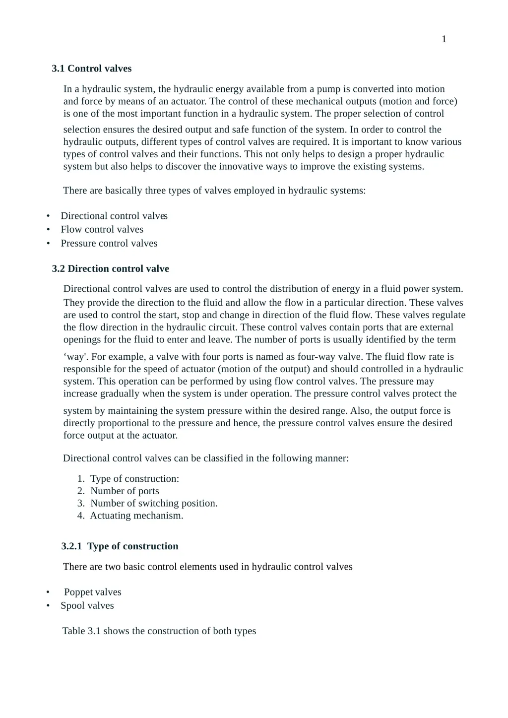
2 Table 3.1 Basic Constructional Elements of Hydraulic Control Valves An example of poppet valve is: 3.2.1.1 Check valves These are unidirectional valves and permit the free flow in one direction only. These valves
have two ports: one for the entry of fluid and the other for the discharge. They are consisting
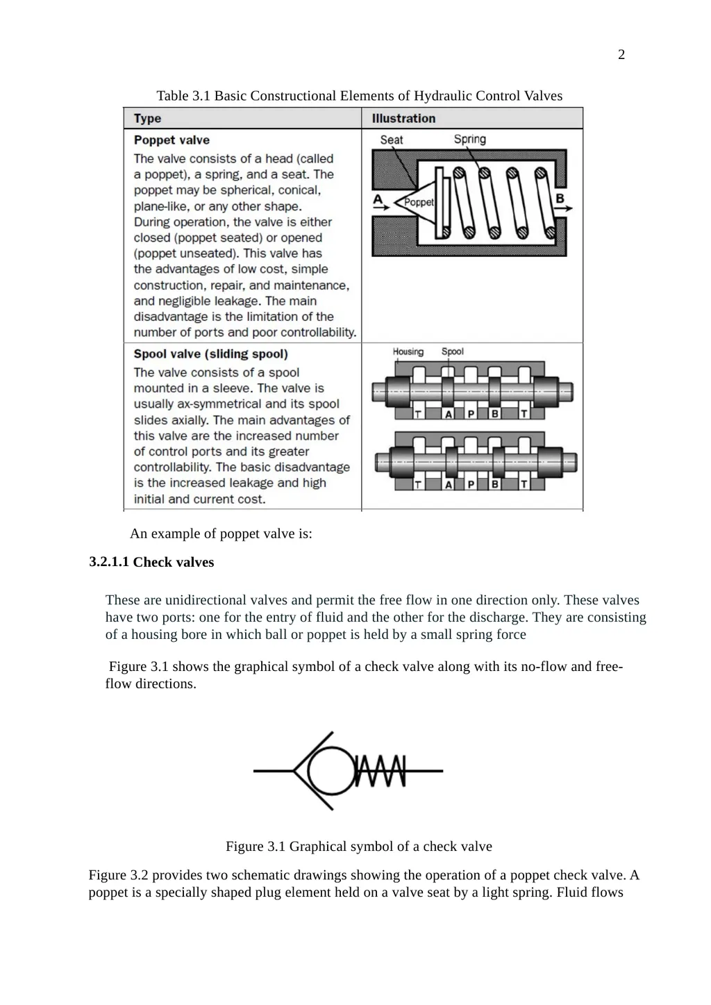
of a housing bore in which ball or poppet is held by a small spring force Figure 3.1 shows the graphical symbol of a check valve along with its no-flow and free-
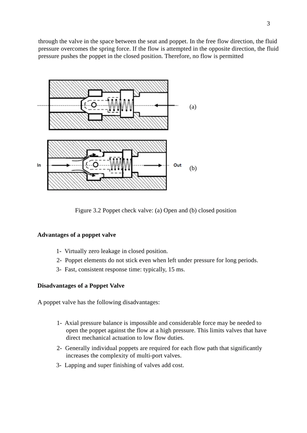
flow directions. Figure 3.1 Graphical symbol of a check valve Figure 3.2 provides two schematic drawings showing the operation of a poppet check valve. A
poppet is a specially shaped plug element held on a valve seat by a light spring. Fluid flows<br>
have two ports: one for the entry of fluid and the other for the discharge. They are consisting
of a housing bore in which ball or poppet is held by a small spring force Figure 3.1 shows the graphical symbol of a check valve along with its no-flow and free-
flow directions. Figure 3.1 Graphical symbol of a check valve Figure 3.2 provides two schematic drawings showing the operation of a poppet check valve. A
poppet is a specially shaped plug element held on a valve seat by a light spring. Fluid flows<br>
03
3 through the valve in the space between the seat and poppet. In the free flow direction, the fluid
pressure overcomes the spring force. If the flow is attempted in the opposite direction, the fluid
pressure pushes the poppet in the closed position. Therefore, no flow is permitted (a) (b) Figure 3.2 Poppet check valve: (a) Open and (b) closed position Advantages of a poppet valve 1- Virtually zero leakage in closed position. 2- Poppet elements do not stick even when left under pressure for long periods. 3- Fast, consistent response time: typically, 15 ms. Disadvantages of a Poppet Valve A poppet valve has the following disadvantages: 1- Axial pressure balance is impossible and considerable force may be needed to
open the poppet against the flow at a high pressure. This limits valves that have
direct mechanical actuation to low flow duties. 2- Generally individual poppets are required for each flow path that significantly
increases the complexity of multi-port valves. 3- Lapping and super finishing of valves add cost.<br>
pressure overcomes the spring force. If the flow is attempted in the opposite direction, the fluid
pressure pushes the poppet in the closed position. Therefore, no flow is permitted (a) (b) Figure 3.2 Poppet check valve: (a) Open and (b) closed position Advantages of a poppet valve 1- Virtually zero leakage in closed position. 2- Poppet elements do not stick even when left under pressure for long periods. 3- Fast, consistent response time: typically, 15 ms. Disadvantages of a Poppet Valve A poppet valve has the following disadvantages: 1- Axial pressure balance is impossible and considerable force may be needed to
open the poppet against the flow at a high pressure. This limits valves that have
direct mechanical actuation to low flow duties. 2- Generally individual poppets are required for each flow path that significantly
increases the complexity of multi-port valves. 3- Lapping and super finishing of valves add cost.<br>
04
4 3.2.1.2 Spool valve The spool valves derive their name from their appearance. It consists of a shaft sliding in a bore
which has large groove around the circumference. This type of construction makes it look like
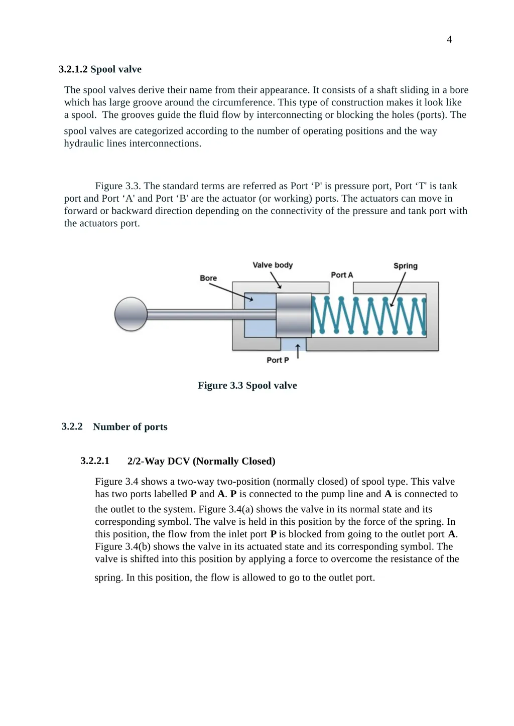
a spool. The grooves guide the fluid flow by interconnecting or blocking the holes (ports). The spool valves are categorized according to the number of operating positions and the way
hydraulic lines interconnections. Figure 3.3. The standard terms are referred as Port ‘P' is pressure port, Port ‘T' is tank
port and Port ‘A' and Port ‘B' are the actuator (or working) ports. The actuators can move in
forward or backward direction depending on the connectivity of the pressure and tank port with
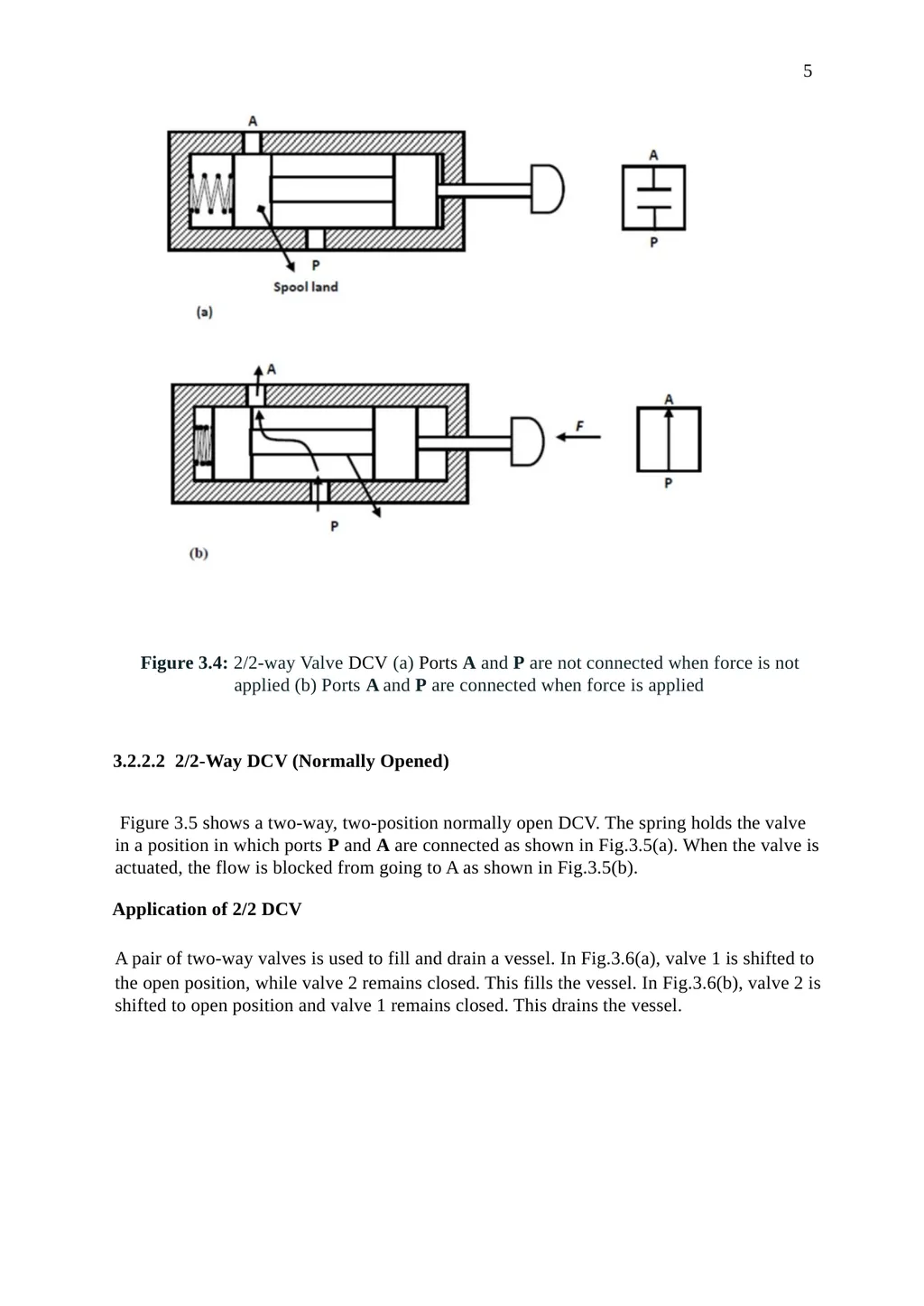
the actuators port. Figure 3.3 Spool valve 3.2.2 Number of ports 3.2.2.1 2/2-Way DCV (Normally Closed) Figure 3.4 shows a two-way two-position (normally closed) of spool type. This valve
has two ports labelled P and A. P is connected to the pump line and A is connected to the outlet to the system. Figure 3.4(a) shows the valve in its normal state and its
corresponding symbol. The valve is held in this position by the force of the spring. In
this position, the flow from the inlet port P is blocked from going to the outlet port A.
Figure 3.4(b) shows the valve in its actuated state and its corresponding symbol. The
valve is shifted into this position by applying a force to overcome the resistance of the spring. In this position, the flow is allowed to go to the outlet port.<br>
which has large groove around the circumference. This type of construction makes it look like
a spool. The grooves guide the fluid flow by interconnecting or blocking the holes (ports). The spool valves are categorized according to the number of operating positions and the way
hydraulic lines interconnections. Figure 3.3. The standard terms are referred as Port ‘P' is pressure port, Port ‘T' is tank
port and Port ‘A' and Port ‘B' are the actuator (or working) ports. The actuators can move in
forward or backward direction depending on the connectivity of the pressure and tank port with
the actuators port. Figure 3.3 Spool valve 3.2.2 Number of ports 3.2.2.1 2/2-Way DCV (Normally Closed) Figure 3.4 shows a two-way two-position (normally closed) of spool type. This valve
has two ports labelled P and A. P is connected to the pump line and A is connected to the outlet to the system. Figure 3.4(a) shows the valve in its normal state and its
corresponding symbol. The valve is held in this position by the force of the spring. In
this position, the flow from the inlet port P is blocked from going to the outlet port A.
Figure 3.4(b) shows the valve in its actuated state and its corresponding symbol. The
valve is shifted into this position by applying a force to overcome the resistance of the spring. In this position, the flow is allowed to go to the outlet port.<br>
05
5 Figure 3.4: 2/2-way Valve DCV (a) Ports A and P are not connected when force is not
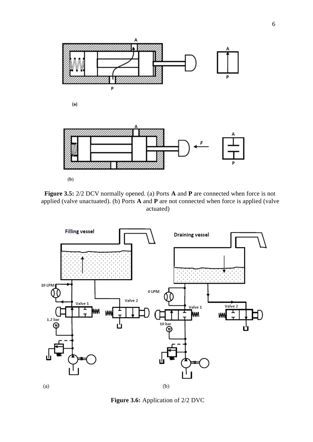
applied (b) Ports A and P are connected when force is applied 3.2.2.2 2/2-Way DCV (Normally Opened) Figure 3.5 shows a two-way, two-position normally open DCV. The spring holds the valve
in a position in which ports P and A are connected as shown in Fig.3.5(a). When the valve is
actuated, the flow is blocked from going to A as shown in Fig.3.5(b). Application of 2/2 DCV A pair of two-way valves is used to fill and drain a vessel. In Fig.3.6(a), valve 1 is shifted to the open position, while valve 2 remains closed. This fills the vessel. In Fig.3.6(b), valve 2 is
shifted to open position and valve 1 remains closed. This drains the vessel.<br>
applied (b) Ports A and P are connected when force is applied 3.2.2.2 2/2-Way DCV (Normally Opened) Figure 3.5 shows a two-way, two-position normally open DCV. The spring holds the valve
in a position in which ports P and A are connected as shown in Fig.3.5(a). When the valve is
actuated, the flow is blocked from going to A as shown in Fig.3.5(b). Application of 2/2 DCV A pair of two-way valves is used to fill and drain a vessel. In Fig.3.6(a), valve 1 is shifted to the open position, while valve 2 remains closed. This fills the vessel. In Fig.3.6(b), valve 2 is
shifted to open position and valve 1 remains closed. This drains the vessel.<br>
06
6 Figure 3.5: 2/2 DCV normally opened. (a) Ports A and P are connected when force is not
applied (valve unactuated). (b) Ports A and P are not connected when force is applied (valve
actuated) Figure 3.6: Application of 2/2 DVC<br>
applied (valve unactuated). (b) Ports A and P are not connected when force is applied (valve
actuated) Figure 3.6: Application of 2/2 DVC<br>
07
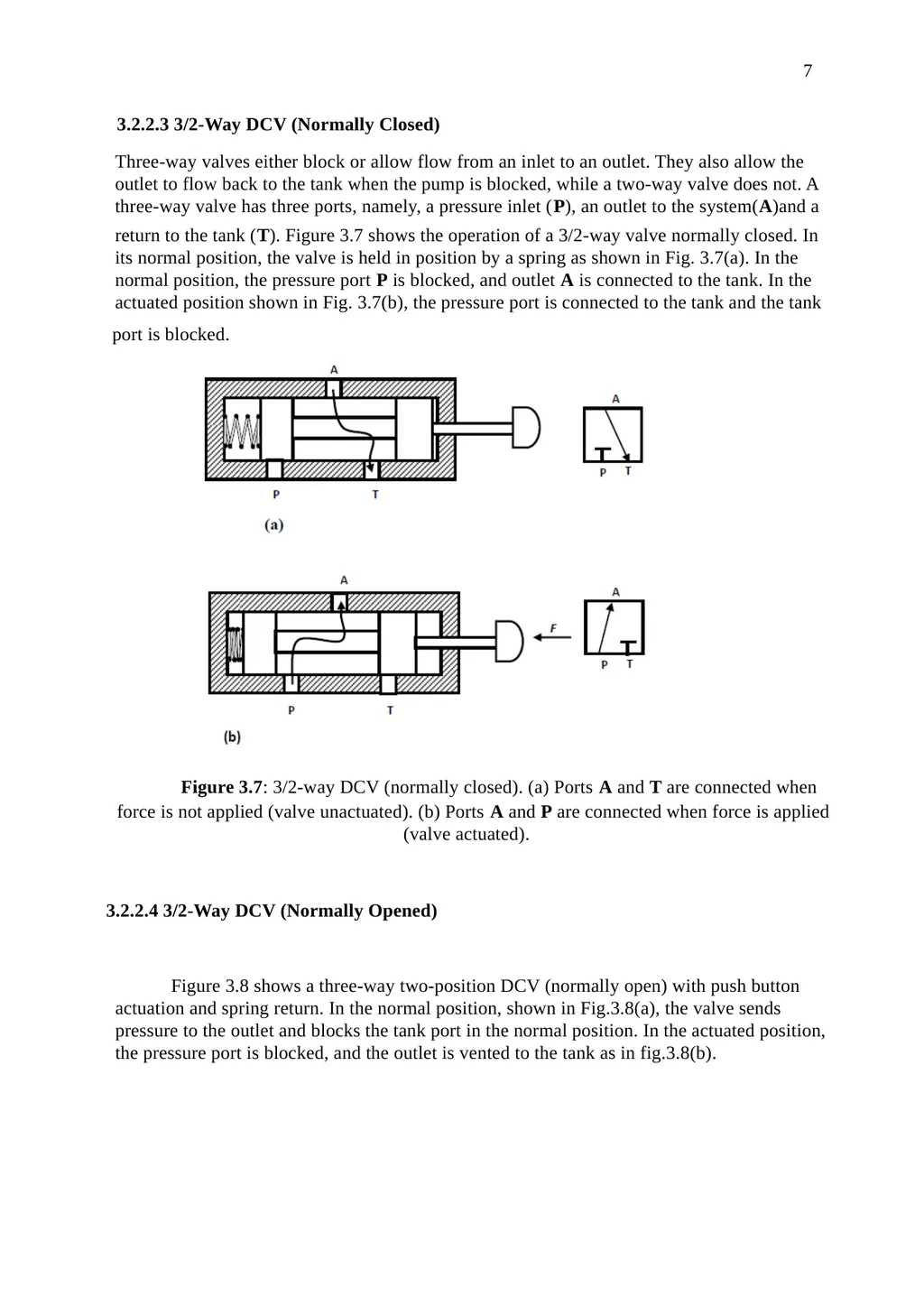
7 3.2.2.3 3/2-Way DCV (Normally Closed) Three-way valves either block or allow flow from an inlet to an outlet. They also allow the
outlet to flow back to the tank when the pump is blocked, while a two-way valve does not. A
three-way valve has three ports, namely, a pressure inlet (P), an outlet to the system(A)and a return to the tank (T). Figure 3.7 shows the operation of a 3/2-way valve normally closed. In
its normal position, the valve is held in position by a spring as shown in Fig. 3.7(a). In the
normal position, the pressure port P is blocked, and outlet A is connected to the tank. In the
actuated position shown in Fig. 3.7(b), the pressure port is connected to the tank and the tank port is blocked. Figure 3.7: 3/2-way DCV (normally closed). (a) Ports A and T are connected when force is not applied (valve unactuated). (b) Ports A and P are connected when force is applied
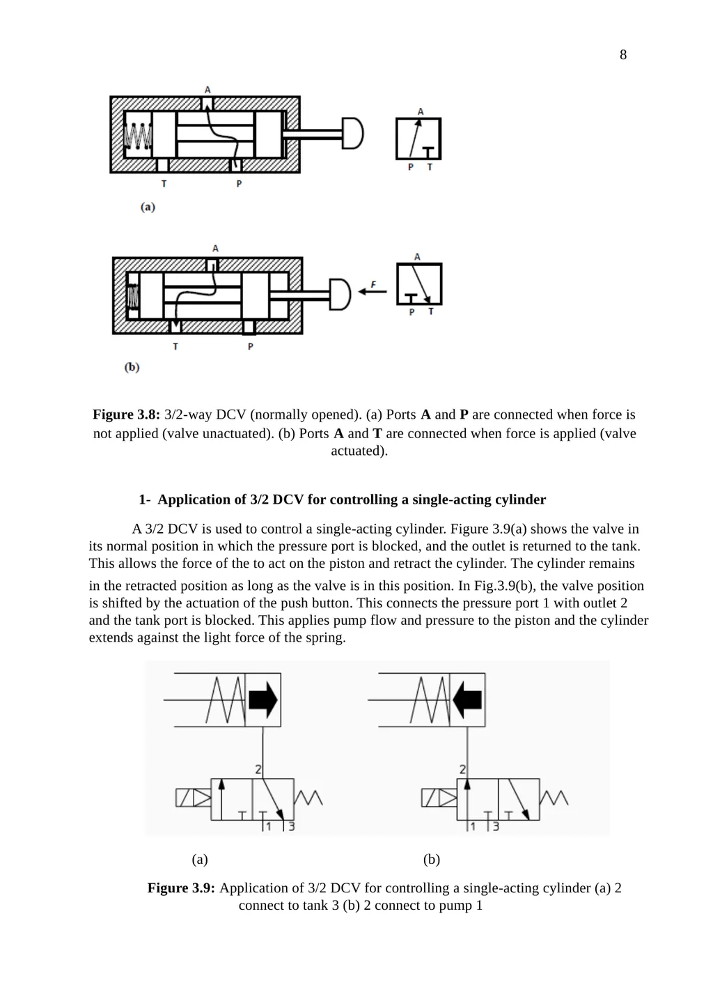
(valve actuated). 3.2.2.4 3/2-Way DCV (Normally Opened) Figure 3.8 shows a three-way two-position DCV (normally open) with push button
actuation and spring return. In the normal position, shown in Fig.3.8(a), the valve sends
pressure to the outlet and blocks the tank port in the normal position. In the actuated position,
the pressure port is blocked, and the outlet is vented to the tank as in fig.3.8(b).<br>
outlet to flow back to the tank when the pump is blocked, while a two-way valve does not. A
three-way valve has three ports, namely, a pressure inlet (P), an outlet to the system(A)and a return to the tank (T). Figure 3.7 shows the operation of a 3/2-way valve normally closed. In
its normal position, the valve is held in position by a spring as shown in Fig. 3.7(a). In the
normal position, the pressure port P is blocked, and outlet A is connected to the tank. In the
actuated position shown in Fig. 3.7(b), the pressure port is connected to the tank and the tank port is blocked. Figure 3.7: 3/2-way DCV (normally closed). (a) Ports A and T are connected when force is not applied (valve unactuated). (b) Ports A and P are connected when force is applied
(valve actuated). 3.2.2.4 3/2-Way DCV (Normally Opened) Figure 3.8 shows a three-way two-position DCV (normally open) with push button
actuation and spring return. In the normal position, shown in Fig.3.8(a), the valve sends
pressure to the outlet and blocks the tank port in the normal position. In the actuated position,
the pressure port is blocked, and the outlet is vented to the tank as in fig.3.8(b).<br>
08
8 Figure 3.8: 3/2-way DCV (normally opened). (a) Ports A and P are connected when force is not applied (valve unactuated). (b) Ports A and T are connected when force is applied (valve
actuated). 1- Application of 3/2 DCV for controlling a single-acting cylinder A 3/2 DCV is used to control a single-acting cylinder. Figure 3.9(a) shows the valve in
its normal position in which the pressure port is blocked, and the outlet is returned to the tank.
This allows the force of the to act on the piston and retract the cylinder. The cylinder remains in the retracted position as long as the valve is in this position. In Fig.3.9(b), the valve position
is shifted by the actuation of the push button. This connects the pressure port 1 with outlet 2
and the tank port is blocked. This applies pump flow and pressure to the piston and the cylinder
extends against the light force of the spring. (a) (b) Figure 3.9: Application of 3/2 DCV for controlling a single-acting cylinder (a) 2
connect to tank 3 (b) 2 connect to pump 1<br>
actuated). 1- Application of 3/2 DCV for controlling a single-acting cylinder A 3/2 DCV is used to control a single-acting cylinder. Figure 3.9(a) shows the valve in
its normal position in which the pressure port is blocked, and the outlet is returned to the tank.
This allows the force of the to act on the piston and retract the cylinder. The cylinder remains in the retracted position as long as the valve is in this position. In Fig.3.9(b), the valve position
is shifted by the actuation of the push button. This connects the pressure port 1 with outlet 2
and the tank port is blocked. This applies pump flow and pressure to the piston and the cylinder
extends against the light force of the spring. (a) (b) Figure 3.9: Application of 3/2 DCV for controlling a single-acting cylinder (a) 2
connect to tank 3 (b) 2 connect to pump 1<br>
09
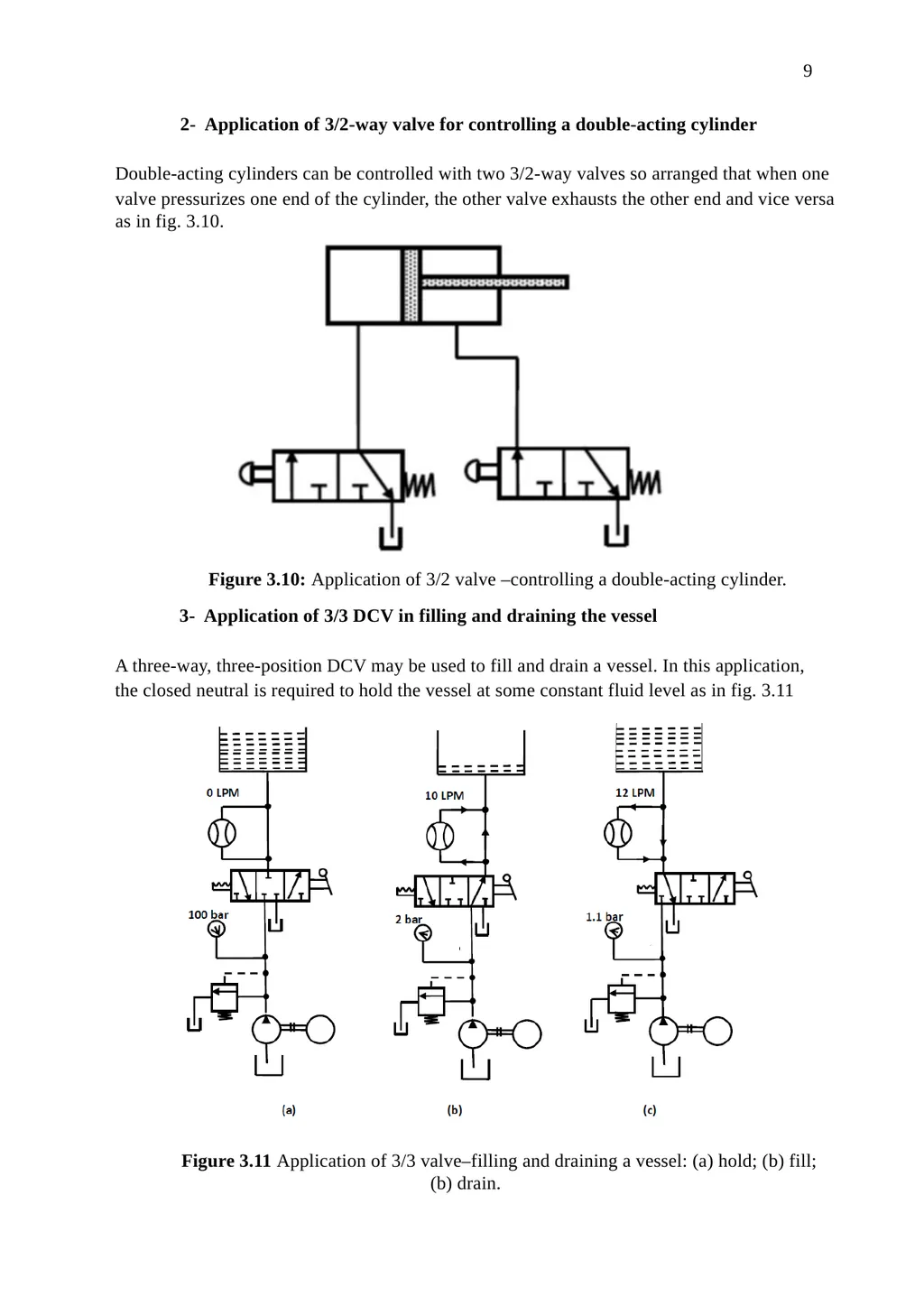
9 2- Application of 3/2-way valve for controlling a double-acting cylinder Double-acting cylinders can be controlled with two 3/2-way valves so arranged that when one valve pressurizes one end of the cylinder, the other valve exhausts the other end and vice versa
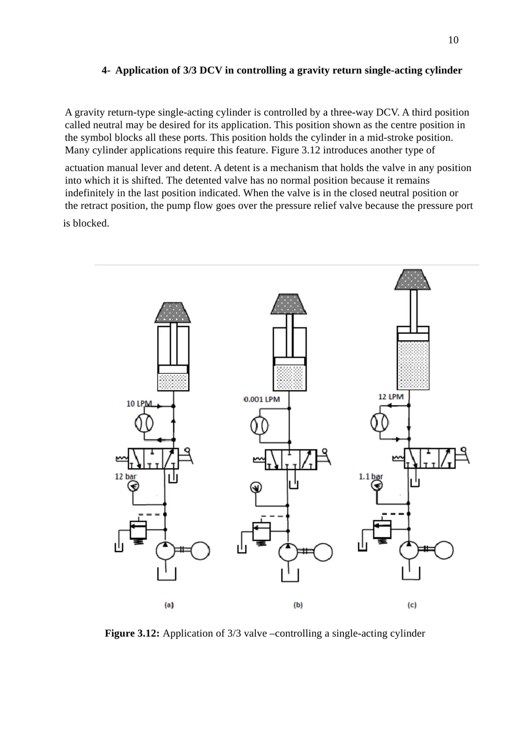
as in fig. 3.10. Figure 3.10: Application of 3/2 valve –controlling a double-acting cylinder. 3- Application of 3/3 DCV in filling and draining the vessel A three-way, three-position DCV may be used to fill and drain a vessel. In this application, the closed neutral is required to hold the vessel at some constant fluid level as in fig. 3.11 Figure 3.11 Application of 3/3 valve–filling and draining a vessel: (a) hold; (b) fill;
(b) drain.<br>
as in fig. 3.10. Figure 3.10: Application of 3/2 valve –controlling a double-acting cylinder. 3- Application of 3/3 DCV in filling and draining the vessel A three-way, three-position DCV may be used to fill and drain a vessel. In this application, the closed neutral is required to hold the vessel at some constant fluid level as in fig. 3.11 Figure 3.11 Application of 3/3 valve–filling and draining a vessel: (a) hold; (b) fill;
(b) drain.<br>
10
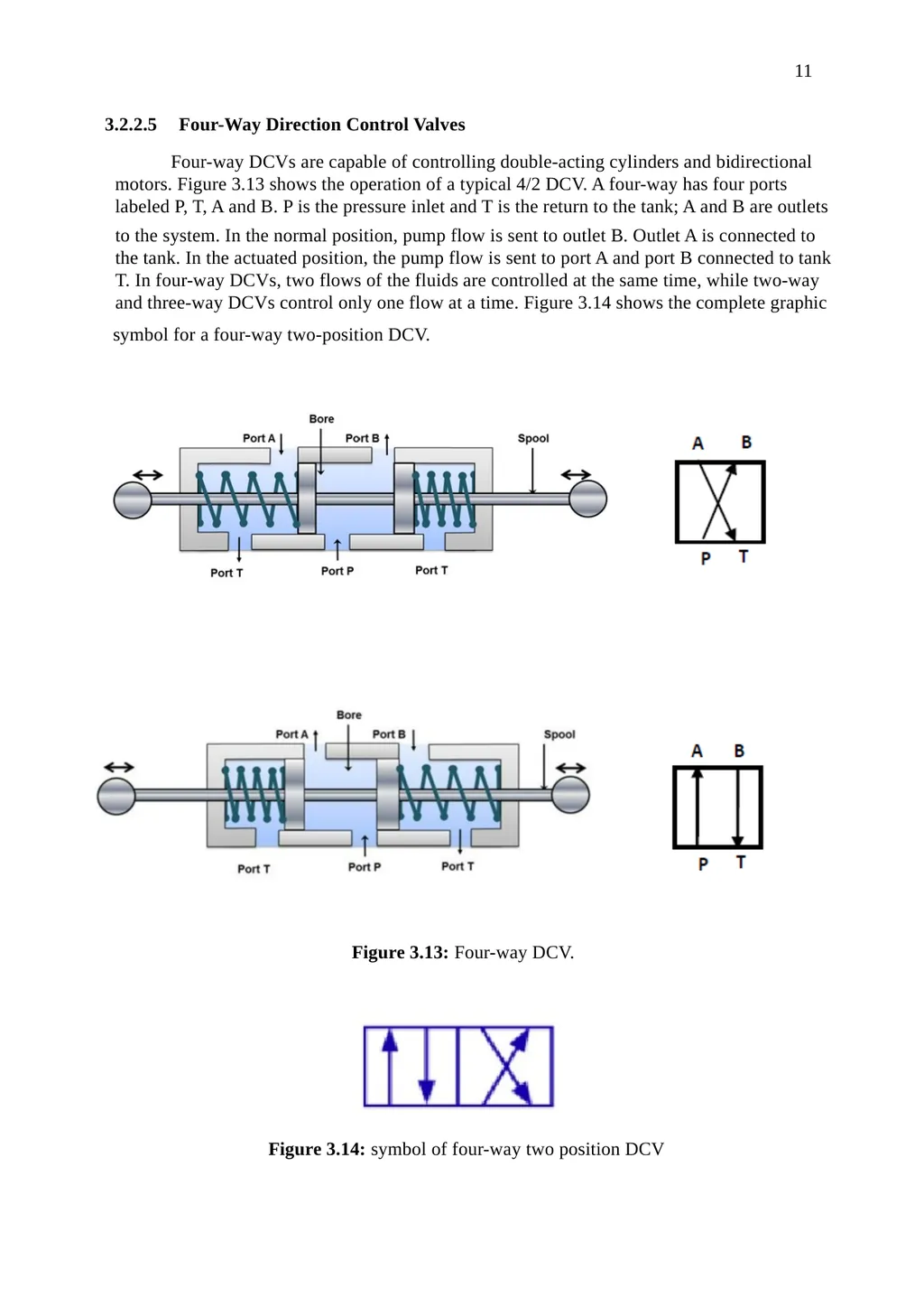
10 4- Application of 3/3 DCV in controlling a gravity return single-acting cylinder A gravity return-type single-acting cylinder is controlled by a three-way DCV. A third position
called neutral may be desired for its application. This position shown as the centre position in
the symbol blocks all these ports. This position holds the cylinder in a mid-stroke position.
Many cylinder applications require this feature. Figure 3.12 introduces another type of actuation manual lever and detent. A detent is a mechanism that holds the valve in any position
into which it is shifted. The detented valve has no normal position because it remains
indefinitely in the last position indicated. When the valve is in the closed neutral position or
the retract position, the pump flow goes over the pressure relief valve because the pressure port is blocked. Figure 3.12: Application of 3/3 valve –controlling a single-acting cylinder<br>
called neutral may be desired for its application. This position shown as the centre position in
the symbol blocks all these ports. This position holds the cylinder in a mid-stroke position.
Many cylinder applications require this feature. Figure 3.12 introduces another type of actuation manual lever and detent. A detent is a mechanism that holds the valve in any position
into which it is shifted. The detented valve has no normal position because it remains
indefinitely in the last position indicated. When the valve is in the closed neutral position or
the retract position, the pump flow goes over the pressure relief valve because the pressure port is blocked. Figure 3.12: Application of 3/3 valve –controlling a single-acting cylinder<br>
11
11 3.2.2.5 Four-Way Direction Control Valves Four-way DCVs are capable of controlling double-acting cylinders and bidirectional
motors. Figure 3.13 shows the operation of a typical 4/2 DCV. A four-way has four ports
labeled P, T, A and B. P is the pressure inlet and T is the return to the tank; A and B are outlets to the system. In the normal position, pump flow is sent to outlet B. Outlet A is connected to
the tank. In the actuated position, the pump flow is sent to port A and port B connected to tank
T. In four-way DCVs, two flows of the fluids are controlled at the same time, while two-way
and three-way DCVs control only one flow at a time. Figure 3.14 shows the complete graphic symbol for a four-way two-position DCV. Figure 3.13: Four-way DCV. Figure 3.14: symbol of four-way two position DCV<br>
motors. Figure 3.13 shows the operation of a typical 4/2 DCV. A four-way has four ports
labeled P, T, A and B. P is the pressure inlet and T is the return to the tank; A and B are outlets to the system. In the normal position, pump flow is sent to outlet B. Outlet A is connected to
the tank. In the actuated position, the pump flow is sent to port A and port B connected to tank
T. In four-way DCVs, two flows of the fluids are controlled at the same time, while two-way
and three-way DCVs control only one flow at a time. Figure 3.14 shows the complete graphic symbol for a four-way two-position DCV. Figure 3.13: Four-way DCV. Figure 3.14: symbol of four-way two position DCV<br>
12
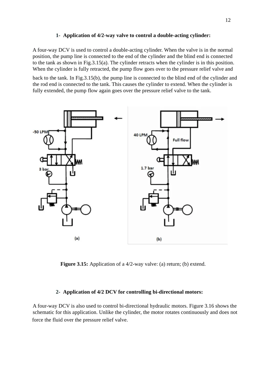
12 1- Application of 4/2-way valve to control a double-acting cylinder: A four-way DCV is used to control a double-acting cylinder. When the valve is in the normal
position, the pump line is connected to the end of the cylinder and the blind end is connected
to the tank as shown in Fig.3.15(a). The cylinder retracts when the cylinder is in this position.
When the cylinder is fully retracted, the pump flow goes over to the pressure relief valve and back to the tank. In Fig.3.15(b), the pump line is connected to the blind end of the cylinder and
the rod end is connected to the tank. This causes the cylinder to extend. When the cylinder is
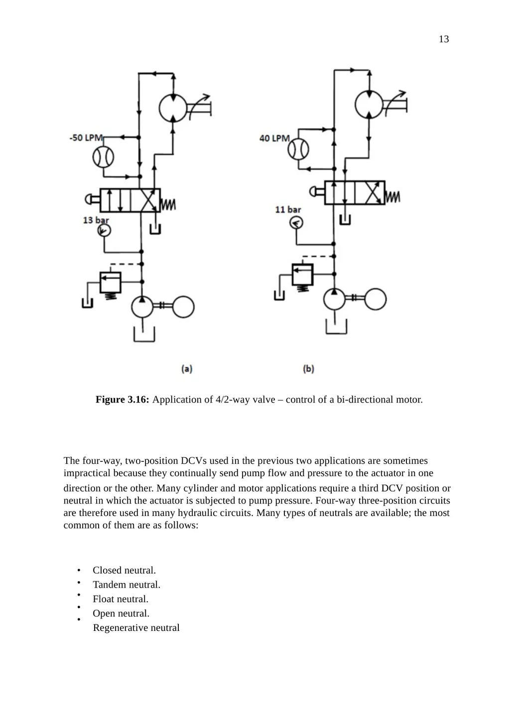
fully extended, the pump flow again goes over the pressure relief valve to the tank. Figure 3.15: Application of a 4/2-way valve: (a) return; (b) extend. 2- Application of 4/2 DCV for controlling bi-directional motors: A four-way DCV is also used to control bi-directional hydraulic motors. Figure 3.16 shows the
schematic for this application. Unlike the cylinder, the motor rotates continuously and does not force the fluid over the pressure relief valve.<br>
position, the pump line is connected to the end of the cylinder and the blind end is connected
to the tank as shown in Fig.3.15(a). The cylinder retracts when the cylinder is in this position.
When the cylinder is fully retracted, the pump flow goes over to the pressure relief valve and back to the tank. In Fig.3.15(b), the pump line is connected to the blind end of the cylinder and
the rod end is connected to the tank. This causes the cylinder to extend. When the cylinder is
fully extended, the pump flow again goes over the pressure relief valve to the tank. Figure 3.15: Application of a 4/2-way valve: (a) return; (b) extend. 2- Application of 4/2 DCV for controlling bi-directional motors: A four-way DCV is also used to control bi-directional hydraulic motors. Figure 3.16 shows the
schematic for this application. Unlike the cylinder, the motor rotates continuously and does not force the fluid over the pressure relief valve.<br>
13
13 Figure 3.16: Application of 4/2-way valve – control of a bi-directional motor. The four-way, two-position DCVs used in the previous two applications are sometimes
impractical because they continually send pump flow and pressure to the actuator in one direction or the other. Many cylinder and motor applications require a third DCV position or
neutral in which the actuator is subjected to pump pressure. Four-way three-position circuits
are therefore used in many hydraulic circuits. Many types of neutrals are available; the most
common of them are as follows: •
•
•
•
• Closed neutral. Tandem neutral. Float neutral. Open neutral. Regenerative neutral<br>
impractical because they continually send pump flow and pressure to the actuator in one direction or the other. Many cylinder and motor applications require a third DCV position or
neutral in which the actuator is subjected to pump pressure. Four-way three-position circuits
are therefore used in many hydraulic circuits. Many types of neutrals are available; the most
common of them are as follows: •
•
•
•
• Closed neutral. Tandem neutral. Float neutral. Open neutral. Regenerative neutral<br>
14
14 3- Application of 4/3 DCV (closed neutral) for controlling a double-acting
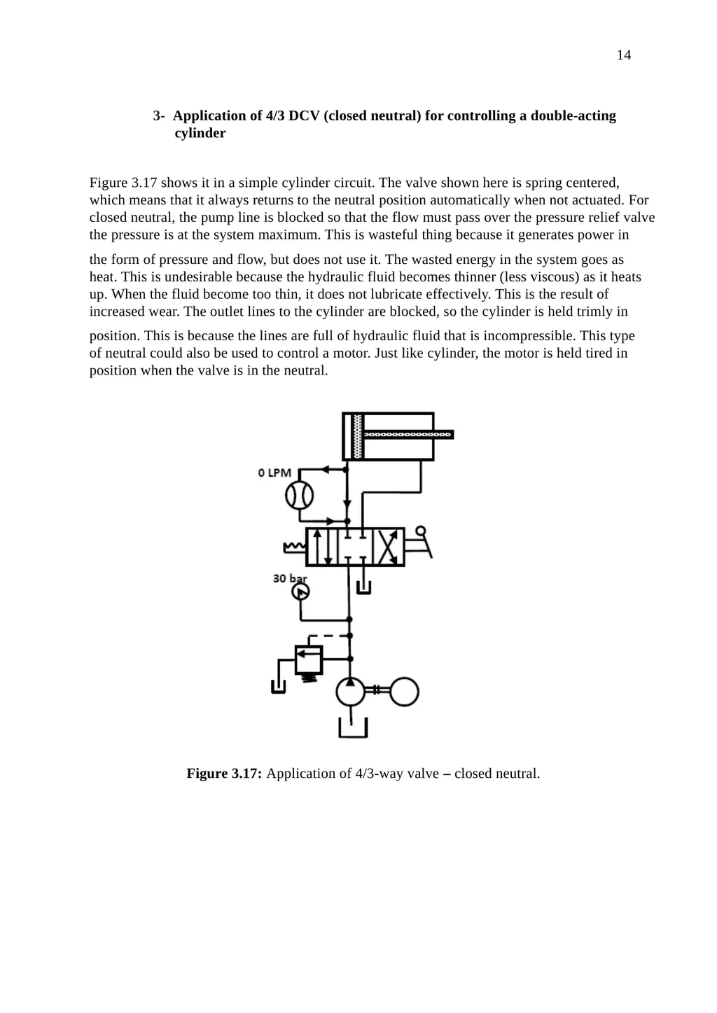
cylinder Figure 3.17 shows it in a simple cylinder circuit. The valve shown here is spring centered,
which means that it always returns to the neutral position automatically when not actuated. For
closed neutral, the pump line is blocked so that the flow must pass over the pressure relief valve
the pressure is at the system maximum. This is wasteful thing because it generates power in the form of pressure and flow, but does not use it. The wasted energy in the system goes as
heat. This is undesirable because the hydraulic fluid becomes thinner (less viscous) as it heats
up. When the fluid become too thin, it does not lubricate effectively. This is the result of
increased wear. The outlet lines to the cylinder are blocked, so the cylinder is held trimly in position. This is because the lines are full of hydraulic fluid that is incompressible. This type
of neutral could also be used to control a motor. Just like cylinder, the motor is held tired in
position when the valve is in the neutral. Figure 3.17: Application of 4/3-way valve – closed neutral.<br>
cylinder Figure 3.17 shows it in a simple cylinder circuit. The valve shown here is spring centered,
which means that it always returns to the neutral position automatically when not actuated. For
closed neutral, the pump line is blocked so that the flow must pass over the pressure relief valve
the pressure is at the system maximum. This is wasteful thing because it generates power in the form of pressure and flow, but does not use it. The wasted energy in the system goes as
heat. This is undesirable because the hydraulic fluid becomes thinner (less viscous) as it heats
up. When the fluid become too thin, it does not lubricate effectively. This is the result of
increased wear. The outlet lines to the cylinder are blocked, so the cylinder is held trimly in position. This is because the lines are full of hydraulic fluid that is incompressible. This type
of neutral could also be used to control a motor. Just like cylinder, the motor is held tired in
position when the valve is in the neutral. Figure 3.17: Application of 4/3-way valve – closed neutral.<br>
15
15 4- Application of 4/3 DCV (tandem neutral) for controlling a double-acting
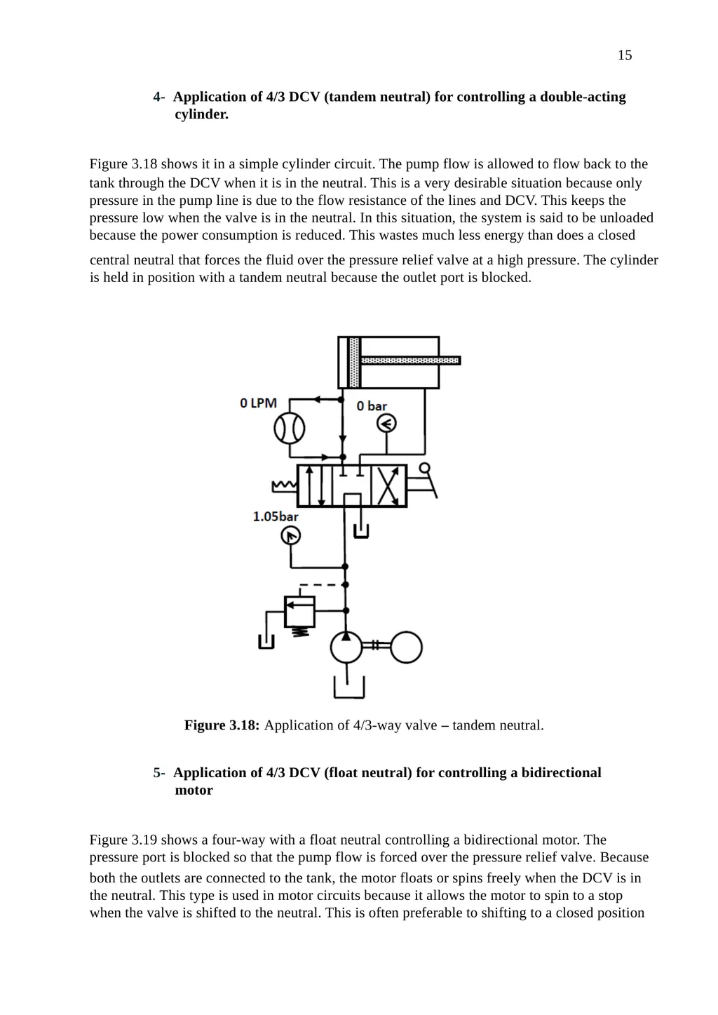
cylinder. Figure 3.18 shows it in a simple cylinder circuit. The pump flow is allowed to flow back to the tank through the DCV when it is in the neutral. This is a very desirable situation because only
pressure in the pump line is due to the flow resistance of the lines and DCV. This keeps the
pressure low when the valve is in the neutral. In this situation, the system is said to be unloaded
because the power consumption is reduced. This wastes much less energy than does a closed central neutral that forces the fluid over the pressure relief valve at a high pressure. The cylinder
is held in position with a tandem neutral because the outlet port is blocked. Figure 3.18: Application of 4/3-way valve – tandem neutral. 5- Application of 4/3 DCV (float neutral) for controlling a bidirectional
motor Figure 3.19 shows a four-way with a float neutral controlling a bidirectional motor. The
pressure port is blocked so that the pump flow is forced over the pressure relief valve. Because both the outlets are connected to the tank, the motor floats or spins freely when the DCV is in
the neutral. This type is used in motor circuits because it allows the motor to spin to a stop
when the valve is shifted to the neutral. This is often preferable to shifting to a closed position<br>
cylinder. Figure 3.18 shows it in a simple cylinder circuit. The pump flow is allowed to flow back to the tank through the DCV when it is in the neutral. This is a very desirable situation because only
pressure in the pump line is due to the flow resistance of the lines and DCV. This keeps the
pressure low when the valve is in the neutral. In this situation, the system is said to be unloaded
because the power consumption is reduced. This wastes much less energy than does a closed central neutral that forces the fluid over the pressure relief valve at a high pressure. The cylinder
is held in position with a tandem neutral because the outlet port is blocked. Figure 3.18: Application of 4/3-way valve – tandem neutral. 5- Application of 4/3 DCV (float neutral) for controlling a bidirectional
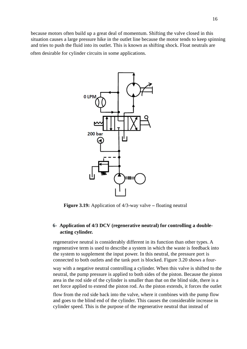
motor Figure 3.19 shows a four-way with a float neutral controlling a bidirectional motor. The
pressure port is blocked so that the pump flow is forced over the pressure relief valve. Because both the outlets are connected to the tank, the motor floats or spins freely when the DCV is in
the neutral. This type is used in motor circuits because it allows the motor to spin to a stop
when the valve is shifted to the neutral. This is often preferable to shifting to a closed position<br>
16
16 because motors often build up a great deal of momentum. Shifting the valve closed in this
situation causes a large pressure hike in the outlet line because the motor tends to keep spinning
and tries to push the fluid into its outlet. This is known as shifting shock. Float neutrals are often desirable for cylinder circuits in some applications. Figure 3.19: Application of 4/3-way valve – floating neutral 6- Application of 4/3 DCV (regenerative neutral) for controlling a double- acting cylinder. regenerative neutral is considerably different in its function than other types. A
regenerative term is used to describe a system in which the waste is feedback into
the system to supplement the input power. In this neutral, the pressure port is
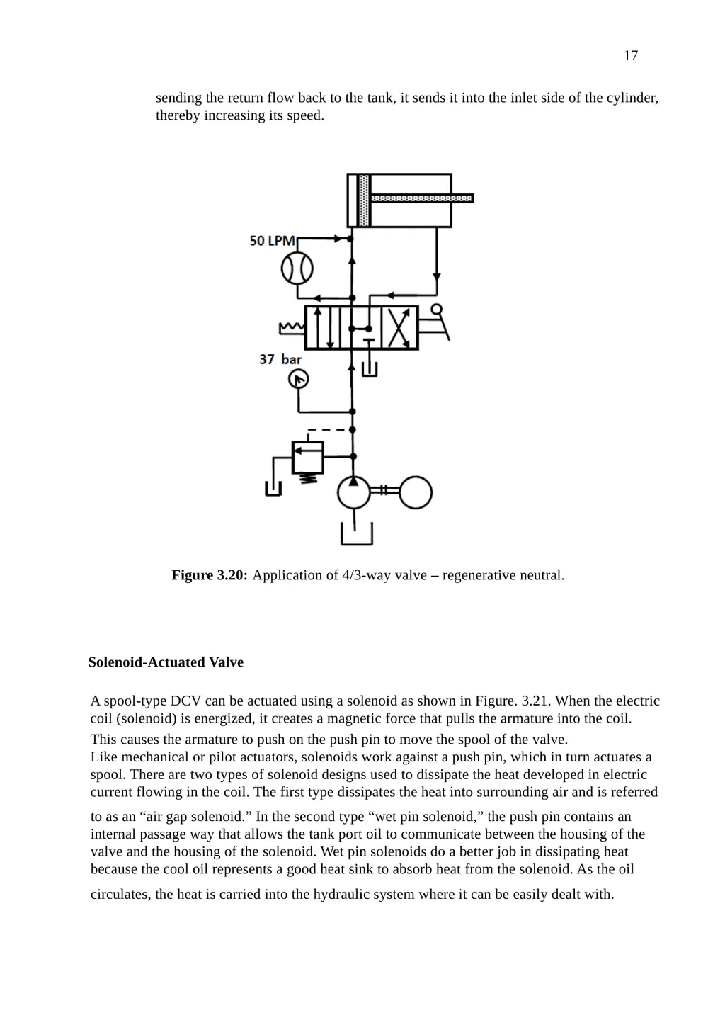
connected to both outlets and the tank port is blocked. Figure 3.20 shows a four- way with a negative neutral controlling a cylinder. When this valve is shifted to the
neutral, the pump pressure is applied to both sides of the piston. Because the piston
area in the rod side of the cylinder is smaller than that on the blind side, there is a
net force applied to extend the piston rod. As the piston extends, it forces the outlet flow from the rod side back into the valve, where it combines with the pump flow
and goes to the blind end of the cylinder. This causes the considerable increase in
cylinder speed. This is the purpose of the regenerative neutral that instead of<br>
situation causes a large pressure hike in the outlet line because the motor tends to keep spinning
and tries to push the fluid into its outlet. This is known as shifting shock. Float neutrals are often desirable for cylinder circuits in some applications. Figure 3.19: Application of 4/3-way valve – floating neutral 6- Application of 4/3 DCV (regenerative neutral) for controlling a double- acting cylinder. regenerative neutral is considerably different in its function than other types. A
regenerative term is used to describe a system in which the waste is feedback into
the system to supplement the input power. In this neutral, the pressure port is
connected to both outlets and the tank port is blocked. Figure 3.20 shows a four- way with a negative neutral controlling a cylinder. When this valve is shifted to the
neutral, the pump pressure is applied to both sides of the piston. Because the piston
area in the rod side of the cylinder is smaller than that on the blind side, there is a
net force applied to extend the piston rod. As the piston extends, it forces the outlet flow from the rod side back into the valve, where it combines with the pump flow
and goes to the blind end of the cylinder. This causes the considerable increase in
cylinder speed. This is the purpose of the regenerative neutral that instead of<br>
17
17 sending the return flow back to the tank, it sends it into the inlet side of the cylinder,
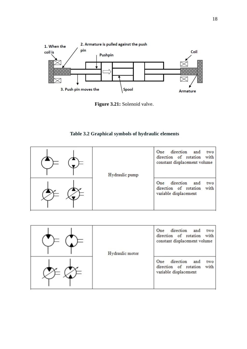
thereby increasing its speed. Figure 3.20: Application of 4/3-way valve – regenerative neutral. Solenoid-Actuated Valve A spool-type DCV can be actuated using a solenoid as shown in Figure. 3.21. When the electric
coil (solenoid) is energized, it creates a magnetic force that pulls the armature into the coil. This causes the armature to push on the push pin to move the spool of the valve.
Like mechanical or pilot actuators, solenoids work against a push pin, which in turn actuates a
spool. There are two types of solenoid designs used to dissipate the heat developed in electric
current flowing in the coil. The first type dissipates the heat into surrounding air and is referred to as an “air gap solenoid.” In the second type “wet pin solenoid,” the push pin contains an
internal passage way that allows the tank port oil to communicate between the housing of the
valve and the housing of the solenoid. Wet pin solenoids do a better job in dissipating heat
because the cool oil represents a good heat sink to absorb heat from the solenoid. As the oil circulates, the heat is carried into the hydraulic system where it can be easily dealt with.<br>
thereby increasing its speed. Figure 3.20: Application of 4/3-way valve – regenerative neutral. Solenoid-Actuated Valve A spool-type DCV can be actuated using a solenoid as shown in Figure. 3.21. When the electric
coil (solenoid) is energized, it creates a magnetic force that pulls the armature into the coil. This causes the armature to push on the push pin to move the spool of the valve.
Like mechanical or pilot actuators, solenoids work against a push pin, which in turn actuates a
spool. There are two types of solenoid designs used to dissipate the heat developed in electric
current flowing in the coil. The first type dissipates the heat into surrounding air and is referred to as an “air gap solenoid.” In the second type “wet pin solenoid,” the push pin contains an
internal passage way that allows the tank port oil to communicate between the housing of the
valve and the housing of the solenoid. Wet pin solenoids do a better job in dissipating heat
because the cool oil represents a good heat sink to absorb heat from the solenoid. As the oil circulates, the heat is carried into the hydraulic system where it can be easily dealt with.<br>
18
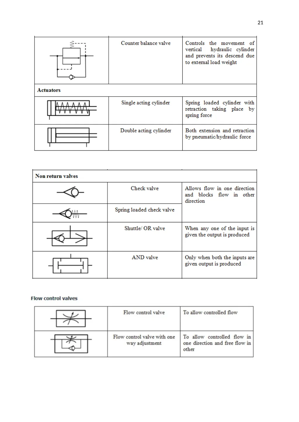
18 Figure 3.21: Solenoid valve. Table 3.2 Graphical symbols of hydraulic elements<br>
19
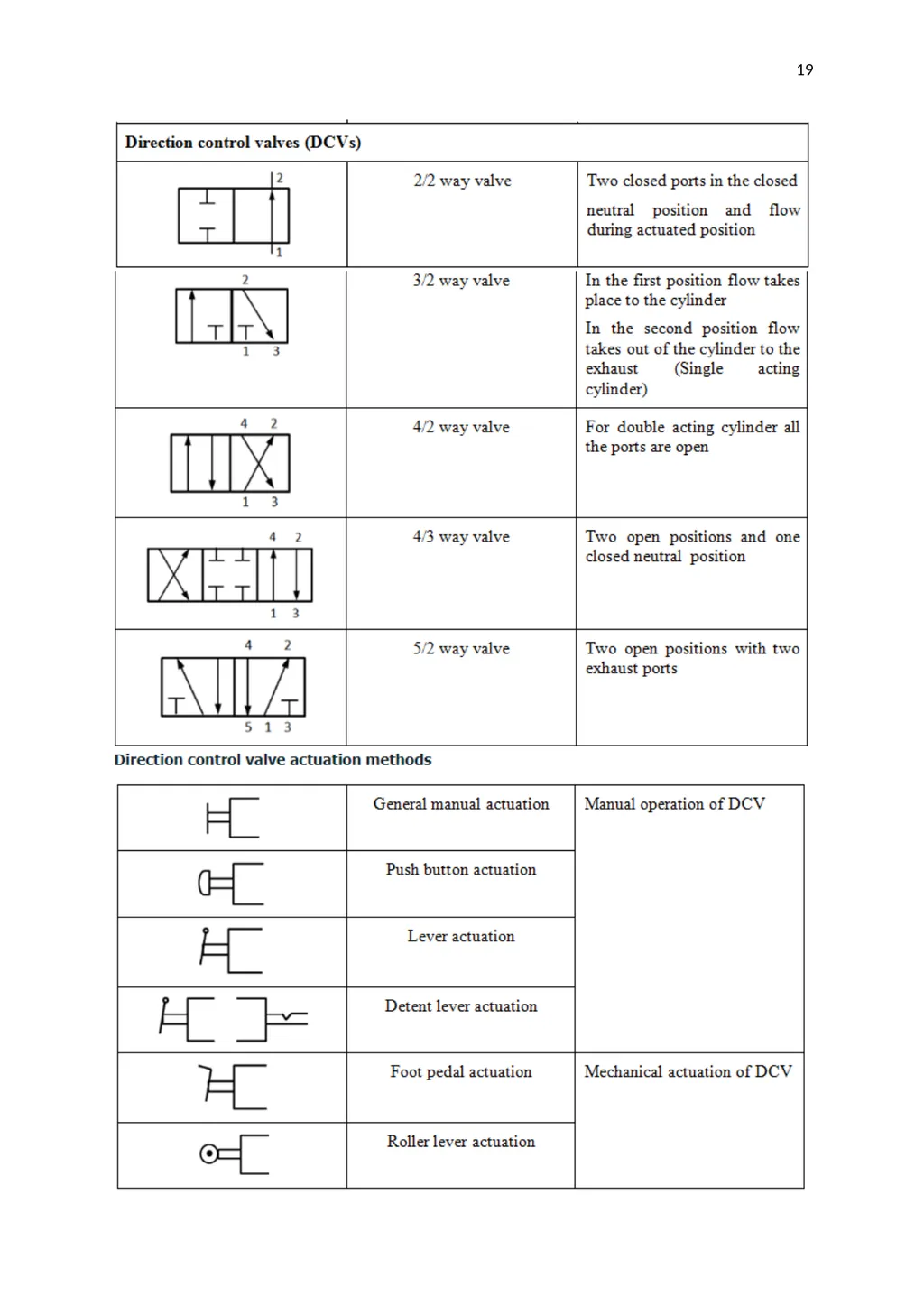
19<br>
20
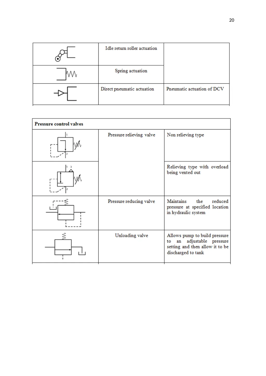
20<br>
21
21<br>