
100% Clean, Renewable Energy and Storage for


Description: 100 Clean, Renewable Energy and Storage for Everything Mark Z. Jacobson Stanford University Chapter 4: Electricity Basics Definitions Electricity Free flowing movement of charged particles, either Negatively-charged electrons
Related Topics
Download Presentation
"100% Clean, Renewable Energy and Storage for" is the property of its rightful owner. Permission is granted to download and print the materials on this website for personal, non-commercial use only, and to display it on your personal computer provided you do not modify the materials and that you retain all copyright notices contained in the materials. By downloading content from our website, you accept the terms of this agreement.
Presentation Transcript
slide1. 100% Clean, Renewable Energy and Storage for Everything Mark Z. Jacobson
Stanford University<br>
slide2. Chapter 4: Electricity Basics<br>
slide3. Definitions<br>
slide4. Electricity Free flowing movement of charged particles, either
Negatively-charged electrons
Negatively-charged ions
Positively-charged ions
Electric current
Flow of electric charge through either air or wire
Types of electricity
Static electricity
Lightning
Wired electricity<br>
slide5. Wired Electricity In a wire, atomic nuclei stay in a fixed position and electrons far from their nucleus freely move about.
These conduction electrons wander from atom to atom and their movement constitutes an electric current.
1 C = charge of 6.242 x 10¹⁸ electrons
1 A = 1 C/s (1 C of charge passes a given spot in 1 s)
Current (A) = change in charge q (C) per unit time t
i = dq/dt<br>
slide6. Direct Current vs Alternating Current Charges can be + or -. Direction of current = direction of + flow.
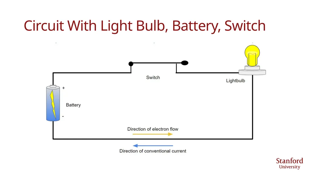
Electrons moving to right means current is flowing to left
Direct current
Charge flows at constant rate in one direction.
Alternating current
Electrons flows to right then left then right sinusoidally over time
U.S.: AC current 60 Hz = 60 cycles per second
Europe: AC current 50 Hz<br>
slide7. Circuit With Light Bulb, Battery, Switch<br>
slide8. Drift Velocity Average speed of the net flow of electrons
As electrons collide with each other, they transfer energy to each other causing a wave of electricity to travel down a wire at nearly the speed of light, but electrons themselves move slowly
With AC electricity, electrons reverse direction 60 times per second (in U.S.), so they barely move at all.<br>
slide9. Drift Velocity vd = current / (electrons per unit volume of wire x Coulombs per electron x area of wire)
Find drift velocity in copper wire of area 3.31x10⁻⁶ m2 if current = 20 A
Cu molecular weight 63.55 g/mol; density 8,960 kg/m3; and 1 electron per atom
e-/m3 = 1 e-/atom x 6.023x10²³atoms/mol x 1 mol/63.55 g x 8.96x106 g/m3
= 8.49x1028 electrons per m3
vd = 20 C/s / (8.49x1028 e-/m3 x 1.602x10-19 C/e- x 3.31x10⁻⁶ m2)
= 0.00044 m/s = 1.6 m/hr
Thus, the bulk movement of electrons is slow, but they don’t need to move fast to carry a large amount of current.<br>
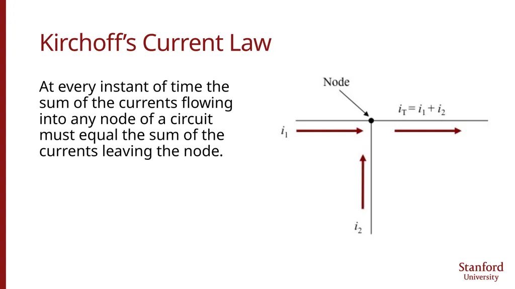
slide10. Kirchoff’s Current Law At every instant of time the sum of the currents flowing into any node of a circuit must equal the sum of the currents leaving the node.<br>
slide11. Voltage = Energy (dw, J) carried by a single charge (dq, C)
v = dw/dq
Just as a lifted mass gains potential energy; a charge with its voltage raised gains electrical energy
A 12-V battery provides 12 J of energy for every 1 C of charge it stores
Voltage is measured across components. Voltage across battery is 12 V
Voltage rises across a battery 12 V and drops across a lightbulb
Current is measured through components. Current through battery =10 A<br>
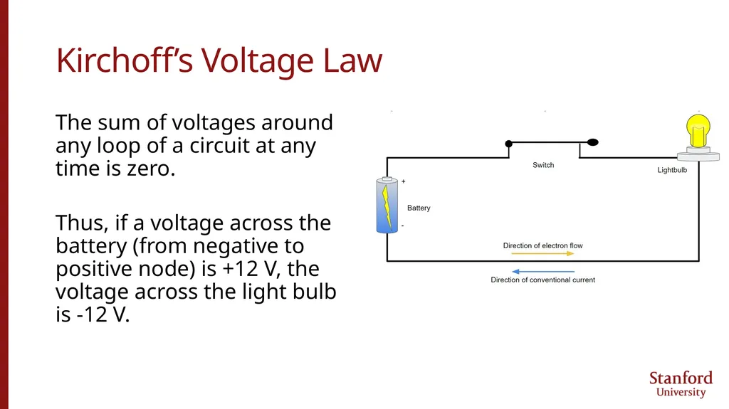
slide12. Kirchoff’s Voltage Law The sum of voltages around any loop of a circuit at any time is zero.
Thus, if a voltage across the battery (from negative to positive node) is +12 V, the voltage across the light bulb is -12 V.<br>
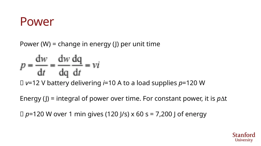
slide13. Power Power (W) = change in energy (J) per unit time
v=12 V battery delivering i=10 A to a load supplies p=120 W
Energy (J) = integral of power over time. For constant power, it is pDt
p=120 W over 1 min gives (120 J/s) x 60 s = 7,200 J of energy<br>
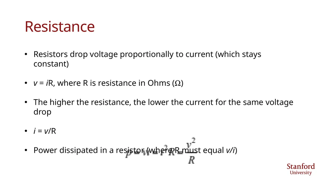
slide14. Resistance Resistors drop voltage proportionally to current (which stays constant)
v = iR, where R is resistance in Ohms (W)
The higher the resistance, the lower the current for the same voltage drop
i = v/R
Power dissipated in a resistor (where R must equal v/i)<br>
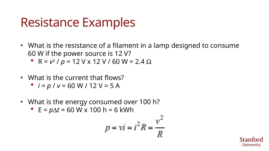
slide15. Resistance Examples What is the resistance of a filament in a lamp designed to consume 60 W if the power source is 12 V?
R = v2 / p = 12 V x 12 V / 60 W = 2.4 W
What is the current that flows?
i = p / v = 60 W / 12 V = 5 A
What is the energy consumed over 100 h?
E = pDt = 60 W x 100 h = 6 kWh<br>
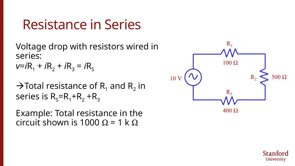
slide16. Resistance in Series Voltage drop with resistors wired in series:
v=iR1 + iR2 + iR3 = iRS
Total resistance of R1 and R2 in series is RS=R1+R2 +R3
Example: Total resistance in the circuit shown is 1000 W = 1 k W<br>
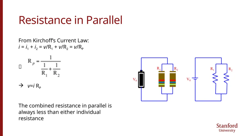
slide17. Resistance in Parallel From Kirchoff‘s Current Law:
i = i1 + i2 = v/R1 + v/R2 = v/RP
v=i RP
The combined resistance in parallel is always less than either individual resistance<br>
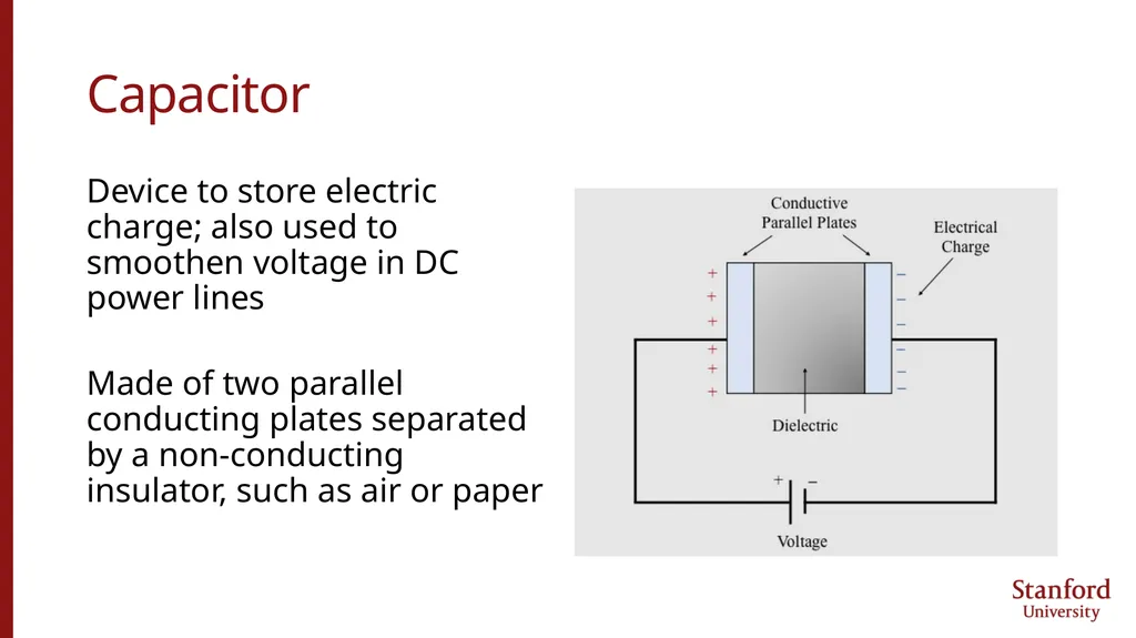
slide18. Capacitor Device to store electric charge; also used to smoothen voltage in DC power lines
Made of two parallel conducting plates separated by a non-conducting insulator, such as air or paper<br>
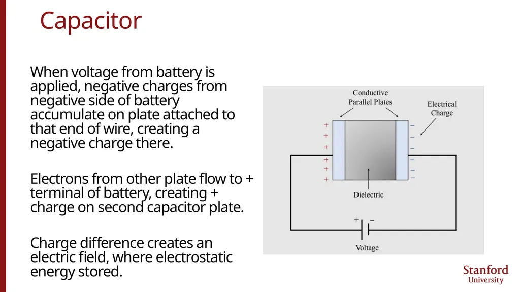
slide19. Capacitor When voltage from battery is applied, negative charges from negative side of battery accumulate on plate attached to that end of wire, creating a negative charge there.
Electrons from other plate flow to + terminal of battery, creating + charge on second capacitor plate.
Charge difference creates an electric field, where electrostatic energy stored.<br>
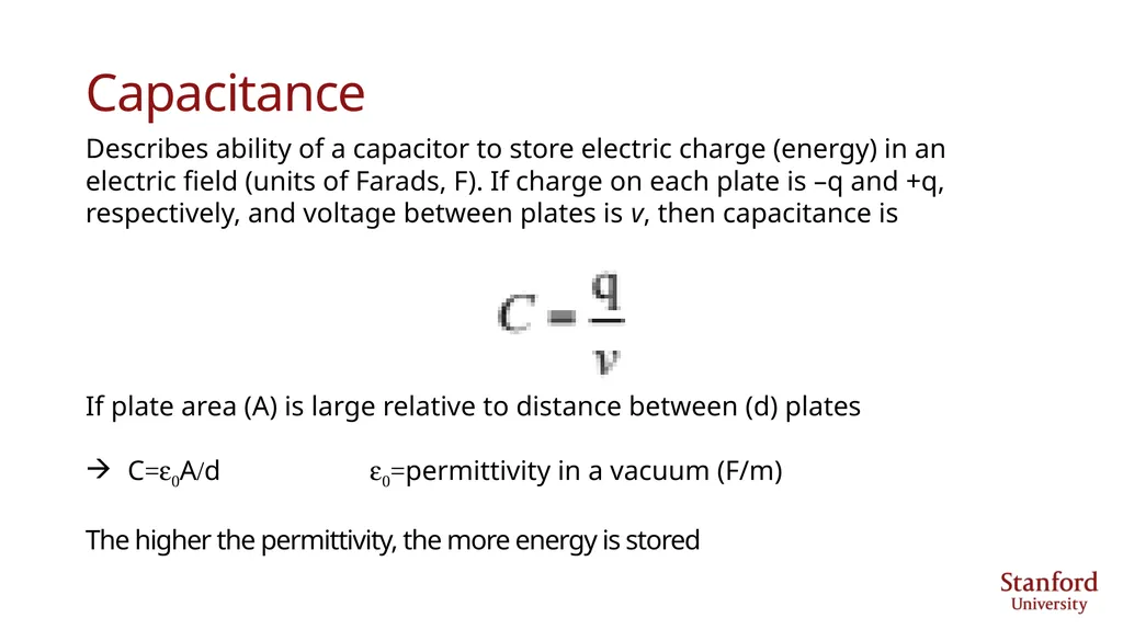
slide20. Capacitance Describes ability of a capacitor to store electric charge (energy) in an electric field (units of Farads, F). If charge on each plate is –q and +q, respectively, and voltage between plates is v, then capacitance is
If plate area (A) is large relative to distance between (d) plates
C=e0A/d e0=permittivity in a vacuum (F/m)
The higher the permittivity, the more energy is stored<br>
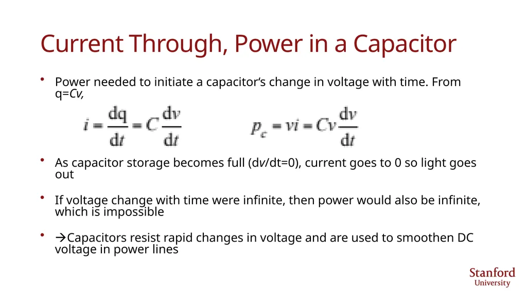
slide21. Current Through, Power in a Capacitor Power needed to initiate a capacitor‘s change in voltage with time. From q=Cv,
As capacitor storage becomes full (dv/dt=0), current goes to 0 so light goes out
If voltage change with time were infinite, then power would also be infinite, which is impossible
Capacitors resist rapid changes in voltage and are used to smoothen DC voltage in power lines<br>
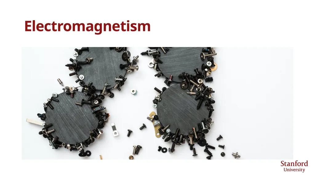
slide22. Electromagnetism<br>
slide23. Electromagnetism An electrical current flowing through a wire creates a circular magnetic field around the wire. (Orsted, 1820)
A magnet moving toward or away from a coiled wire along a circuit creates a fluctuating electric current in the wire. (Faraday)
A fluctuating current in one wire creates a fluctuating magnetic field that induces a fluctuating current in a second wire (Faraday, 1831).<br>
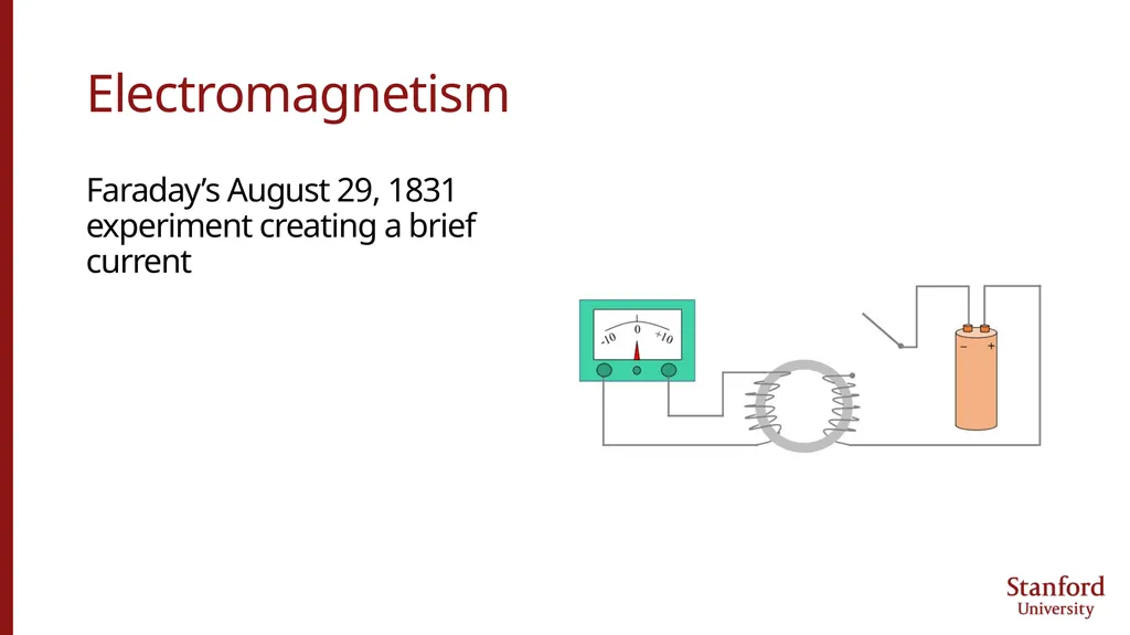
slide24. Electromagnetism Faraday’s August 29, 1831 experiment creating a brief current<br>
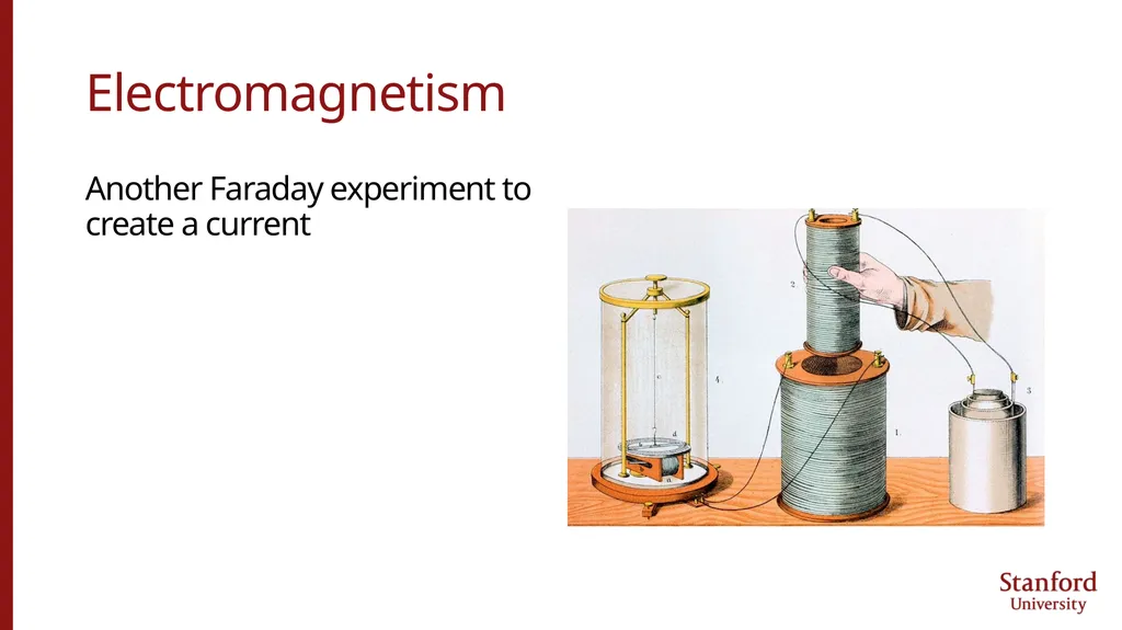
slide25. Electromagnetism Another Faraday experiment to create a current<br>
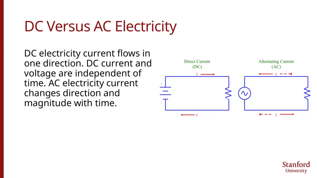
slide26. DC Versus AC Electricity DC electricity current flows in one direction. DC current and voltage are independent of time. AC electricity current changes direction and magnitude with time.<br>
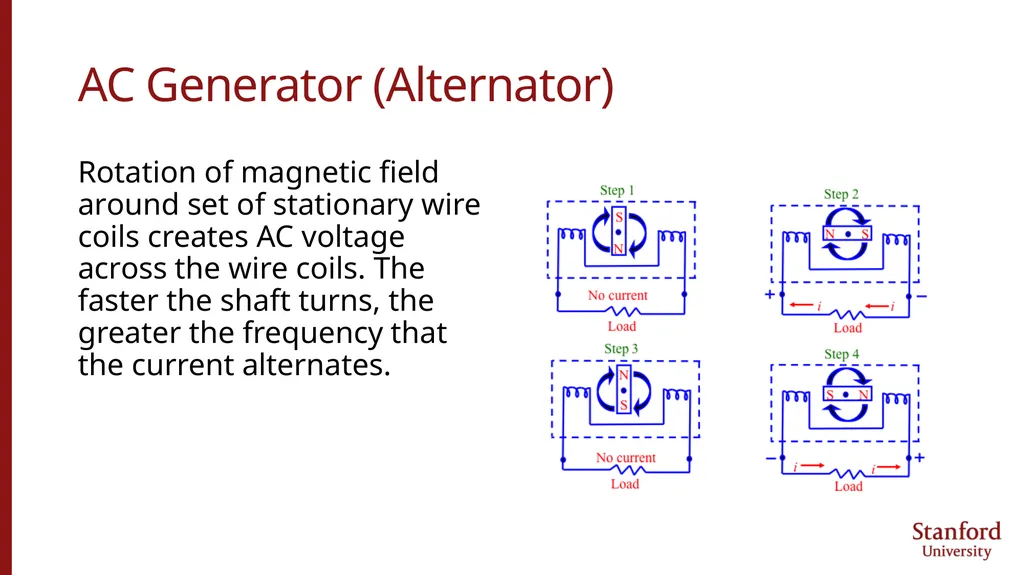
slide27. AC Generator (Alternator) Rotation of magnetic field around set of stationary wire coils creates AC voltage across the wire coils. The faster the shaft turns, the greater the frequency that the current alternates.<br>
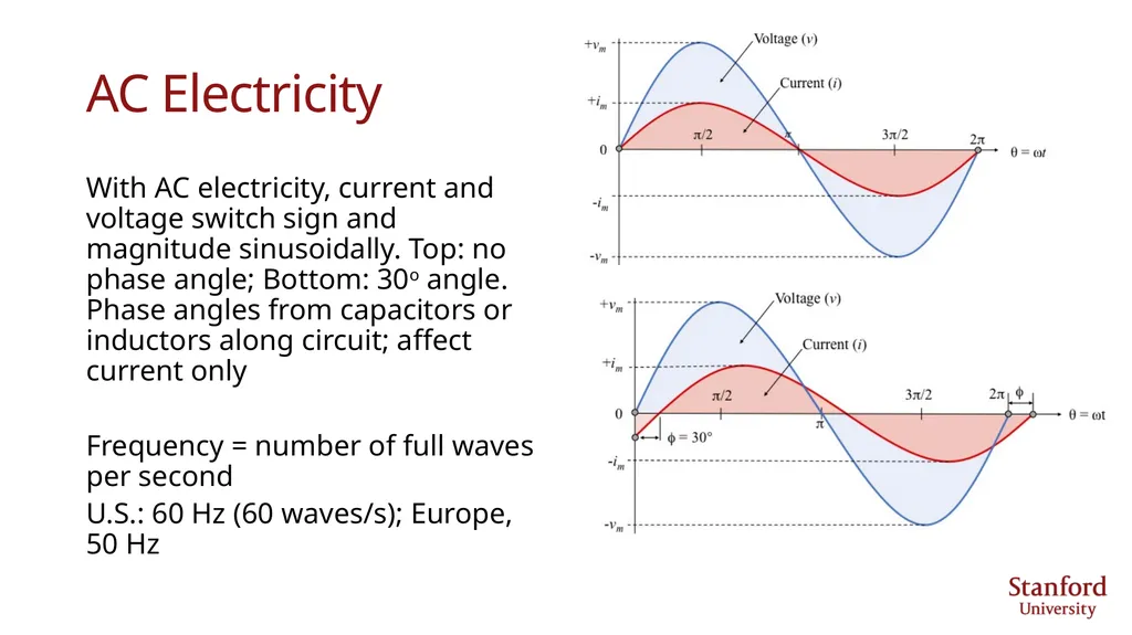
slide28. AC Electricity With AC electricity, current and voltage switch sign and magnitude sinusoidally. Top: no phase angle; Bottom: 30o angle. Phase angles from capacitors or inductors along circuit; affect current only
Frequency = number of full waves per second
U.S.: 60 Hz (60 waves/s); Europe, 50 Hz<br>
slide29. AC Electricity Voltage & current vary sinusoidally
v(t) = Vmcoswt
i(t) = Imcos(wt+f)
w=angular freq (rad/s)=2pf
f=frequency (1/s)
Period T=1/f
f=phase angle (rad)=fractional period difference between i(t), v(t) peaks<br>
slide30. AC Electricity With AC electricity, v, i are root-mean-square (rms) values and p is an average value. Thus, 120 V AC is Vrms
v=Vrms=√[(Vm2cos2wt)avg]=Vm/√2
i=Irms=√[(I2mcos2 (wt+f))avg]=Im/√2
p=vi=VrmsIrms=Pavg
Find resistance and current for 60 W bulb powered by 120 V AC:
R=v2/p=1202/60=240 W
i=p/v=60/120=0.5 A<br>
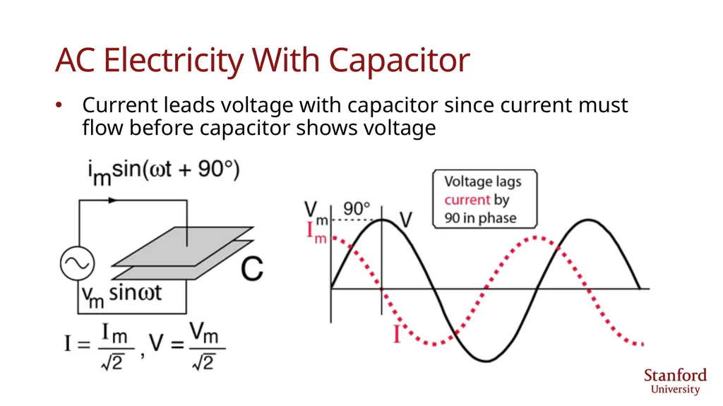
slide31. AC Electricity With Capacitor Current leads voltage with capacitor since current must flow before capacitor shows voltage<br>
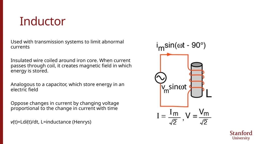
slide32. Inductor Used with transmission systems to limit abnormal currents
Insulated wire coiled around iron core. When current passes through coil, it creates magnetic field in which energy is stored.
Analogous to a capacitor, which store energy in an electric field
Oppose changes in current by changing voltage proportional to the change in current with time
v(t)=Ldi(t)/dt, L=inductance (Henrys)<br>
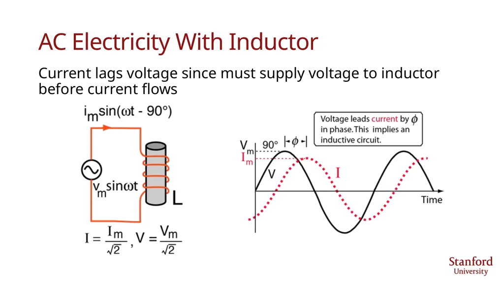
slide33. AC Electricity With Inductor Current lags voltage since must supply voltage to inductor before current flows<br>
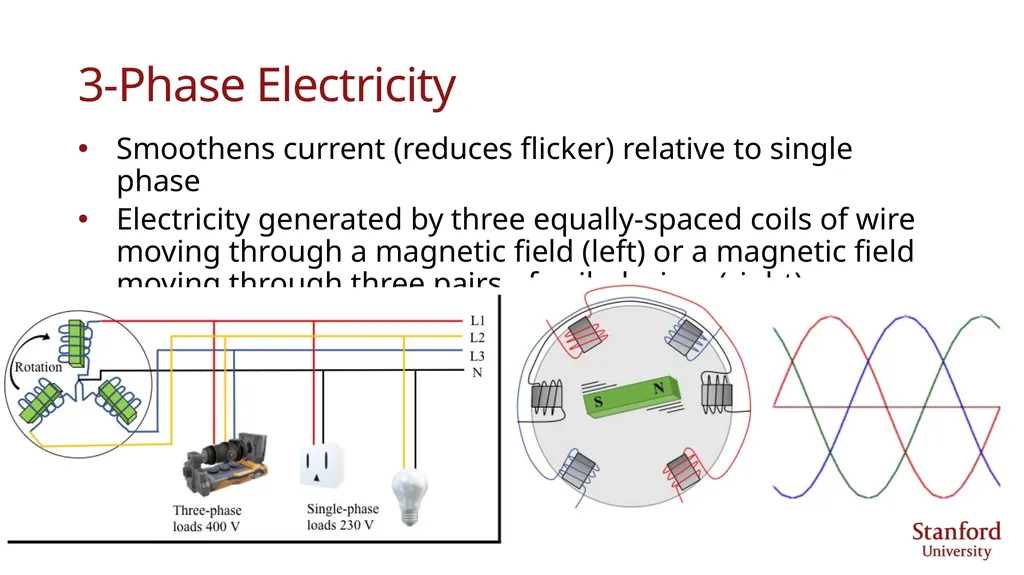
slide34. 3-Phase Electricity Smoothens current (reduces flicker) relative to single phase
Electricity generated by three equally-spaced coils of wire moving through a magnetic field (left) or a magnetic field moving through three pairs of coiled wires (right)<br>
slide35. Reactive Power Real power
Energy/time used to run a motor or heat a home. It is the result of a circuit with resistive components only (no capacitors or inductors).
Reactive power
“Imaginary” power that does not do useful work but moves back and forth within power lines. Byproduct of an AC system that has inductors or capacitors and arises due to a phase difference (f) between voltage and current. It represents the product of Volts x Amperes that are out of phase with each other<br>
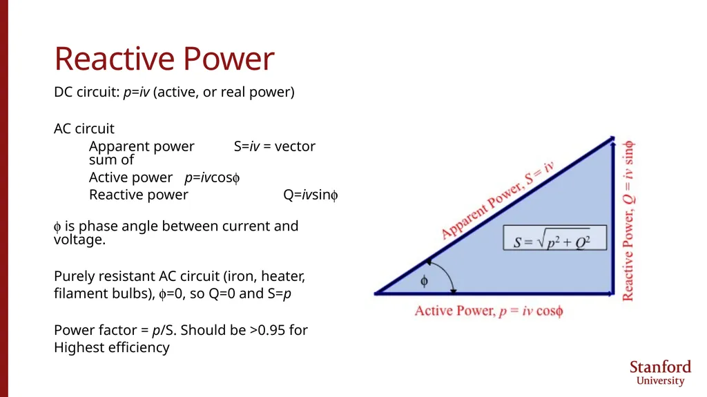
slide36. Reactive Power DC circuit: p=iv (active, or real power)
AC circuit
Apparent power S=iv = vector sum of
Active power p=ivcosf
Reactive power Q=ivsinf
f is phase angle between current and voltage.
Purely resistant AC circuit (iron, heater,
filament bulbs), f=0, so Q=0 and S=p
Power factor = p/S. Should be >0.95 for
Highest efficiency<br>
slide37. Reactive Power Reactive power important for 3 reasons:
Smoothens voltage on transmission grid by supplying or absorbing it
A sufficient amount of reactive power is needed to avoid blackouts
Transformers, motors, and generators require reactive power to produce magnetic flux<br>
slide38. Producing Reactive Power When capacitors and inductors are not sufficient, generators are used to supply or absorb reactive power to maintain a constant voltage (“voltage support”) when voltage is too low or high on the grid.
Such generators produce reactive power by raising their terminal voltage. This is accomplished by increasing the magnetic field in the generator. Such generators have high heat losses so don’t produce much real power. They are paid for reactive power.<br>
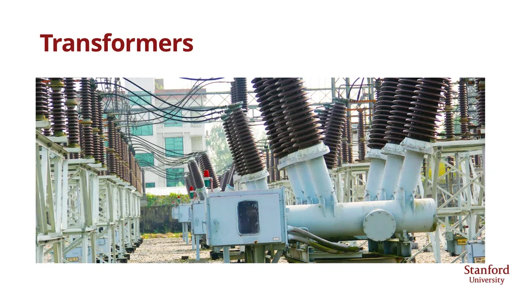
slide39. Transformers<br>
slide40. Transformers In 1882, Edison’s first electric utility (Pearl Street, NYC) used DC power
DC voltages were low (110 V), currents were high, and power losses (pw =i2Rw) were high, so voltages dropped significantly along the thick copper wires
In 1886, Westinghouse introduced the first AC grid (Great Barrington, Massachusetts) using a single-phase AC generator. He had purchased the rights to use Lucien Gaulard’s transformer and hired William Stanley to improve it.
Transformers were used to boost voltage entering transmission lines in order to reduce current, thus line losses. Voltage was reduced back down to safe levels at customer locations.<br>
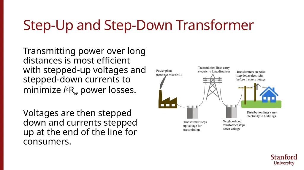
slide41. Step-Up and Step-Down Transformer Transmitting power over long distances is most efficient with stepped-up voltages and stepped-down currents to minimize i2Rw power losses.
Voltages are then stepped down and currents stepped up at the end of the line for consumers.<br>
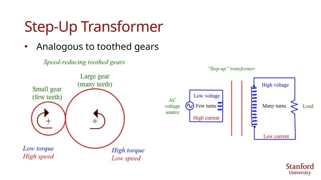
slide42. Step-Up Transformer Analogous to toothed gears<br>
slide43. Transformers A transformer steps voltage up or down from a powered coil to an unpowered coil.
The AC voltage induced in the unpowered coil equals that in the powered coil multiplied by the ratio of secondary coil turns to primary coil turns.
Transformers don’t work with DC<br>
slide44. Decreasing Current Reduces Line Losses Doubling v along a transmission line reduces i by a factor of 2 at same power since p=vi.
Power loss along a wire,
pw=vwi=i2Rw= (p/v)2Rw
where vw=iRw is the voltage loss across the wire.
Cutting i in half decreases power loss by a factor of 4.
Raising end voltage (v) by a factor of 10 decreases line loss by a factor of 100.
Modern systems generate 12-25 kV. Transformers boost that to 100-1000 kV and down again to 4-35 kV<br>
slide45. AC Versus DC In 1887, C.S. Bradley invented 3-phase AC generator.
By 1887, Westinghouse had half the number of AC generating stations as Edison had DC stations
In 1888, Tesla invented 3-phase AC induction motor, which was critical for powering equipment on an AC grid.
Westinghouse then hired Tesla to improve AC grid, AC generators, and AC motors.
In 1891, Westinghouse built first power plant (hydro) to supply AC electricity over long distance (5.6 km) for a gold mine in Ophir, CO<br>
slide46. AC Versus DC Edison declined to invest in AC.
In Nov. 1887, dentist Alfred Southwick asked Edison to support the use of electricity to execute criminals.
Edison didn’t believe in capital punishment but believed Westinghouse should be punished: “The most effective of these are known as alternating machines manufactured principally in this country by Mr. Geo. Westinghouse, Pittsburgh.” Edison lobbied and succeeded in having first electric chair use AC (1890)
Edison hired Harold Brown to stoke fears about AC electricity. Demonstrated electrocution of dogs, horses, calves to audiences.<br>
slide47. AC Versus DC By 1891, AC had all but taken over.
DC could operate only a few appliances; AC, many.
AC less expensive and could run on larger, more distant power supplies.
With adoption of AC at the Chicago World’s Fair in 1893 and at the New York Niagara Falls power station in 1895, AC completed its takeover.<br>
slide48. HVDC Transmission High-voltage direct current (HVDC) uses DC for most of the transmission distance. Obtained by converting HVAC to HVDC then back to HVAC with thyristor or transistor.
For long distance (> 600 km), HVDC has lower line losses than HVAC and costs less.
For short distance (< 600 km), HVAC costs less because of greater conversion equipment for HVDC.
HVDC uses voltages 100 kV to 1,500 kV.<br>
slide49. 120 V – 240 V Outlets Home wall receptor receives 60 Hz AC power at 120 V (110-125 V). Some appliances (e.g., dryer) require 240 V.
Transformer on power pole steps down voltage from utility distribution from 4.16-34.5 kV to 120 V or 240 V.<br>
Stanford University<br>
slide2. Chapter 4: Electricity Basics<br>
slide3. Definitions<br>
slide4. Electricity Free flowing movement of charged particles, either
Negatively-charged electrons
Negatively-charged ions
Positively-charged ions
Electric current
Flow of electric charge through either air or wire
Types of electricity
Static electricity
Lightning
Wired electricity<br>
slide5. Wired Electricity In a wire, atomic nuclei stay in a fixed position and electrons far from their nucleus freely move about.
These conduction electrons wander from atom to atom and their movement constitutes an electric current.
1 C = charge of 6.242 x 10¹⁸ electrons
1 A = 1 C/s (1 C of charge passes a given spot in 1 s)
Current (A) = change in charge q (C) per unit time t
i = dq/dt<br>
slide6. Direct Current vs Alternating Current Charges can be + or -. Direction of current = direction of + flow.
Electrons moving to right means current is flowing to left
Direct current
Charge flows at constant rate in one direction.
Alternating current
Electrons flows to right then left then right sinusoidally over time
U.S.: AC current 60 Hz = 60 cycles per second
Europe: AC current 50 Hz<br>
slide7. Circuit With Light Bulb, Battery, Switch<br>
slide8. Drift Velocity Average speed of the net flow of electrons
As electrons collide with each other, they transfer energy to each other causing a wave of electricity to travel down a wire at nearly the speed of light, but electrons themselves move slowly
With AC electricity, electrons reverse direction 60 times per second (in U.S.), so they barely move at all.<br>
slide9. Drift Velocity vd = current / (electrons per unit volume of wire x Coulombs per electron x area of wire)
Find drift velocity in copper wire of area 3.31x10⁻⁶ m2 if current = 20 A
Cu molecular weight 63.55 g/mol; density 8,960 kg/m3; and 1 electron per atom
e-/m3 = 1 e-/atom x 6.023x10²³atoms/mol x 1 mol/63.55 g x 8.96x106 g/m3
= 8.49x1028 electrons per m3
vd = 20 C/s / (8.49x1028 e-/m3 x 1.602x10-19 C/e- x 3.31x10⁻⁶ m2)
= 0.00044 m/s = 1.6 m/hr
Thus, the bulk movement of electrons is slow, but they don’t need to move fast to carry a large amount of current.<br>
slide10. Kirchoff’s Current Law At every instant of time the sum of the currents flowing into any node of a circuit must equal the sum of the currents leaving the node.<br>
slide11. Voltage = Energy (dw, J) carried by a single charge (dq, C)
v = dw/dq
Just as a lifted mass gains potential energy; a charge with its voltage raised gains electrical energy
A 12-V battery provides 12 J of energy for every 1 C of charge it stores
Voltage is measured across components. Voltage across battery is 12 V
Voltage rises across a battery 12 V and drops across a lightbulb
Current is measured through components. Current through battery =10 A<br>
slide12. Kirchoff’s Voltage Law The sum of voltages around any loop of a circuit at any time is zero.
Thus, if a voltage across the battery (from negative to positive node) is +12 V, the voltage across the light bulb is -12 V.<br>
slide13. Power Power (W) = change in energy (J) per unit time
v=12 V battery delivering i=10 A to a load supplies p=120 W
Energy (J) = integral of power over time. For constant power, it is pDt
p=120 W over 1 min gives (120 J/s) x 60 s = 7,200 J of energy<br>
slide14. Resistance Resistors drop voltage proportionally to current (which stays constant)
v = iR, where R is resistance in Ohms (W)
The higher the resistance, the lower the current for the same voltage drop
i = v/R
Power dissipated in a resistor (where R must equal v/i)<br>
slide15. Resistance Examples What is the resistance of a filament in a lamp designed to consume 60 W if the power source is 12 V?
R = v2 / p = 12 V x 12 V / 60 W = 2.4 W
What is the current that flows?
i = p / v = 60 W / 12 V = 5 A
What is the energy consumed over 100 h?
E = pDt = 60 W x 100 h = 6 kWh<br>
slide16. Resistance in Series Voltage drop with resistors wired in series:
v=iR1 + iR2 + iR3 = iRS
Total resistance of R1 and R2 in series is RS=R1+R2 +R3
Example: Total resistance in the circuit shown is 1000 W = 1 k W<br>
slide17. Resistance in Parallel From Kirchoff‘s Current Law:
i = i1 + i2 = v/R1 + v/R2 = v/RP
v=i RP
The combined resistance in parallel is always less than either individual resistance<br>
slide18. Capacitor Device to store electric charge; also used to smoothen voltage in DC power lines
Made of two parallel conducting plates separated by a non-conducting insulator, such as air or paper<br>
slide19. Capacitor When voltage from battery is applied, negative charges from negative side of battery accumulate on plate attached to that end of wire, creating a negative charge there.
Electrons from other plate flow to + terminal of battery, creating + charge on second capacitor plate.
Charge difference creates an electric field, where electrostatic energy stored.<br>
slide20. Capacitance Describes ability of a capacitor to store electric charge (energy) in an electric field (units of Farads, F). If charge on each plate is –q and +q, respectively, and voltage between plates is v, then capacitance is
If plate area (A) is large relative to distance between (d) plates
C=e0A/d e0=permittivity in a vacuum (F/m)
The higher the permittivity, the more energy is stored<br>
slide21. Current Through, Power in a Capacitor Power needed to initiate a capacitor‘s change in voltage with time. From q=Cv,
As capacitor storage becomes full (dv/dt=0), current goes to 0 so light goes out
If voltage change with time were infinite, then power would also be infinite, which is impossible
Capacitors resist rapid changes in voltage and are used to smoothen DC voltage in power lines<br>
slide22. Electromagnetism<br>
slide23. Electromagnetism An electrical current flowing through a wire creates a circular magnetic field around the wire. (Orsted, 1820)
A magnet moving toward or away from a coiled wire along a circuit creates a fluctuating electric current in the wire. (Faraday)
A fluctuating current in one wire creates a fluctuating magnetic field that induces a fluctuating current in a second wire (Faraday, 1831).<br>
slide24. Electromagnetism Faraday’s August 29, 1831 experiment creating a brief current<br>
slide25. Electromagnetism Another Faraday experiment to create a current<br>
slide26. DC Versus AC Electricity DC electricity current flows in one direction. DC current and voltage are independent of time. AC electricity current changes direction and magnitude with time.<br>
slide27. AC Generator (Alternator) Rotation of magnetic field around set of stationary wire coils creates AC voltage across the wire coils. The faster the shaft turns, the greater the frequency that the current alternates.<br>
slide28. AC Electricity With AC electricity, current and voltage switch sign and magnitude sinusoidally. Top: no phase angle; Bottom: 30o angle. Phase angles from capacitors or inductors along circuit; affect current only
Frequency = number of full waves per second
U.S.: 60 Hz (60 waves/s); Europe, 50 Hz<br>
slide29. AC Electricity Voltage & current vary sinusoidally
v(t) = Vmcoswt
i(t) = Imcos(wt+f)
w=angular freq (rad/s)=2pf
f=frequency (1/s)
Period T=1/f
f=phase angle (rad)=fractional period difference between i(t), v(t) peaks<br>
slide30. AC Electricity With AC electricity, v, i are root-mean-square (rms) values and p is an average value. Thus, 120 V AC is Vrms
v=Vrms=√[(Vm2cos2wt)avg]=Vm/√2
i=Irms=√[(I2mcos2 (wt+f))avg]=Im/√2
p=vi=VrmsIrms=Pavg
Find resistance and current for 60 W bulb powered by 120 V AC:
R=v2/p=1202/60=240 W
i=p/v=60/120=0.5 A<br>
slide31. AC Electricity With Capacitor Current leads voltage with capacitor since current must flow before capacitor shows voltage<br>
slide32. Inductor Used with transmission systems to limit abnormal currents
Insulated wire coiled around iron core. When current passes through coil, it creates magnetic field in which energy is stored.
Analogous to a capacitor, which store energy in an electric field
Oppose changes in current by changing voltage proportional to the change in current with time
v(t)=Ldi(t)/dt, L=inductance (Henrys)<br>
slide33. AC Electricity With Inductor Current lags voltage since must supply voltage to inductor before current flows<br>
slide34. 3-Phase Electricity Smoothens current (reduces flicker) relative to single phase
Electricity generated by three equally-spaced coils of wire moving through a magnetic field (left) or a magnetic field moving through three pairs of coiled wires (right)<br>
slide35. Reactive Power Real power
Energy/time used to run a motor or heat a home. It is the result of a circuit with resistive components only (no capacitors or inductors).
Reactive power
“Imaginary” power that does not do useful work but moves back and forth within power lines. Byproduct of an AC system that has inductors or capacitors and arises due to a phase difference (f) between voltage and current. It represents the product of Volts x Amperes that are out of phase with each other<br>
slide36. Reactive Power DC circuit: p=iv (active, or real power)
AC circuit
Apparent power S=iv = vector sum of
Active power p=ivcosf
Reactive power Q=ivsinf
f is phase angle between current and voltage.
Purely resistant AC circuit (iron, heater,
filament bulbs), f=0, so Q=0 and S=p
Power factor = p/S. Should be >0.95 for
Highest efficiency<br>
slide37. Reactive Power Reactive power important for 3 reasons:
Smoothens voltage on transmission grid by supplying or absorbing it
A sufficient amount of reactive power is needed to avoid blackouts
Transformers, motors, and generators require reactive power to produce magnetic flux<br>
slide38. Producing Reactive Power When capacitors and inductors are not sufficient, generators are used to supply or absorb reactive power to maintain a constant voltage (“voltage support”) when voltage is too low or high on the grid.
Such generators produce reactive power by raising their terminal voltage. This is accomplished by increasing the magnetic field in the generator. Such generators have high heat losses so don’t produce much real power. They are paid for reactive power.<br>
slide39. Transformers<br>
slide40. Transformers In 1882, Edison’s first electric utility (Pearl Street, NYC) used DC power
DC voltages were low (110 V), currents were high, and power losses (pw =i2Rw) were high, so voltages dropped significantly along the thick copper wires
In 1886, Westinghouse introduced the first AC grid (Great Barrington, Massachusetts) using a single-phase AC generator. He had purchased the rights to use Lucien Gaulard’s transformer and hired William Stanley to improve it.
Transformers were used to boost voltage entering transmission lines in order to reduce current, thus line losses. Voltage was reduced back down to safe levels at customer locations.<br>
slide41. Step-Up and Step-Down Transformer Transmitting power over long distances is most efficient with stepped-up voltages and stepped-down currents to minimize i2Rw power losses.
Voltages are then stepped down and currents stepped up at the end of the line for consumers.<br>
slide42. Step-Up Transformer Analogous to toothed gears<br>
slide43. Transformers A transformer steps voltage up or down from a powered coil to an unpowered coil.
The AC voltage induced in the unpowered coil equals that in the powered coil multiplied by the ratio of secondary coil turns to primary coil turns.
Transformers don’t work with DC<br>
slide44. Decreasing Current Reduces Line Losses Doubling v along a transmission line reduces i by a factor of 2 at same power since p=vi.
Power loss along a wire,
pw=vwi=i2Rw= (p/v)2Rw
where vw=iRw is the voltage loss across the wire.
Cutting i in half decreases power loss by a factor of 4.
Raising end voltage (v) by a factor of 10 decreases line loss by a factor of 100.
Modern systems generate 12-25 kV. Transformers boost that to 100-1000 kV and down again to 4-35 kV<br>
slide45. AC Versus DC In 1887, C.S. Bradley invented 3-phase AC generator.
By 1887, Westinghouse had half the number of AC generating stations as Edison had DC stations
In 1888, Tesla invented 3-phase AC induction motor, which was critical for powering equipment on an AC grid.
Westinghouse then hired Tesla to improve AC grid, AC generators, and AC motors.
In 1891, Westinghouse built first power plant (hydro) to supply AC electricity over long distance (5.6 km) for a gold mine in Ophir, CO<br>
slide46. AC Versus DC Edison declined to invest in AC.
In Nov. 1887, dentist Alfred Southwick asked Edison to support the use of electricity to execute criminals.
Edison didn’t believe in capital punishment but believed Westinghouse should be punished: “The most effective of these are known as alternating machines manufactured principally in this country by Mr. Geo. Westinghouse, Pittsburgh.” Edison lobbied and succeeded in having first electric chair use AC (1890)
Edison hired Harold Brown to stoke fears about AC electricity. Demonstrated electrocution of dogs, horses, calves to audiences.<br>
slide47. AC Versus DC By 1891, AC had all but taken over.
DC could operate only a few appliances; AC, many.
AC less expensive and could run on larger, more distant power supplies.
With adoption of AC at the Chicago World’s Fair in 1893 and at the New York Niagara Falls power station in 1895, AC completed its takeover.<br>
slide48. HVDC Transmission High-voltage direct current (HVDC) uses DC for most of the transmission distance. Obtained by converting HVAC to HVDC then back to HVAC with thyristor or transistor.
For long distance (> 600 km), HVDC has lower line losses than HVAC and costs less.
For short distance (< 600 km), HVAC costs less because of greater conversion equipment for HVDC.
HVDC uses voltages 100 kV to 1,500 kV.<br>
slide49. 120 V – 240 V Outlets Home wall receptor receives 60 Hz AC power at 120 V (110-125 V). Some appliances (e.g., dryer) require 240 V.
Transformer on power pole steps down voltage from utility distribution from 4.16-34.5 kV to 120 V or 240 V.<br>