
2008-2009 PSAS / PSU ECE Capstone Team members Ai















Description: 2008-2009 PSAS PSU ECE Capstone Team members Ai Ling Chen, David Loupin, Jeremy Booth, Ken Zeigler, Mike Engstrom, Scott Schuehle Academic Advisor Allen Taylor PSAS Advisors Andrew and Tim Team Member Responsibilities: Ken: GFE, SPS, HAP,
Related Topics
Download Presentation
"2008-2009 PSAS / PSU ECE Capstone Team members Ai" is the property of its rightful owner. Permission is granted to download and print the materials on this website for personal, non-commercial use only, and to display it on your personal computer provided you do not modify the materials and that you retain all copyright notices contained in the materials. By downloading content from our website, you accept the terms of this agreement.
Presentation Transcript
slide1. 2008-2009 PSAS / PSU
ECE Capstone Team members
Ai Ling Chen, David Loupin, Jeremy Booth, Ken Zeigler, Mike Engstrom, Scott Schuehle Academic Advisor
Allen Taylor PSAS Advisors
Andrew and Tim<br>
slide3. Team Member Responsibilities: Ken: GFE, SPS, HAP, Microprocessor
Scott: Power Switches, USB Hub, Umbilical
David: Battery and Charging Systems
Ai Ling: Pressure & Battery Sensors, USB Hub
Firmware: Mike, Jeremy Avionics Power System (APS)<br>
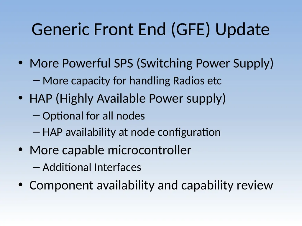
slide5. Generic Front End (GFE) Update More Powerful SPS (Switching Power Supply)
More capacity for handling Radios etc
HAP (Highly Available Power supply)
Optional for all nodes
HAP availability at node configuration
More capable microcontroller
Additional Interfaces
Component availability and capability review<br>
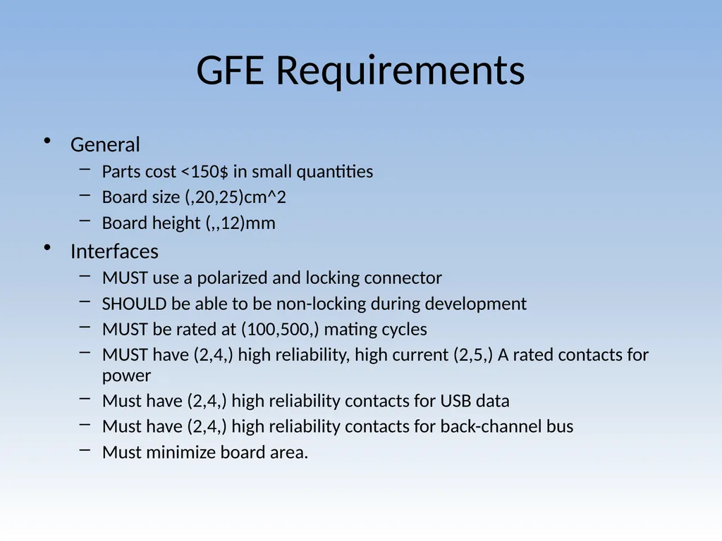
slide6. GFE Requirements General
Parts cost <150$ in small quantities
Board size (,20,25)cm^2
Board height (,,12)mm
Interfaces
MUST use a polarized and locking connector
SHOULD be able to be non-locking during development
MUST be rated at (100,500,) mating cycles
MUST have (2,4,) high reliability, high current (2,5,) A rated contacts for power
Must have (2,4,) high reliability contacts for USB data
Must have (2,4,) high reliability contacts for back-channel bus
Must minimize board area.<br>
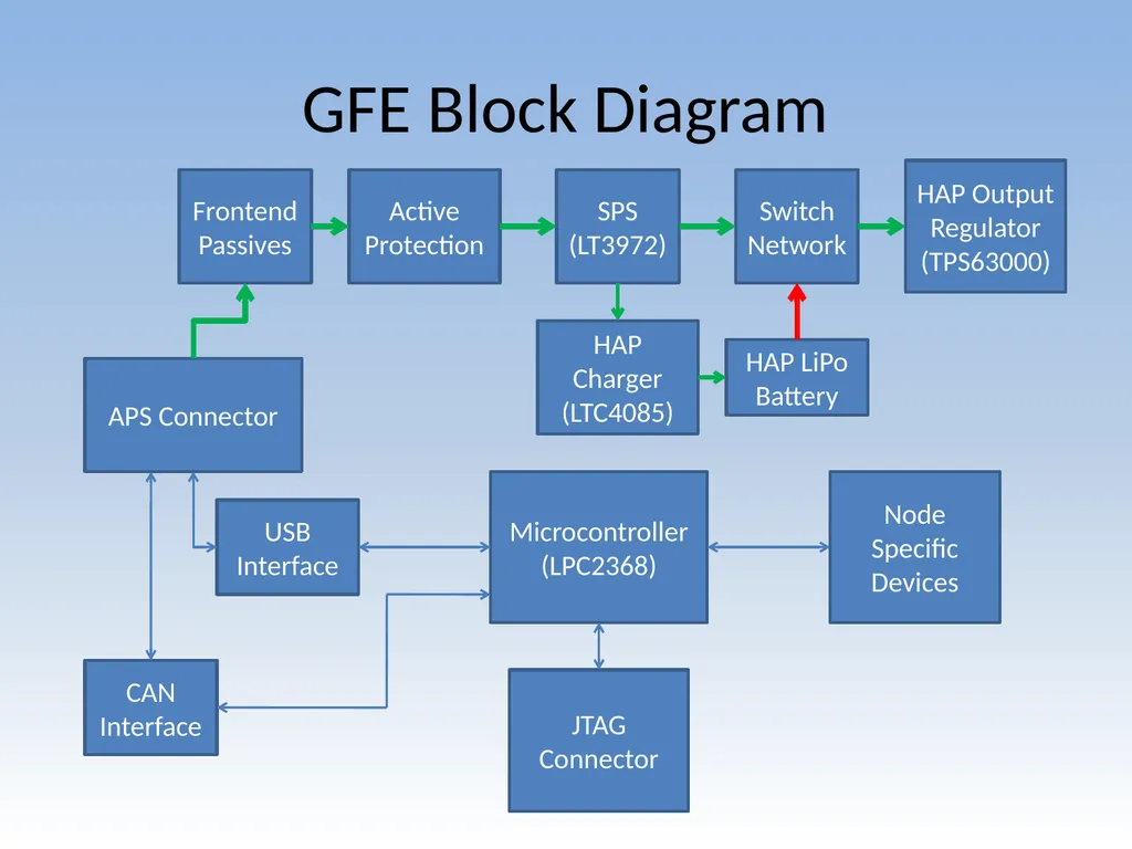
slide7. GFE Block Diagram APS Connector Frontend Passives Active Protection SPS (LT3972) HAP Charger (LTC4085) HAP LiPo Battery HAP Output Regulator (TPS63000) USB Interface CAN Interface JTAG Connector Microcontroller
(LPC2368) Node Specific Devices Switch Network<br>
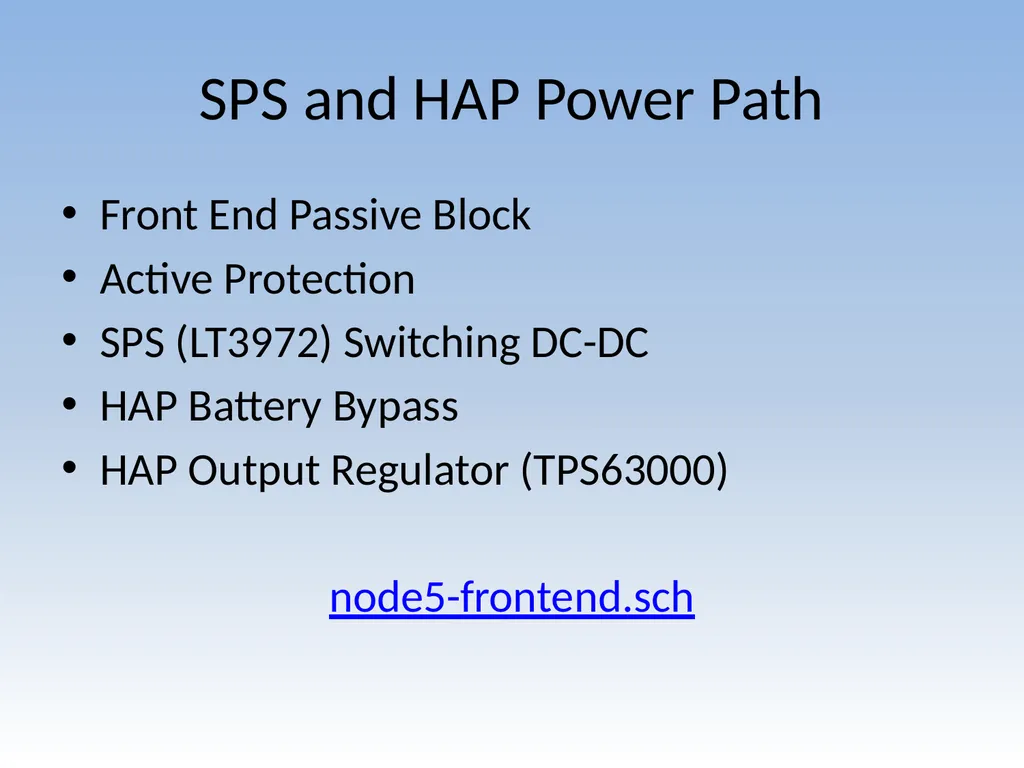
slide8. SPS and HAP Power Path Front End Passive Block
Active Protection
SPS (LT3972) Switching DC-DC
HAP Battery Bypass
HAP Output Regulator (TPS63000)
node5-frontend.sch<br>
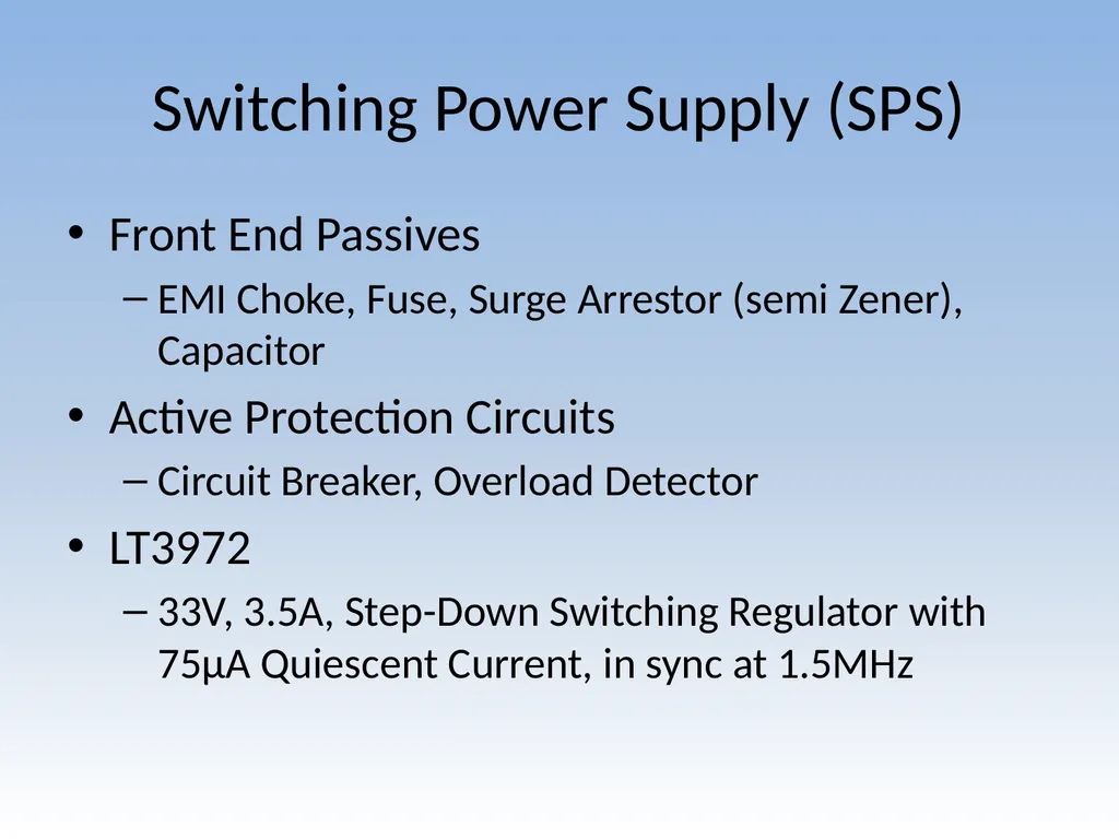
slide9. Switching Power Supply (SPS) Front End Passives
EMI Choke, Fuse, Surge Arrestor (semi Zener), Capacitor
Active Protection Circuits
Circuit Breaker, Overload Detector
LT3972
33V, 3.5A, Step-Down Switching Regulator with 75μA Quiescent Current, in sync at 1.5MHz<br>
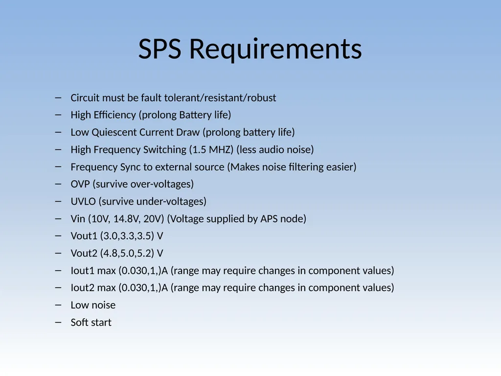
slide10. SPS Requirements Circuit must be fault tolerant/resistant/robust
High Efficiency (prolong Battery life)
Low Quiescent Current Draw (prolong battery life)
High Frequency Switching (1.5 MHZ) (less audio noise)
Frequency Sync to external source (Makes noise filtering easier)
OVP (survive over-voltages)
UVLO (survive under-voltages)
Vin (10V, 14.8V, 20V) (Voltage supplied by APS node)
Vout1 (3.0,3.3,3.5) V
Vout2 (4.8,5.0,5.2) V
Iout1 max (0.030,1,)A (range may require changes in component values)
Iout2 max (0.030,1,)A (range may require changes in component values)
Low noise
Soft start<br>
slide11. Highly Available Power Supply (HAP) Charger IC (LTC4085)
Battery (450mAh)
Mosfet Switch and Ideal Diode
Output Regulator (TPS63000)<br>
slide12. HAP Requirements MUST use single Li Ion Polymer cell
MUST have a seamless transition from externally powered to battery-powered
MUST meet standard lithium charge/discharge safety requirements (thermal, voltage, current, time, fuse)
MUST store enough power to run generic node for (1,4,) hours (Pyro requirement)
MUST be able to be unpopulated on board (for most nodes)
MUST be able to measure battery voltage
MUST be able to have external charge control (from microcontroller)<br>
slide13. Microcontroller (LPC2368) Differences from Old to New
Number of Node configurable GPIO available
Busses Available
Memory and Processing Speed<br>
slide14. Microcontroller Requirements MUST use a LPC2xxx series microcontroller
MUST have USB and back-channel peripherals
MUST have (32,64,) K RAM
MUST use 12 MHz crystal (for USB) and PLL to highest Freq.<br>
slide15. Interfacing GFE (GPIO and Analog Connections)
Connections to onboard GFE devices
CAN (Controller Area Network)
Primarily used for off-board communications
USB (Universal Serial Bus)
Primarily used for off-board communications
SPI (Serial Peripheral Interface)
Used for communication to on board devices
I2C (Inter-Integrated Circuit Bus)
Used for communication to on board devices
1 Wire (One Wire)
Used for communication to onboard devices
Analog
Onboard A/D and D/A pins are available<br>
slide16. Hurdles Datasheet Contents and Research
Component Tracking during research
Rejected list
Modeling
Missing LT-Spice models
Models that don’t match reference designs
Component Packages
Eagle Schematics, Libraries, Layout
GIT and other Open Source Software<br>
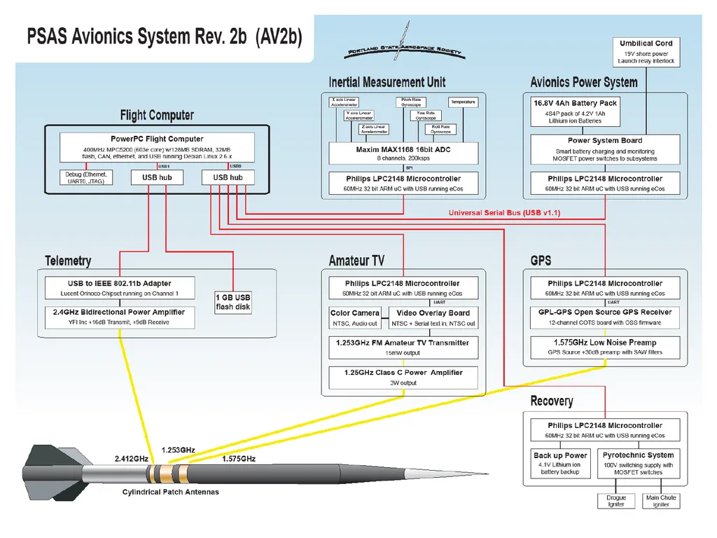
slide18. Avionics Power System An Overview<br>
slide19. APS Key Functions Distribute Battery/Shore power to all other rocket nodes via a network of power switches
Provide a means of control over which nodes receive power
Provide over current protection to downstream devices
Distribute data signals to attached devices via power switch connectors<br>
slide20. APS Key Functions Umbilical Shore Power connection
Simultaneously charges the APS battery and provides power to the rocket systems during charging
Provides an avenue for communication between land based computer and APS system
Provides a “launch-detect” signal which indicates that launch has occurred<br>
slide21. APS Key Functions USB Hub
Distributes USB data to downstream devices via power switch connectors
Configurable for low, full and high speed USB differential signaling<br>
slide22. APS Power Switches Power Distribution, Protection and Control<br>
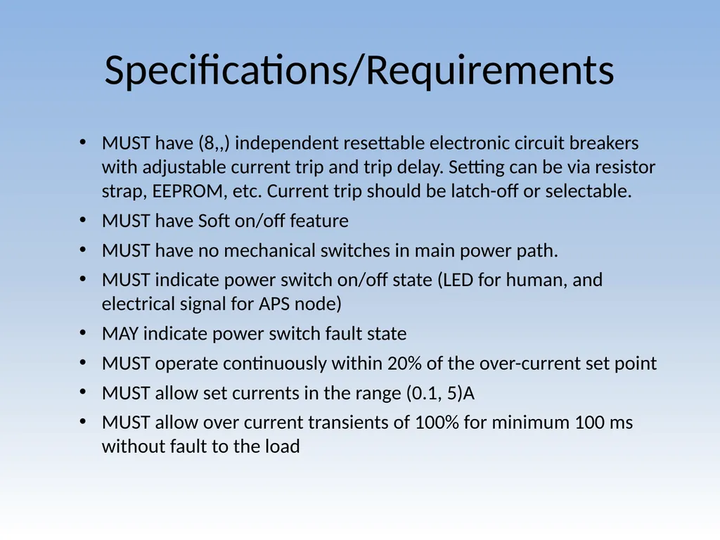
slide23. Specifications/Requirements MUST have (8,,) independent resettable electronic circuit breakers with adjustable current trip and trip delay. Setting can be via resistor strap, EEPROM, etc. Current trip should be latch-off or selectable.
MUST have Soft on/off feature
MUST have no mechanical switches in main power path.
MUST indicate power switch on/off state (LED for human, and electrical signal for APS node)
MAY indicate power switch fault state
MUST operate continuously within 20% of the over-current set point
MUST allow set currents in the range (0.1, 5)A
MUST allow over current transients of 100% for minimum 100 ms without fault to the load<br>
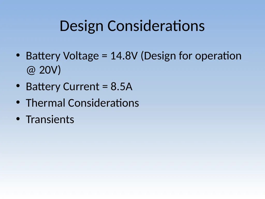
slide24. Design Considerations Battery Voltage = 14.8V (Design for operation @ 20V)
Battery Current = 8.5A
Thermal Considerations
Transients<br>
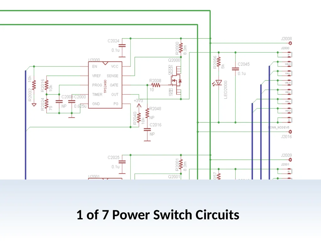
slide25. 1 of 7 Power Switch Circuits<br>
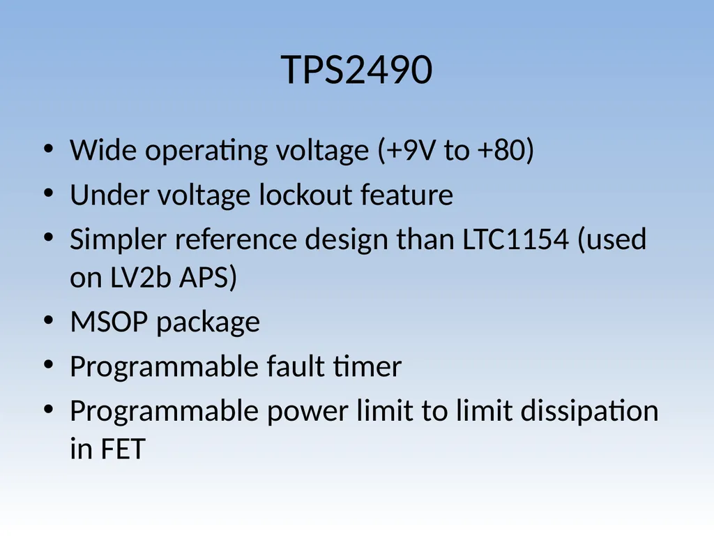
slide26. TPS2490 Wide operating voltage (+9V to +80)
Under voltage lockout feature
Simpler reference design than LTC1154 (used on LV2b APS)
MSOP package
Programmable fault timer
Programmable power limit to limit dissipation in FET<br>
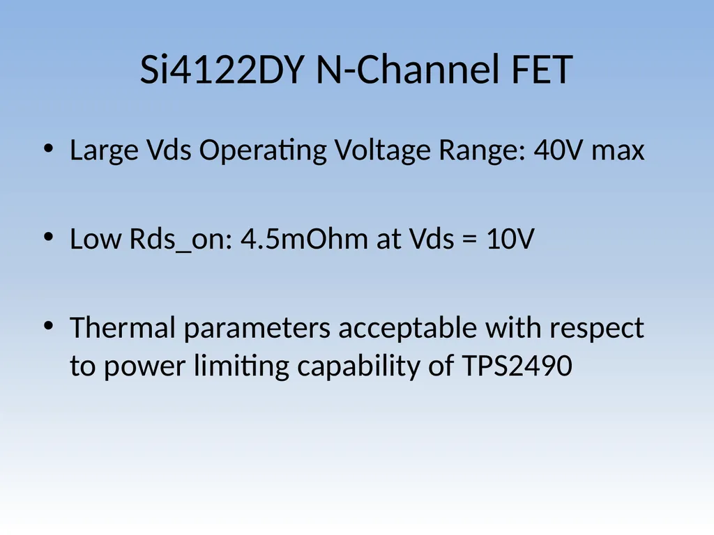
slide27. Si4122DY N-Channel FET Large Vds Operating Voltage Range: 40V max
Low Rds_on: 4.5mOhm at Vds = 10V
Thermal parameters acceptable with respect to power limiting capability of TPS2490<br>
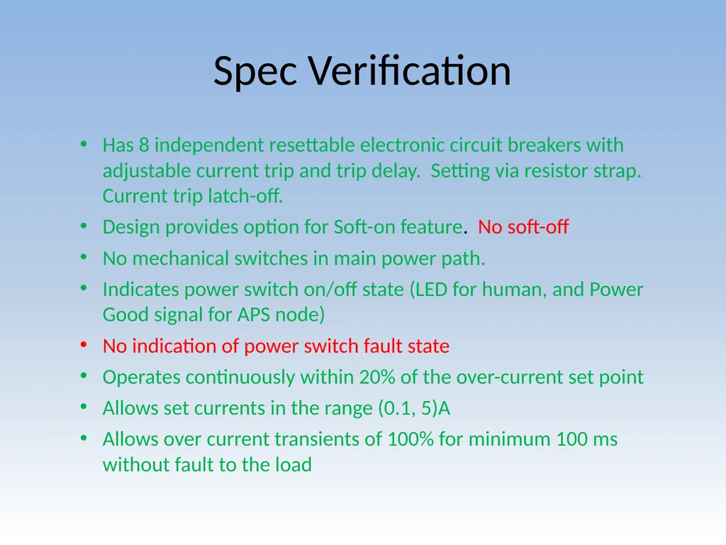
slide28. Spec Verification Has 8 independent resettable electronic circuit breakers with adjustable current trip and trip delay. Setting via resistor strap. Current trip latch-off.
Design provides option for Soft-on feature. No soft-off
No mechanical switches in main power path.
Indicates power switch on/off state (LED for human, and Power Good signal for APS node)
No indication of power switch fault state
Operates continuously within 20% of the over-current set point
Allows set currents in the range (0.1, 5)A
Allows over current transients of 100% for minimum 100 ms without fault to the load<br>
slide29. USB Hub USB Data Distribution<br>
slide30. Specifications/Requirements SHOULD be USB 2.0 compliant High Speed (480 Mbps)
MUST handle (8,,) downstream devices (devices may be further hubs)
SHOULD have hub status LEDs<br>
slide31. Design Considerations Hub requires 3.3V power supply
Default configuration settings
Interface with micro-controller for changing configuration settings<br>
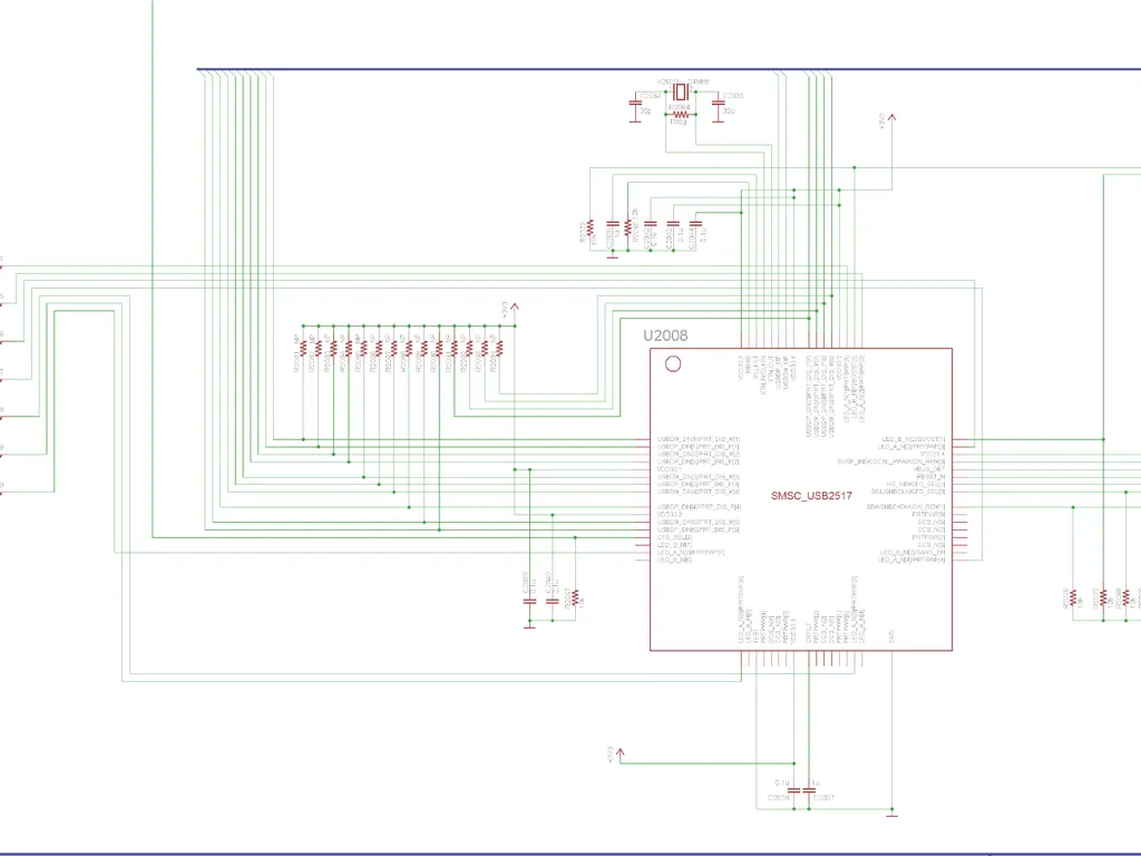
slide33. SMSC-USB2517 Requires 3.3V Power Supply
64-pin QFN package (smaller than 2507 IC)
Large number of configuration options
Compliant with USB 2.0 low, full and high speed
Control over configuration options provided to the ARM microprocessor<br>
slide34. Default Configuration CFG_SEL Pins = ‘000’ Strap options enabled
Self-power option enabled
LED mode = speed
Individual power switching
Individual over-current sensing<br>
slide35. Configuration Strapping Options PHY_BOOST[1:0]
Allows signals to upstream devices be boosted to 4%, 8% or 12%.
Default – No Boost (PHY_BOOSY[1:0]=‘00’)
NON_REM[2:0]
These pins determine which downstream devices will be considered removable
Default – All devices set as removable (NON_REM[2:0] = ‘000’<br>
slide36. Spec. Verification USB 2.0 compliant for Low Speed, Full Speed and High Speed (480 Mbps)
Handles 7 downstream devices (devices may be further hubs)
Has hub status LEDs which also indicate speed of attached devices<br>
slide37. Umbilical Connection Connecting the Rocket to the Ground Computer<br>
slide38. Specifications/Requirements MUST seamlessly shift between shore power and battery power
MUST be able to detect the presence of shore power
MUST wake up APS microcontroller if shore power turned on
MUST be able to sense if connector is inserted or removed (launch detect)<br>
slide39. Design Considerations Connector type
Ideal Diode (No longer used)
Launch detect implementation<br>
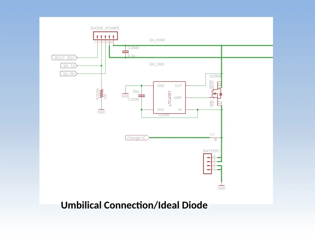
slide40. Umbilical Connection/Ideal Diode<br>
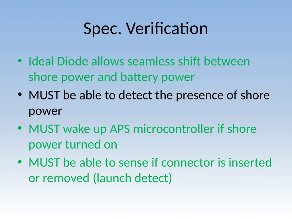
slide41. Spec. Verification Ideal Diode allows seamless shift between shore power and battery power
MUST be able to detect the presence of shore power
MUST wake up APS microcontroller if shore power turned on
MUST be able to sense if connector is inserted or removed (launch detect)<br>
slide42. Summary APS Power Switch Network
USB Hub
Umbilical Connection to APS (Not Implemented)<br>
slide44. Battery and Charging Systems<br>
slide45. Battery Battery requirements
SHOULD be a 4-series cell Li battery
Battery SHOULD cost <500$
Overall Battery SHOULD have energy-mass density (100,,) W.hr/kg
Overall Battery energy-volume density SHOULD be (200,,) W.hr/l
Battery capacity SHOULD be (4,8,) AHr (TODO: TBD on new power budget)
SHOULD have dimensions less than (,3.0,3.5) inches in the cross sectional plane of the airframe, length (,,10)inches
MUST have a fuse in the pack before the lead
Total battery "unplugged" leakage MUST be < C/(1,5,) year rate (e.g. ~ 100 uA for 4 AHr)<br>
slide46. Charger Requirements:
MUST meet standard lithium charge/discharge safety requirements (thermal, voltage, current, time, fuse)
MUST be able to charge at (,1C,C/2) rates at internal air temperature of 50 deg C.*
MAY equalize cells up to some small bypass power (e.g., .5W)
MUST indicate charging status (on/off)
MAY indicate some kind of charge % (blink rate, color, LED bar graph, etc)<br>
slide47. Internal Charger Apscharger2.sch<br>
slide48. External charger APSEXTERNALCHARGER.sch<br>
slide49. Issues Labeling of design sections
Changes in design<br>
slide51. Main tasks: Analog pressure sensor
7-port USB hub controller
Battery sensor<br>
slide52. Analog pressure sensor Reason to redesign:
The pressure sensor that is currently used is SCP1000. Its measuring range is from 30 kPa to 120 kPa.
We want to find a pressure sensor that can accurately measure the pressure from 1 atm down to 0 atm.<br>
slide53. Analog pressure sensor Requirements:
MUST have pressure range of 0 - 1 ATM (0 kPa - ~115 kPa, 0 - ~15 PSI) or more
Absolute pressure (needs onboard reference)
SHOULD use (,3.3,5) V power supply
SHOULD use (,10,50) mA current
SHOULD have single ended analog output OR digital output
MAY have quick response time < 1 ms (~ KHz of bandwidth)
MUST have a small package size (0,1,10) cm3<br>
slide54. Analog pressure sensor ASDX DO series:
Pressure range from 0 psi to 15 psi (1 psi = 6.9 kPa)
Available in absolute, differential and gage types.
A single 5.0 Vdc supply
The output of the device is a corrected pressure value in hex format with 12-bit resolution. Therefore, the smallest change in the output given any change in pressure is 5V/(2^12) = 1.22 mV
Response time of 8ms.<br>
slide55. Analog pressure sensor Pressure Sensor Test
Goal: To test pressure sensors to near vacuum and outside their usual acceleration and temperature ranges. Those sensors are:
Honeywell ASDX015A24R
Freescale MP3H6115A
VTI SCP1000<br>
slide56. Giant vacuum chamber in Dr. Erik Sanchez's lab at PSU in Science Building Reference: http://psas.pdx.edu/avionics/pressure_sensor_testing/<br>
slide57. Analog pressure sensor Result:
The SCP sensor was accurately reflecting the pressure recorded on the pressure gauge, even down to 0.45 kPa.
ASDX worked down to 0.45 kPa as expected.
The MP3 bottomed out due to hitting the ground rail at ~ 10 kPa<br>
slide58. USB Hub controller Requirements:
One up stream, seven down streams
Small
Powered
High speed
Available<br>
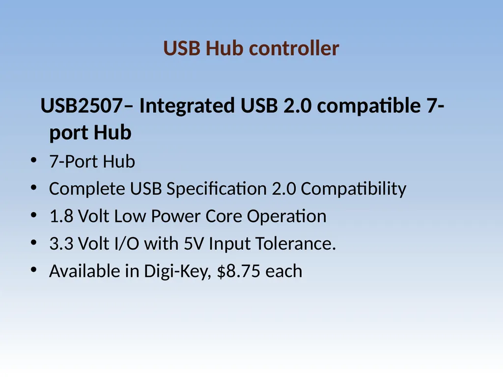
slide59. USB Hub controller USB2507– Integrated USB 2.0 compatible 7-port Hub
7-Port Hub
Complete USB Specification 2.0 Compatibility
1.8 Volt Low Power Core Operation
3.3 Volt I/O with 5V Input Tolerance.
Available in Digi-Key, $8.75 each<br>
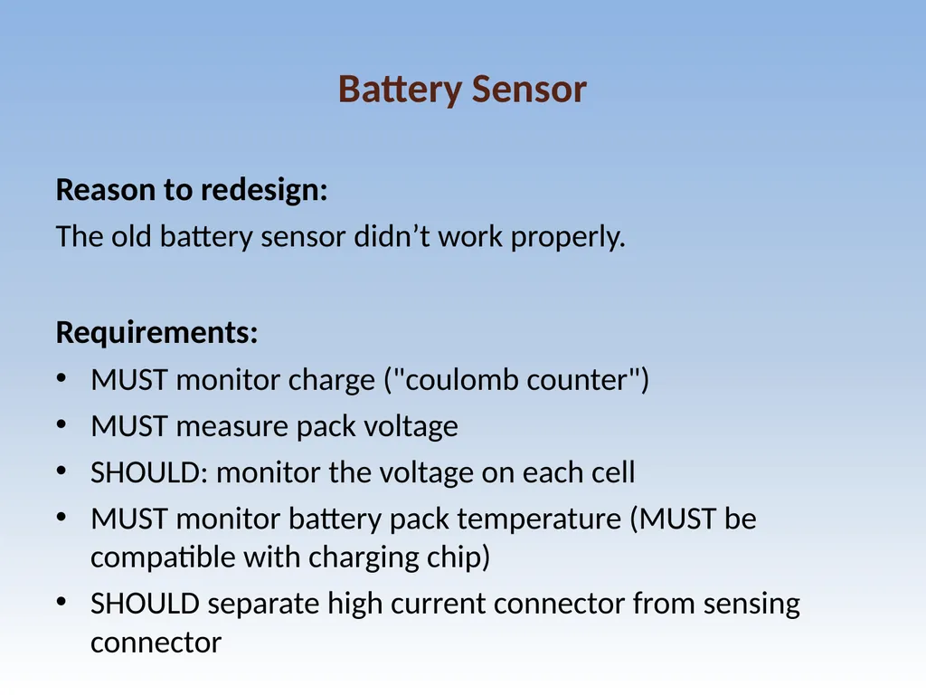
slide60. Battery Sensor Reason to redesign:
The old battery sensor didn’t work properly.
Requirements:
MUST monitor charge ("coulomb counter")
MUST measure pack voltage
SHOULD: monitor the voltage on each cell
MUST monitor battery pack temperature (MUST be compatible with charging chip)
SHOULD separate high current connector from sensing connector<br>
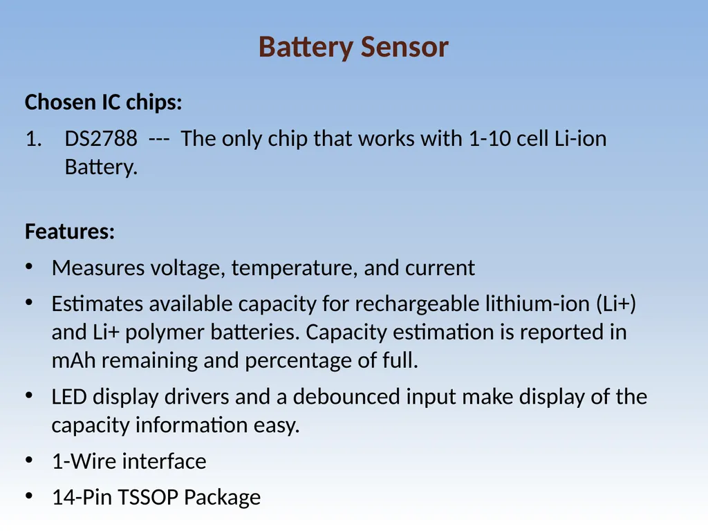
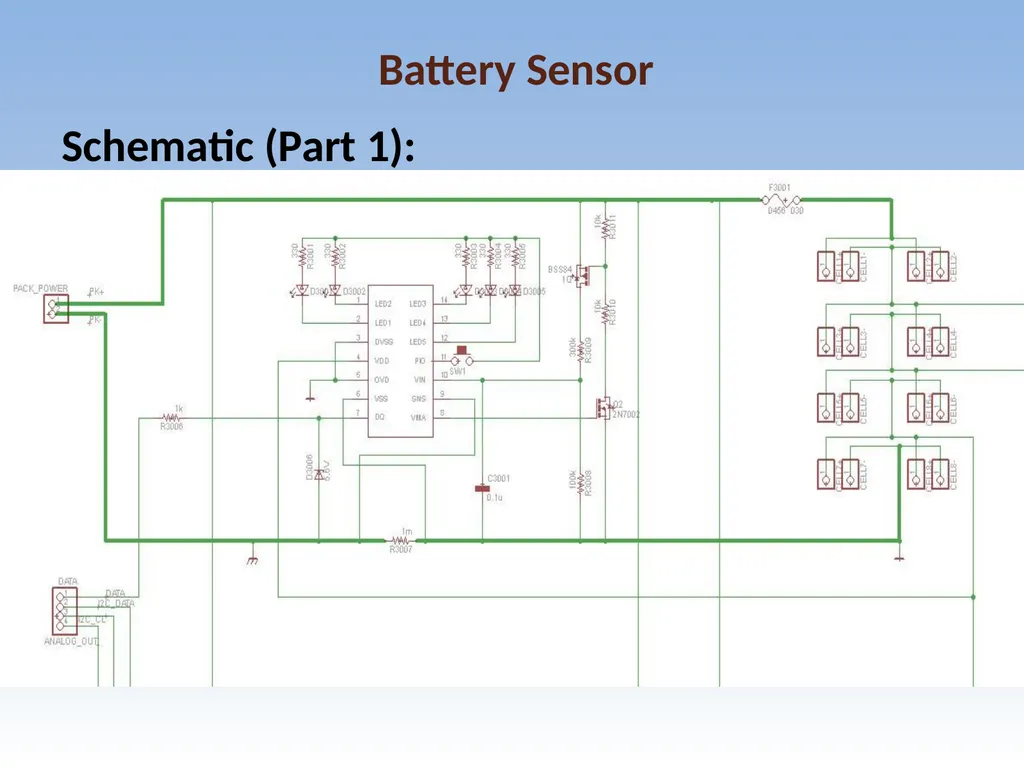
slide61. Battery Sensor Chosen IC chips:
DS2788 --- The only chip that works with 1-10 cell Li-ion Battery.
Features:
Measures voltage, temperature, and current
Estimates available capacity for rechargeable lithium-ion (Li+) and Li+ polymer batteries. Capacity estimation is reported in mAh remaining and percentage of full.
LED display drivers and a debounced input make display of the capacity information easy.
1-Wire interface
14-Pin TSSOP Package<br>
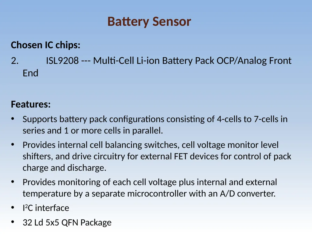
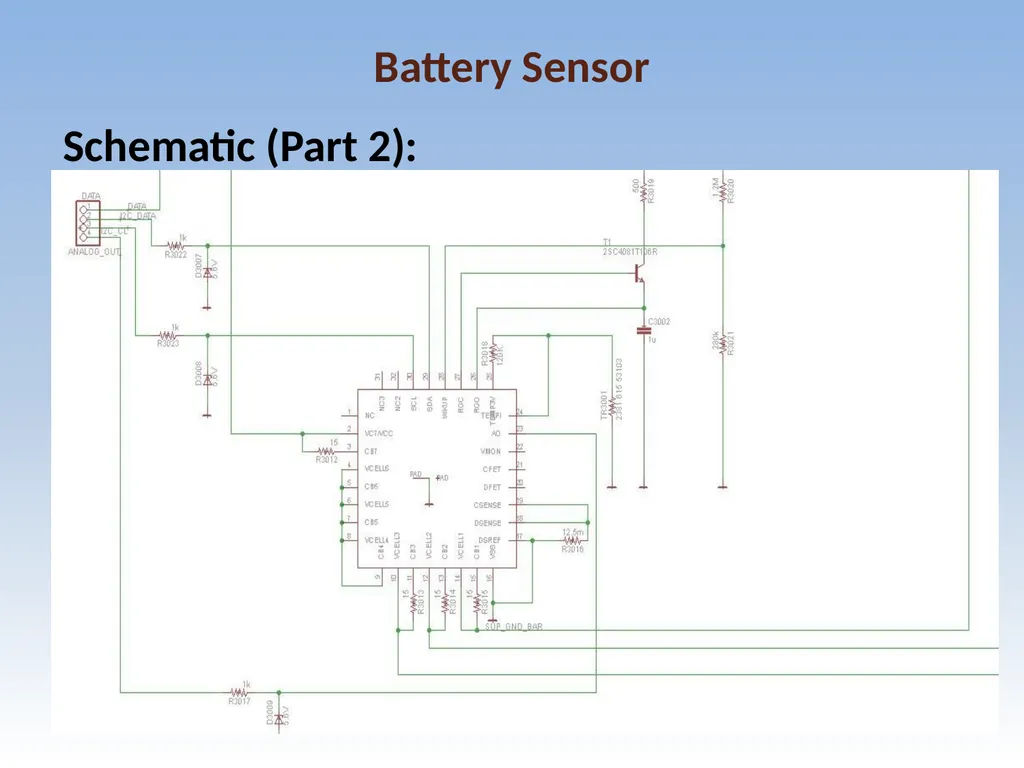
slide62. Battery Sensor Chosen IC chips:
2. ISL9208 --- Multi-Cell Li-ion Battery Pack OCP/Analog Front End
Features:
Supports battery pack configurations consisting of 4-cells to 7-cells in series and 1 or more cells in parallel.
Provides internal cell balancing switches, cell voltage monitor level shifters, and drive circuitry for external FET devices for control of pack charge and discharge.
Provides monitoring of each cell voltage plus internal and external temperature by a separate microcontroller with an A/D converter.
I2C interface
32 Ld 5x5 QFN Package<br>
slide63. Battery Sensor Schematic (Part 1):<br>
slide64. Battery Sensor Schematic (Part 2):<br>
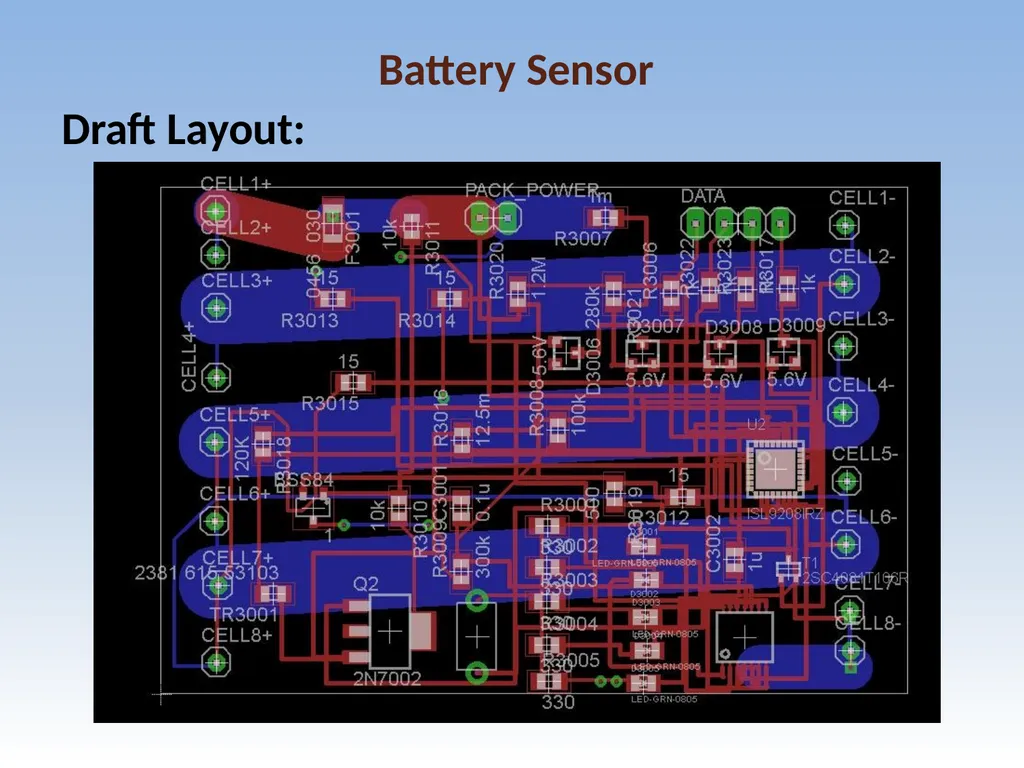
slide65. Battery Sensor Draft Layout:<br>
slide67. Firmware<br>
slide68. Objectives Create firmware to run the APS and all its peripherals.
Real time data collection and response
Design for graceful/safe failure modes
Maintain modularity to allow for code re-use in other nodes where possible<br>
slide69. Objectives Power switching to various subsystems
Battery Management
Umbilical disconnect detection
Error Handling and Logging
Serial console / UART based control interface<br>
slide70. The nodes were to be standardized on the LPC2368 (ARM7TDMI-S) microcontroller
They were to run FreeRTOS for multitasking / task management support
Communication with peripherals and other nodes was to use the following interfaces:
CAN USB UART 1-Wire
SPI I2C Analog GPIO Objectives<br>
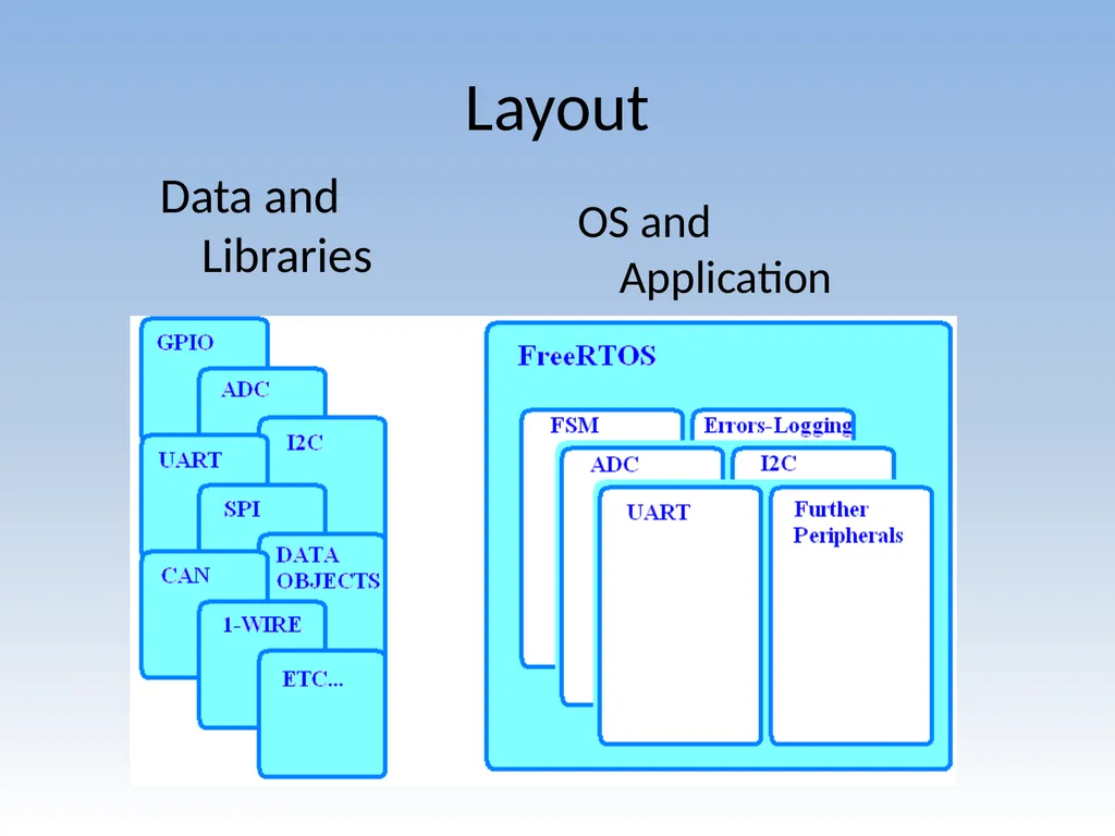
slide71. Layout Application divided into many tasks
Tasks grouped by function or interface
Tasks can act as “gatekeepers” to interfaces, or prioritize resource consumption<br>
slide72. Layout Data and Libraries OS and Application<br>
slide73. Overcoming Hurdles Configuration of Linux system
Setting up a cross-compiler
Getting compiled code on the OLIMEX boards
Tools for collaboration - Git
Uncertainty and error messages – help!<br>
slide74. Scope of project
Far broader than it initially appeared
Unfamiliarity with development environment
Linux
Git
Issues programming via JTAG
Board in “hung” state
Burning JTAG ports Overcoming Hurdles<br>
slide75. The Switch to LPC 2378 New processor - New version of FreeRTOS
More functionality
Significantly different physical pin setup
Code changes needed
Register initialization
New built in devices/additional ports
Significantly changed FreeRTOS API Overcoming Hurdles<br>
slide76. Accomplishments GPIO handling
Simple commands to enable, read and write
Multi-Channel ADC
All ports and channels available
Simple commands to enable, read and write LPC2148<br>
slide77. Accomplishments SPI
Interface suite created
Device specific drivers created
UART control framework
Acts on commands via UART
Tested to respond to correct input only LPC2148<br>
slide78. Accomplishments Error Handling/Logging
Stores sequential list of errors
Reports list of errors and statistics
Uses UART control framework
I2C (functional outline / algorithms)
Behavior defined for operation of Master states LPC2148<br>
slide79. Accomplishments Vibration and Vacuum Chamber tests
Development board - LPC 2148
SCP1000 pressure sensor (High Speed SPI)
ASDX pressure sensor (analog)
Additional analog sensors Sensor Testing<br>
slide80. Accomplishments GPIO Handling
Additional Ports and Pins!
Ports and Pins available per processor type
Multi-Channel ADC
Single port (fewer total channels!) LPC2368/78<br>
slide81. Accomplishments UART control framework
Acts on commands via UART
FSM (APS specific)
Sleep, Wake, Safe, Armed
Critical inputs determine whether to change state
State sub-functions will perform internal tasks LPC2368/78<br>
Ai Ling Chen, David Loupin, Jeremy Booth, Ken Zeigler, Mike Engstrom, Scott Schuehle Academic Advisor
Allen Taylor PSAS Advisors
Andrew and Tim<br>
slide3. Team Member Responsibilities: Ken: GFE, SPS, HAP, Microprocessor
Scott: Power Switches, USB Hub, Umbilical
David: Battery and Charging Systems
Ai Ling: Pressure & Battery Sensors, USB Hub
Firmware: Mike, Jeremy Avionics Power System (APS)<br>
slide5. Generic Front End (GFE) Update More Powerful SPS (Switching Power Supply)
More capacity for handling Radios etc
HAP (Highly Available Power supply)
Optional for all nodes
HAP availability at node configuration
More capable microcontroller
Additional Interfaces
Component availability and capability review<br>
slide6. GFE Requirements General
Parts cost <150$ in small quantities
Board size (,20,25)cm^2
Board height (,,12)mm
Interfaces
MUST use a polarized and locking connector
SHOULD be able to be non-locking during development
MUST be rated at (100,500,) mating cycles
MUST have (2,4,) high reliability, high current (2,5,) A rated contacts for power
Must have (2,4,) high reliability contacts for USB data
Must have (2,4,) high reliability contacts for back-channel bus
Must minimize board area.<br>
slide7. GFE Block Diagram APS Connector Frontend Passives Active Protection SPS (LT3972) HAP Charger (LTC4085) HAP LiPo Battery HAP Output Regulator (TPS63000) USB Interface CAN Interface JTAG Connector Microcontroller
(LPC2368) Node Specific Devices Switch Network<br>
slide8. SPS and HAP Power Path Front End Passive Block
Active Protection
SPS (LT3972) Switching DC-DC
HAP Battery Bypass
HAP Output Regulator (TPS63000)
node5-frontend.sch<br>
slide9. Switching Power Supply (SPS) Front End Passives
EMI Choke, Fuse, Surge Arrestor (semi Zener), Capacitor
Active Protection Circuits
Circuit Breaker, Overload Detector
LT3972
33V, 3.5A, Step-Down Switching Regulator with 75μA Quiescent Current, in sync at 1.5MHz<br>
slide10. SPS Requirements Circuit must be fault tolerant/resistant/robust
High Efficiency (prolong Battery life)
Low Quiescent Current Draw (prolong battery life)
High Frequency Switching (1.5 MHZ) (less audio noise)
Frequency Sync to external source (Makes noise filtering easier)
OVP (survive over-voltages)
UVLO (survive under-voltages)
Vin (10V, 14.8V, 20V) (Voltage supplied by APS node)
Vout1 (3.0,3.3,3.5) V
Vout2 (4.8,5.0,5.2) V
Iout1 max (0.030,1,)A (range may require changes in component values)
Iout2 max (0.030,1,)A (range may require changes in component values)
Low noise
Soft start<br>
slide11. Highly Available Power Supply (HAP) Charger IC (LTC4085)
Battery (450mAh)
Mosfet Switch and Ideal Diode
Output Regulator (TPS63000)<br>
slide12. HAP Requirements MUST use single Li Ion Polymer cell
MUST have a seamless transition from externally powered to battery-powered
MUST meet standard lithium charge/discharge safety requirements (thermal, voltage, current, time, fuse)
MUST store enough power to run generic node for (1,4,) hours (Pyro requirement)
MUST be able to be unpopulated on board (for most nodes)
MUST be able to measure battery voltage
MUST be able to have external charge control (from microcontroller)<br>
slide13. Microcontroller (LPC2368) Differences from Old to New
Number of Node configurable GPIO available
Busses Available
Memory and Processing Speed<br>
slide14. Microcontroller Requirements MUST use a LPC2xxx series microcontroller
MUST have USB and back-channel peripherals
MUST have (32,64,) K RAM
MUST use 12 MHz crystal (for USB) and PLL to highest Freq.<br>
slide15. Interfacing GFE (GPIO and Analog Connections)
Connections to onboard GFE devices
CAN (Controller Area Network)
Primarily used for off-board communications
USB (Universal Serial Bus)
Primarily used for off-board communications
SPI (Serial Peripheral Interface)
Used for communication to on board devices
I2C (Inter-Integrated Circuit Bus)
Used for communication to on board devices
1 Wire (One Wire)
Used for communication to onboard devices
Analog
Onboard A/D and D/A pins are available<br>
slide16. Hurdles Datasheet Contents and Research
Component Tracking during research
Rejected list
Modeling
Missing LT-Spice models
Models that don’t match reference designs
Component Packages
Eagle Schematics, Libraries, Layout
GIT and other Open Source Software<br>
slide18. Avionics Power System An Overview<br>
slide19. APS Key Functions Distribute Battery/Shore power to all other rocket nodes via a network of power switches
Provide a means of control over which nodes receive power
Provide over current protection to downstream devices
Distribute data signals to attached devices via power switch connectors<br>
slide20. APS Key Functions Umbilical Shore Power connection
Simultaneously charges the APS battery and provides power to the rocket systems during charging
Provides an avenue for communication between land based computer and APS system
Provides a “launch-detect” signal which indicates that launch has occurred<br>
slide21. APS Key Functions USB Hub
Distributes USB data to downstream devices via power switch connectors
Configurable for low, full and high speed USB differential signaling<br>
slide22. APS Power Switches Power Distribution, Protection and Control<br>
slide23. Specifications/Requirements MUST have (8,,) independent resettable electronic circuit breakers with adjustable current trip and trip delay. Setting can be via resistor strap, EEPROM, etc. Current trip should be latch-off or selectable.
MUST have Soft on/off feature
MUST have no mechanical switches in main power path.
MUST indicate power switch on/off state (LED for human, and electrical signal for APS node)
MAY indicate power switch fault state
MUST operate continuously within 20% of the over-current set point
MUST allow set currents in the range (0.1, 5)A
MUST allow over current transients of 100% for minimum 100 ms without fault to the load<br>
slide24. Design Considerations Battery Voltage = 14.8V (Design for operation @ 20V)
Battery Current = 8.5A
Thermal Considerations
Transients<br>
slide25. 1 of 7 Power Switch Circuits<br>
slide26. TPS2490 Wide operating voltage (+9V to +80)
Under voltage lockout feature
Simpler reference design than LTC1154 (used on LV2b APS)
MSOP package
Programmable fault timer
Programmable power limit to limit dissipation in FET<br>
slide27. Si4122DY N-Channel FET Large Vds Operating Voltage Range: 40V max
Low Rds_on: 4.5mOhm at Vds = 10V
Thermal parameters acceptable with respect to power limiting capability of TPS2490<br>
slide28. Spec Verification Has 8 independent resettable electronic circuit breakers with adjustable current trip and trip delay. Setting via resistor strap. Current trip latch-off.
Design provides option for Soft-on feature. No soft-off
No mechanical switches in main power path.
Indicates power switch on/off state (LED for human, and Power Good signal for APS node)
No indication of power switch fault state
Operates continuously within 20% of the over-current set point
Allows set currents in the range (0.1, 5)A
Allows over current transients of 100% for minimum 100 ms without fault to the load<br>
slide29. USB Hub USB Data Distribution<br>
slide30. Specifications/Requirements SHOULD be USB 2.0 compliant High Speed (480 Mbps)
MUST handle (8,,) downstream devices (devices may be further hubs)
SHOULD have hub status LEDs<br>
slide31. Design Considerations Hub requires 3.3V power supply
Default configuration settings
Interface with micro-controller for changing configuration settings<br>
slide33. SMSC-USB2517 Requires 3.3V Power Supply
64-pin QFN package (smaller than 2507 IC)
Large number of configuration options
Compliant with USB 2.0 low, full and high speed
Control over configuration options provided to the ARM microprocessor<br>
slide34. Default Configuration CFG_SEL Pins = ‘000’ Strap options enabled
Self-power option enabled
LED mode = speed
Individual power switching
Individual over-current sensing<br>
slide35. Configuration Strapping Options PHY_BOOST[1:0]
Allows signals to upstream devices be boosted to 4%, 8% or 12%.
Default – No Boost (PHY_BOOSY[1:0]=‘00’)
NON_REM[2:0]
These pins determine which downstream devices will be considered removable
Default – All devices set as removable (NON_REM[2:0] = ‘000’<br>
slide36. Spec. Verification USB 2.0 compliant for Low Speed, Full Speed and High Speed (480 Mbps)
Handles 7 downstream devices (devices may be further hubs)
Has hub status LEDs which also indicate speed of attached devices<br>
slide37. Umbilical Connection Connecting the Rocket to the Ground Computer<br>
slide38. Specifications/Requirements MUST seamlessly shift between shore power and battery power
MUST be able to detect the presence of shore power
MUST wake up APS microcontroller if shore power turned on
MUST be able to sense if connector is inserted or removed (launch detect)<br>
slide39. Design Considerations Connector type
Ideal Diode (No longer used)
Launch detect implementation<br>
slide40. Umbilical Connection/Ideal Diode<br>
slide41. Spec. Verification Ideal Diode allows seamless shift between shore power and battery power
MUST be able to detect the presence of shore power
MUST wake up APS microcontroller if shore power turned on
MUST be able to sense if connector is inserted or removed (launch detect)<br>
slide42. Summary APS Power Switch Network
USB Hub
Umbilical Connection to APS (Not Implemented)<br>
slide44. Battery and Charging Systems<br>
slide45. Battery Battery requirements
SHOULD be a 4-series cell Li battery
Battery SHOULD cost <500$
Overall Battery SHOULD have energy-mass density (100,,) W.hr/kg
Overall Battery energy-volume density SHOULD be (200,,) W.hr/l
Battery capacity SHOULD be (4,8,) AHr (TODO: TBD on new power budget)
SHOULD have dimensions less than (,3.0,3.5) inches in the cross sectional plane of the airframe, length (,,10)inches
MUST have a fuse in the pack before the lead
Total battery "unplugged" leakage MUST be < C/(1,5,) year rate (e.g. ~ 100 uA for 4 AHr)<br>
slide46. Charger Requirements:
MUST meet standard lithium charge/discharge safety requirements (thermal, voltage, current, time, fuse)
MUST be able to charge at (,1C,C/2) rates at internal air temperature of 50 deg C.*
MAY equalize cells up to some small bypass power (e.g., .5W)
MUST indicate charging status (on/off)
MAY indicate some kind of charge % (blink rate, color, LED bar graph, etc)<br>
slide47. Internal Charger Apscharger2.sch<br>
slide48. External charger APSEXTERNALCHARGER.sch<br>
slide49. Issues Labeling of design sections
Changes in design<br>
slide51. Main tasks: Analog pressure sensor
7-port USB hub controller
Battery sensor<br>
slide52. Analog pressure sensor Reason to redesign:
The pressure sensor that is currently used is SCP1000. Its measuring range is from 30 kPa to 120 kPa.
We want to find a pressure sensor that can accurately measure the pressure from 1 atm down to 0 atm.<br>
slide53. Analog pressure sensor Requirements:
MUST have pressure range of 0 - 1 ATM (0 kPa - ~115 kPa, 0 - ~15 PSI) or more
Absolute pressure (needs onboard reference)
SHOULD use (,3.3,5) V power supply
SHOULD use (,10,50) mA current
SHOULD have single ended analog output OR digital output
MAY have quick response time < 1 ms (~ KHz of bandwidth)
MUST have a small package size (0,1,10) cm3<br>
slide54. Analog pressure sensor ASDX DO series:
Pressure range from 0 psi to 15 psi (1 psi = 6.9 kPa)
Available in absolute, differential and gage types.
A single 5.0 Vdc supply
The output of the device is a corrected pressure value in hex format with 12-bit resolution. Therefore, the smallest change in the output given any change in pressure is 5V/(2^12) = 1.22 mV
Response time of 8ms.<br>
slide55. Analog pressure sensor Pressure Sensor Test
Goal: To test pressure sensors to near vacuum and outside their usual acceleration and temperature ranges. Those sensors are:
Honeywell ASDX015A24R
Freescale MP3H6115A
VTI SCP1000<br>
slide56. Giant vacuum chamber in Dr. Erik Sanchez's lab at PSU in Science Building Reference: http://psas.pdx.edu/avionics/pressure_sensor_testing/<br>
slide57. Analog pressure sensor Result:
The SCP sensor was accurately reflecting the pressure recorded on the pressure gauge, even down to 0.45 kPa.
ASDX worked down to 0.45 kPa as expected.
The MP3 bottomed out due to hitting the ground rail at ~ 10 kPa<br>
slide58. USB Hub controller Requirements:
One up stream, seven down streams
Small
Powered
High speed
Available<br>
slide59. USB Hub controller USB2507– Integrated USB 2.0 compatible 7-port Hub
7-Port Hub
Complete USB Specification 2.0 Compatibility
1.8 Volt Low Power Core Operation
3.3 Volt I/O with 5V Input Tolerance.
Available in Digi-Key, $8.75 each<br>
slide60. Battery Sensor Reason to redesign:
The old battery sensor didn’t work properly.
Requirements:
MUST monitor charge ("coulomb counter")
MUST measure pack voltage
SHOULD: monitor the voltage on each cell
MUST monitor battery pack temperature (MUST be compatible with charging chip)
SHOULD separate high current connector from sensing connector<br>
slide61. Battery Sensor Chosen IC chips:
DS2788 --- The only chip that works with 1-10 cell Li-ion Battery.
Features:
Measures voltage, temperature, and current
Estimates available capacity for rechargeable lithium-ion (Li+) and Li+ polymer batteries. Capacity estimation is reported in mAh remaining and percentage of full.
LED display drivers and a debounced input make display of the capacity information easy.
1-Wire interface
14-Pin TSSOP Package<br>
slide62. Battery Sensor Chosen IC chips:
2. ISL9208 --- Multi-Cell Li-ion Battery Pack OCP/Analog Front End
Features:
Supports battery pack configurations consisting of 4-cells to 7-cells in series and 1 or more cells in parallel.
Provides internal cell balancing switches, cell voltage monitor level shifters, and drive circuitry for external FET devices for control of pack charge and discharge.
Provides monitoring of each cell voltage plus internal and external temperature by a separate microcontroller with an A/D converter.
I2C interface
32 Ld 5x5 QFN Package<br>
slide63. Battery Sensor Schematic (Part 1):<br>
slide64. Battery Sensor Schematic (Part 2):<br>
slide65. Battery Sensor Draft Layout:<br>
slide67. Firmware<br>
slide68. Objectives Create firmware to run the APS and all its peripherals.
Real time data collection and response
Design for graceful/safe failure modes
Maintain modularity to allow for code re-use in other nodes where possible<br>
slide69. Objectives Power switching to various subsystems
Battery Management
Umbilical disconnect detection
Error Handling and Logging
Serial console / UART based control interface<br>
slide70. The nodes were to be standardized on the LPC2368 (ARM7TDMI-S) microcontroller
They were to run FreeRTOS for multitasking / task management support
Communication with peripherals and other nodes was to use the following interfaces:
CAN USB UART 1-Wire
SPI I2C Analog GPIO Objectives<br>
slide71. Layout Application divided into many tasks
Tasks grouped by function or interface
Tasks can act as “gatekeepers” to interfaces, or prioritize resource consumption<br>
slide72. Layout Data and Libraries OS and Application<br>
slide73. Overcoming Hurdles Configuration of Linux system
Setting up a cross-compiler
Getting compiled code on the OLIMEX boards
Tools for collaboration - Git
Uncertainty and error messages – help!<br>
slide74. Scope of project
Far broader than it initially appeared
Unfamiliarity with development environment
Linux
Git
Issues programming via JTAG
Board in “hung” state
Burning JTAG ports Overcoming Hurdles<br>
slide75. The Switch to LPC 2378 New processor - New version of FreeRTOS
More functionality
Significantly different physical pin setup
Code changes needed
Register initialization
New built in devices/additional ports
Significantly changed FreeRTOS API Overcoming Hurdles<br>
slide76. Accomplishments GPIO handling
Simple commands to enable, read and write
Multi-Channel ADC
All ports and channels available
Simple commands to enable, read and write LPC2148<br>
slide77. Accomplishments SPI
Interface suite created
Device specific drivers created
UART control framework
Acts on commands via UART
Tested to respond to correct input only LPC2148<br>
slide78. Accomplishments Error Handling/Logging
Stores sequential list of errors
Reports list of errors and statistics
Uses UART control framework
I2C (functional outline / algorithms)
Behavior defined for operation of Master states LPC2148<br>
slide79. Accomplishments Vibration and Vacuum Chamber tests
Development board - LPC 2148
SCP1000 pressure sensor (High Speed SPI)
ASDX pressure sensor (analog)
Additional analog sensors Sensor Testing<br>
slide80. Accomplishments GPIO Handling
Additional Ports and Pins!
Ports and Pins available per processor type
Multi-Channel ADC
Single port (fewer total channels!) LPC2368/78<br>
slide81. Accomplishments UART control framework
Acts on commands via UART
FSM (APS specific)
Sleep, Wake, Safe, Armed
Critical inputs determine whether to change state
State sub-functions will perform internal tasks LPC2368/78<br>