Announcements Quiz #1 grades are entered to STARS

Published  . 0 views
↓ Download
Announcements Quiz #1 grades are entered to STARS
1 / 1
Announcements Quiz #1 grades are entered to STARS - slide 1 of 54 Announcements Quiz #1 grades are entered to STARS - slide 2 of 54 Announcements Quiz #1 grades are entered to STARS - slide 3 of 54 Announcements Quiz #1 grades are entered to STARS - slide 4 of 54 Announcements Quiz #1 grades are entered to STARS - slide 5 of 54 Announcements Quiz #1 grades are entered to STARS - slide 6 of 54 Announcements Quiz #1 grades are entered to STARS - slide 7 of 54 Announcements Quiz #1 grades are entered to STARS - slide 8 of 54 Announcements Quiz #1 grades are entered to STARS - slide 9 of 54 Announcements Quiz #1 grades are entered to STARS - slide 10 of 54 Announcements Quiz #1 grades are entered to STARS - slide 11 of 54 Announcements Quiz #1 grades are entered to STARS - slide 12 of 54 Announcements Quiz #1 grades are entered to STARS - slide 13 of 54 Announcements Quiz #1 grades are entered to STARS - slide 14 of 54 Announcements Quiz #1 grades are entered to STARS - slide 15 of 54 Announcements Quiz #1 grades are entered to STARS - slide 16 of 54 Announcements Quiz #1 grades are entered to STARS - slide 17 of 54 Announcements Quiz #1 grades are entered to STARS - slide 18 of 54 Announcements Quiz #1 grades are entered to STARS - slide 19 of 54 Announcements Quiz #1 grades are entered to STARS - slide 20 of 54 Announcements Quiz #1 grades are entered to STARS - slide 21 of 54 Announcements Quiz #1 grades are entered to STARS - slide 22 of 54 Announcements Quiz #1 grades are entered to STARS - slide 23 of 54 Announcements Quiz #1 grades are entered to STARS - slide 24 of 54 Announcements Quiz #1 grades are entered to STARS - slide 25 of 54 Announcements Quiz #1 grades are entered to STARS - slide 26 of 54 Announcements Quiz #1 grades are entered to STARS - slide 27 of 54 Announcements Quiz #1 grades are entered to STARS - slide 28 of 54 Announcements Quiz #1 grades are entered to STARS - slide 29 of 54 Announcements Quiz #1 grades are entered to STARS - slide 30 of 54 Announcements Quiz #1 grades are entered to STARS - slide 31 of 54 Announcements Quiz #1 grades are entered to STARS - slide 32 of 54 Announcements Quiz #1 grades are entered to STARS - slide 33 of 54 Announcements Quiz #1 grades are entered to STARS - slide 34 of 54 Announcements Quiz #1 grades are entered to STARS - slide 35 of 54 Announcements Quiz #1 grades are entered to STARS - slide 36 of 54 Announcements Quiz #1 grades are entered to STARS - slide 37 of 54 Announcements Quiz #1 grades are entered to STARS - slide 38 of 54 Announcements Quiz #1 grades are entered to STARS - slide 39 of 54 Announcements Quiz #1 grades are entered to STARS - slide 40 of 54 Announcements Quiz #1 grades are entered to STARS - slide 41 of 54 Announcements Quiz #1 grades are entered to STARS - slide 42 of 54 Announcements Quiz #1 grades are entered to STARS - slide 43 of 54 Announcements Quiz #1 grades are entered to STARS - slide 44 of 54 Announcements Quiz #1 grades are entered to STARS - slide 45 of 54 Announcements Quiz #1 grades are entered to STARS - slide 46 of 54 Announcements Quiz #1 grades are entered to STARS - slide 47 of 54 Announcements Quiz #1 grades are entered to STARS - slide 48 of 54 Announcements Quiz #1 grades are entered to STARS - slide 49 of 54 Announcements Quiz #1 grades are entered to STARS - slide 50 of 54 Announcements Quiz #1 grades are entered to STARS - slide 51 of 54 Announcements Quiz #1 grades are entered to STARS - slide 52 of 54 Announcements Quiz #1 grades are entered to STARS - slide 53 of 54 Announcements Quiz #1 grades are entered to STARS - slide 54 of 54
Description: Announcements Quiz 1 grades are entered to STARS Graded papers are in EA130 Analysis reports: July 3rd Email PDF files to me andor Kemal Çağrı Bardakçı (kemalcagri67gmail) no MSWord files Quiz 2 on July 4th Chapters 4-5 Midterm on July

Related Topics

Download Presentation

"Announcements Quiz #1 grades are entered to STARS" is the property of its rightful owner. Permission is granted to download and print the materials on this website for personal, non-commercial use only, and to display it on your personal computer provided you do not modify the materials and that you retain all copyright notices contained in the materials. By downloading content from our website, you accept the terms of this agreement.

Presentation Transcript

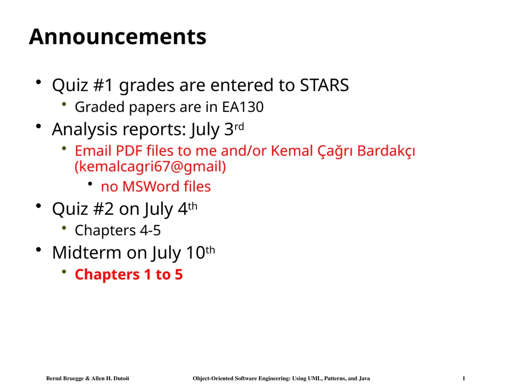
slide1. Announcements Quiz #1 grades are entered to STARS
Graded papers are in EA130
Analysis reports: July 3rd
Email PDF files to me and/or Kemal Çağrı Bardakçı (kemalcagri67@gmail)
no MSWord files
Quiz #2 on July 4th
Chapters 4-5
Midterm on July 10th
Chapters 1 to 5<br>
slide2. Chapter 6 System Design: Decomposing the System<br>
slide3. Design is Difficult There are two ways of constructing a software design (Tony Hoare):
One way is to make it so simple that there are obviously no deficiencies
The other way is to make it so complicated that there are no obvious deficiencies.”

Corollary (Jostein Gaarder):
If our brain would be so simple that we can understand it, we would be too stupid to understand it. Sir Antony Hoare, *1934
Quicksort Jostein Gardner, *1952, writer
- Best known for: „Sophie‘s World“.<br>
slide4. Why is Design so Difficult? Analysis: Focuses on the application domain
Design: Focuses on the solution domain
The solution domain is changing very rapidly
Halftime knowledge in software engineering: About 3-5 years
Cost of hardware rapidly sinking
New technologies emerge
Old technologies become obsolete
Design knowledge is a moving target

Design window: Time in which design decisions have to be made.<br>
slide5. The Scope of System Design Bridge the gap between a problem and an existing system in a manageable way Problem Existing System How?
Use Divide & Conquer:
1) Identify design goals
2) Model the new system design as a set of subsystems
3-8) Address the major design goals.<br>
slide6. System Design: Eight Issues System Design<br>
slide7. How the Analysis Models influence System Design Nonfunctional Requirements
=> Definition of Design Goals
Functional model
=> Subsystem Decomposition
Object model
=> Hardware/Software Mapping, Persistent Data Management
Dynamic model
=> Identification of Concurrency, Global Resource Handling, Software Control
Finally: Hardware/Software Mapping
=> Boundary conditions<br>
slide8. Monolithic
Event-Driven
Conc. Processes 7. Software
Control From Analysis to System Design Object Model Nonfunctional
Requirements<br>
slide9. Example of Design Goals Reliability
Modifiability
Maintainability
Understandability
Adaptability
Reusability
Efficiency
Portability
Traceability of requirements
Fault tolerance
Backward-compatibility
Cost-effectiveness
Robustness
High-performance Good documentation
Well-defined interfaces
User-friendliness
Reuse of components
Rapid development
Minimum number of errors
Readability
Ease of learning
Ease of remembering
Ease of use
Increased productivity
Low-cost
Flexibility<br>
slide10. Stakeholders have different Design Goals Reliability Portability
Good documentation Runtime
Efficiency<br>
slide11. Typical Design Trade-offs Functionality v. Usability
Cost v. Robustness
Efficiency v. Portability
Rapid development v. Functionality
Cost v. Reusability
Backward Compatibility v. Readability<br>
slide12. Subsystem Decomposition Subsystem
Collection of classes, associations, operations, events and constraints that are closely interrelated with each other
The objects and classes from the object model are the “seeds” for the subsystems
In UML subsystems are modeled as packages
Service
A set of named operations provided by the subsystem that share a common purpose
The origin (“seed”) for services are the use cases from the functional model
Services are defined during system design.<br>
slide13. Adds games, styles, and expert rating formulas Stores user profiles (contact info & subscriptions) Stores results of archived tournaments Maintains state during matches Administers user accounts Manages tournaments,promotions, applications Manages advertisement banners & sponsorships Example: Services provided by the ARENA Subsystems Services
are described
by subsystem interfaces<br>
slide14. Subsystem Interfaces vs API Subsystem interface: Set of fully typed UML operations
Specifies the interaction and information flow from and to subsystem boundaries, but not inside the subsystem
Refinement of service, should be well-defined and small
Subsystem interfaces are defined during object design
Application programming interface (API)
The API is the specification of the subsystem interface in a specific programming language
APIs are defined during implementation
The terms subsystem interface and API are often confused with each other
The term API should not be used during system design and object design, but only during implementation.<br>
slide15. Example: Notification subsystem Service provided by Notification Subsystem
LookupChannel()
SubscribeToChannel()
SendNotice()
UnsubscribeFromChannel()
Subsystem Interface of Notification Subsystem
Set of fully typed UML operations
API of Notification Subsystem
Implementation in Java<br>
slide16. Subsystem Interface Object Good design: The subsystem interface object describes all the services of the subsystem interface

Subsystem Interface Object
The set of public operations provided by a subsystem

Subsystem Interface Objects can be realized with the Façade pattern (=> lecture on design patterns).<br>
slide17. Properties of Subsystems: Layers and Partitions A layer is a subsystem that provides a service to another subsystem with the following restrictions:
A layer only depends on services from lower layers
A layer has no knowledge of higher layers
A layer can be divided horizontally into several independent subsystems called partitions
Partitions provide services to other partitions on the same layer
Partitions are also called “weakly coupled” subsystems.<br>
slide18. Relationships between Subsystems Two major types of Layer relationships
Layer A “depends on” Layer B (compile time dependency)
Example: Build dependencies (make, ant, maven)
Layer A “calls” Layer B (runtime dependency)
Example: A web browser calls a web server
Can the client and server layers run on the same machine?
Yes, they are layers, not processor nodes
Mapping of layers to processors is decided during the Software/hardware mapping!
Partition relationship
The subsystems have mutual knowledge about each other
A calls services in B; B calls services in A (Peer-to-Peer)
UML convention:
Runtime dependencies are associations with dashed lines
Compile time dependencies are associations with solid lines.<br>
slide19. F:Subsystem E:Subsystem G:Subsystem D:Subsystem C:Subsystem B:Subsystem A:Subsystem Layer 1 Layer 2 Layer 3 Example of a Subsystem Decomposition Layer
Relationship
„depends on“ Partition
relationship Layer
Relationship
„calls“<br>
slide20. ARENA Subsystem Decomposition<br>
slide21. Example of a Bad Subsystem Decomposition<br>
slide22. Good Design: The System as set of Interface Objects User Interface Tournament Component
Management Session
Management Tournament
Statistics Advertisement User
Management Subsystem Interface Objects<br>
slide23. Virtual Machine A virtual machine is a subsystem connected to higher and lower level virtual machines by "provides services for" associations
Collection of classes
A virtual machine is an abstraction that provides a set of attributes and operations
The terms layer and virtual machine can be used interchangeably
Also sometimes called “level of abstraction”.<br>
slide24. Building Systems as a Set of Virtual Machines A system is a hierarchy of virtual machines, each using language primitives offered by the lower machines. Virtual Machine 1 Virtual Machine 4 . Virtual Machine 3 Virtual Machine 2 Existing System Operating System, Libraries<br>
slide25. Closed Architecture (Opaque Layering) Each virtual machine can only call operations from the layer below VM1 VM2 VM3 VM4 Design goals: Maintainability, flexibility.<br>
slide26. Opaque Layering in ARENA<br>
slide27. Open Architecture (Transparent Layering) Each virtual machine can call operations from any layer below VM4 VM3 VM2 VM1 Design goal: Runtime efficiency<br>
slide28. Layered systems are hierarchical. This is a desirable design, because hierarchy reduces complexity
low coupling
Closed architectures are more portable
Open architectures are more efficient
Layered systems often have a chicken-and egg problem Properties of Layered Systems Symbol Table How do you open the
symbol table when you are
debugging the File
System?<br>
slide29. Coupling and Coherence of Subsystems Goal: Reduce system complexity while allowing change
Coherence measures dependency among classes
High coherence: The classes in the subsystem perform similar tasks and are related to each other via many associations
Low coherence: Lots of miscellaneous and auxiliary classes, almost no associations
Coupling measures dependency among subsystems
High coupling: Changes to one subsystem will have high impact on the other subsystem
Low coupling: A change in one subsystem does not affect any other subsystem. Good Design<br>
slide30. How to achieve high Coherence High coherence can be achieved if most of the interaction is within subsystems, rather than across subsystem boundaries
Questions to ask:
Does one subsystem always call another one for a specific service?
Yes: Consider moving them together into the same subystem.
Which of the subsystems call each other for services?
Can this be avoided by restructuring the subsystems or changing the subsystem interface?
Can the subsystems even be hierarchically ordered (in layers)?<br>
slide31. How to achieve Low Coupling Low coupling can be achieved if a calling class does not need to know anything about the internals of the called class (Principle of information hiding, Parnas)
Questions to ask:
Does the calling class really have to know any attributes of classes in the lower layers?
Is it possible that the calling class calls only operations of the lower level classes?<br>
slide32. Architectural Style vs Architecture Subsystem decomposition: Identification of subsystems, services, and their association to each other (hierarchical, peer-to-peer, etc)

Architectural Style: A pattern for a subsystem decomposition

Software Architecture: Instance of an architectural style.<br>
slide33. Examples of Architectural Styles Client/Server
Peer-To-Peer
Repository
Model/View/Controller
Three-tier, Four-tier Architecture
Service-Oriented Architecture (SOA)
Pipes and Filters<br>
slide34. Client/Server Architectures Often used in the design of database systems
Front-end: User application (client)
Back end: Database access and manipulation (server)
Functions performed by client:
Input from the user (Customized user interface)
Front-end processing of input data
Functions performed by the database server:
Centralized data management
Data integrity and database consistency
Database security<br>
slide35. Client/Server Architectural Style One or many servers provide services to instances of subsystems, called clients Each client calls on the server, which performs some service and returns the result
The clients know the interface of the server The server does not need to know the interface of the client
The response in general is immediate
End users interact only with the client.<br>
slide36. Design Goals for Client/Server Architectures Location-
Transparency Server runs on many operating systems and many networking environments Server might itself be distributed, but provides a single "logical" service to the user Client optimized for interactive display-intensive tasks; Server optimized for CPU-intensive operations Server can handle large # of clients User interface of client supports a variety of end devices (PDA, Handy, laptop, wearable computer) Service Portability High Performance Reliability Scalability Flexibility Server should be able to survive client and communication problems.<br>
slide37. Problems with Client/Server Architectures Client/Server systems do not provide peer-to-peer communication
Peer-to-peer communication is often needed
Example:
Database must process queries from application and should be able to send notifications to the application when data have changed<br>
slide38. Peer-to-Peer Architectural Style Generalization of Client/Server Architectural Style
“Clients can be servers and servers can be clients” Introduction a new abstraction: Peer
“Clients and servers can be both peers”<br>
slide39. Peer-to-Peer Architectural Style Generalization of Client/Server Architectural Style
“Clients can be servers and servers can be clients” Introduction a new abstraction: Peer
“Clients and servers can be both peers”
How do we model this statement? With Inheritance? Proposal 1: “A peer can be either a client or a server” Proposal 2: “A peer can be a client as well as a server”.<br>
slide40. Relationship Client/Server & Peer-to-Peer Problem statement “Clients can be servers and servers can be clients”
Which model is correct? Model 1: “A peer can be either a client or a server” Model 2: “A peer can be a client as well as a server” ✔ ? Model 1 Model 2<br>
slide41. Example: Peer-to-Peer Architectural Style ISO’s OSI Reference Model
ISO = International Standard Organization
OSI = Open System Interconnection
Reference model which defines 7 layers and communication protocols between the layers<br>
slide42. OSI Model Layers and Services The Application layer is the system you are building (unless you build a protocol stack)
The application layer is usually layered itself
The Presentation layer performs data transformation services, such as byte swapping and encryption
The Session layer is responsible for initializing a connection, including authentication !<br>
slide43. OSI Model Layers and their Services The Transport layer is responsible for reliably transmitting messages
Used by Unix programmers who transmit messages over TCP/IP sockets
The Network layer ensures transmission and routing
Services: Transmit and route data within the network
The Datalink layer models frames
Services: Transmit frames without error
The Physical layer represents the hardware interface to the network
Services: sendBit() and receiveBit()<br>
slide44. The Application Layer Provides the Abstractions of the “New System” Application Application<br>
slide45. An Object-Oriented View of the OSI Model The OSI Model is a closed software architecture (i.e., it uses opaque layering)
Each layer can be modeled as a UML package containing a set of classes available for the layer above<br>
slide47. Providing Consistent Views Problem: In systems with high coupling, changes to the user interface (boundary objects) often force changes to the entity objects (data)
The user interface cannot be re-implemented without changing the representation of the entity objects
The entity objects cannot be reorganized without changing the user interface
Solution: Decoupling! The model-view-controller architectural style decouples data access (entity objects) and data presentation (boundary objects)
The Data Presentation subsystem is called the View
The Data Access subsystem is called the Model
The Controller subsystem mediates between View (data presentation) and Model (data access)
Often called MVC.<br>
slide48. Model-View-Controller Architectural Style Subsystems are classified into 3 different types
Model subsystem: Responsible for application domain knowledge View subsystem: Responsible for displaying application domain objects to the user Controller subsystem: Responsible for sequence of interactions with the user and notifying views of changes in the model Class Diagram Better understanding with a Collaboration Diagram<br>
slide49. UML Collaboration Diagram A Collaboration Diagram is an instance diagram that visualizes the interactions between objects as a flow of messages. Messages can be events or calls to operations
Communication diagrams describe the static structure as well as the dynamic behavior of a system:
Hybrid of class, statechart and sequence diagrams
The static structure is obtained from the UML class diagram
Communication diagrams reuse the layout of classes and associations in the class diagram
The dynamic behavior is obtained from the dynamic model (UML sequence diagrams and UML statechart diagrams)
Messages between objects are labeled with a chronological number and placed near the link the message is sent over
Reading a communication diagram involves starting at message 1.0, and following the messages from object to object.<br>
slide50. Example: Modeling the Sequence of Events in MVC 1.0 Subscribe UML Collaboration Diagram UML Class Diagram 3.0Subscribe 2.0Subscribe<br>
slide51. 3-Layer-Architectural Style 3-Tier Architecture Definition: 3-Layer Architectural Style
An architectural style, where an application consists of 3 hierarchically ordered subsystems
A user interface, middleware and a database system
The middleware subsystem services data requests between the user interface and the database subsystem
Definition: 3-Tier Architecture
A software architecture with 3 layers
Note: Layer is a type (e.g. class, subsystem) and Tier is an instance (e.g. object, hardware node)
Layer and Tier are often used interchangeably.<br>
slide52. Virtual Machines in 3-Layer Architectural Style A 3-Layer Architectural Style is a hierarchy of 3 virtual machines usually called presentation, application and data layer Data Layer Presentation Layer
(Client Layer) Application Layer
(Middleware,
Business Logic) Existing System Operating System, Libraries<br>
slide53. Example of a 3-Layer Architectural Style Three-Layer architectural style are often used for the development of Websites:
1. The Web Browser implements the user interface
2. The Web Server serves requests from the web browser
3. The Database manages and provides access to the persistent data.<br>
slide54. Example of a 4-Layer Architectural Style 4-Layer-architectural styles (4-Tier Architectures) are usually used for the development of electronic commerce sites. The layers are
The Web Browser, providing the user interface
A Web Server, serving static HTML requests
An Application Server, providing session management (for example the contents of an electronic shopping cart) and processing of dynamic HTML requests
A back end Database, that manages and provides access to the persistent data
In current 4-tier architectures, this is usually a relational Database management system (RDBMS).<br>
slide55. Summary System Design
An activity that reduces the gap between the problem and an existing (virtual) machine
Design Goals Definition
Describes the important system qualities
Defines the values against which options are evaluated
Subsystem Decomposition
Decomposes the overall system into manageable parts by using the principles of cohesion and coherence
Architectural Style
A pattern of a typical subsystem decomposition
Software architecture
An instance of an architectural style
Client Server, Peer-to-Peer, Model-View-Controller.<br>
slide56. Announcements Quiz #1 grades are entered to STARS
Graded papers are in EA130
Analysis reports: July 3rd
Email PDF files to me and/or Kemal Çağrı Bardakçı (kemalcagri67@gmail)
no MSWord files
Quiz #2 on July 4th
Chapters 4-5
Midterm on July 10th
Chapters 1 to 5
No class on July 3rd<br>