
Architectural Analysis These slides are derived

Description: Architectural Analysis These slides are derived from IBMRational slides from courses on UML and object-oriented design and analysis. Copyright to the original slides resides with IBMRational. They are used here, in this course, under
Related Topics
Download Presentation
"Architectural Analysis These slides are derived" is the property of its rightful owner. Permission is granted to download and print the materials on this website for personal, non-commercial use only, and to display it on your personal computer provided you do not modify the materials and that you retain all copyright notices contained in the materials. By downloading content from our website, you accept the terms of this agreement.
Presentation Transcript
slide1. Architectural Analysis These slides are derived from IBM/Rational slides from courses on UML and object-oriented design and analysis.
Copyright to the original slides resides with IBM/Rational. They are used here, in this course, under password protection limited to students enrolled in the course, with permission of the owners, but are not to be published or further distributed.<br>
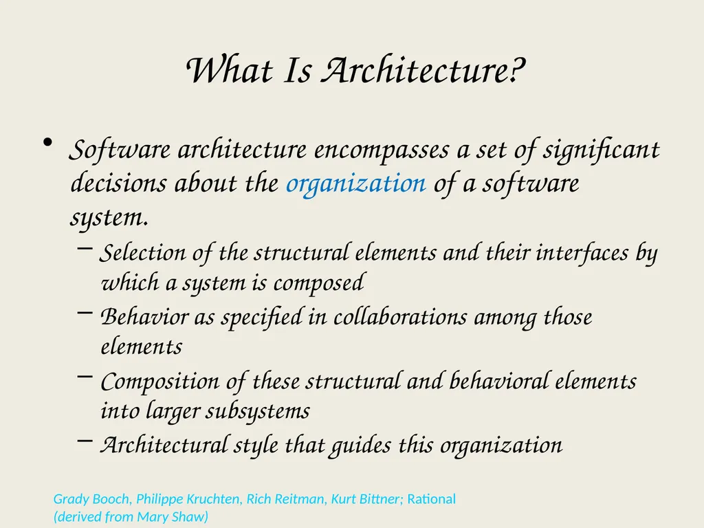
slide2. What Is Architecture? Software architecture encompasses a set of significant decisions about the organization of a software system.
Selection of the structural elements and their interfaces by which a system is composed
Behavior as specified in collaborations among those elements
Composition of these structural and behavioral elements into larger subsystems
Architectural style that guides this organization Grady Booch, Philippe Kruchten, Rich Reitman, Kurt Bittner; Rational
(derived from Mary Shaw)<br>
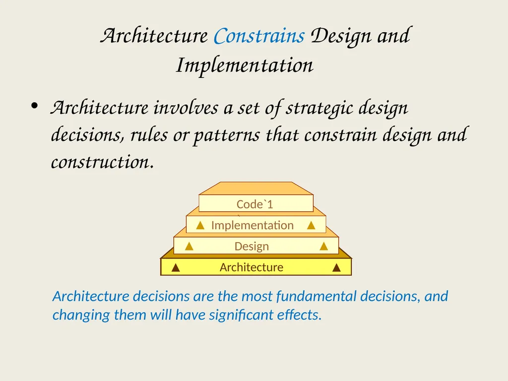
slide3. Architecture Constrains Design and Implementation Architecture involves a set of strategic design decisions, rules or patterns that constrain design and construction. Architecture decisions are the most fundamental decisions, and changing them will have significant effects. Architecture Design Implementation Code`1`<br>
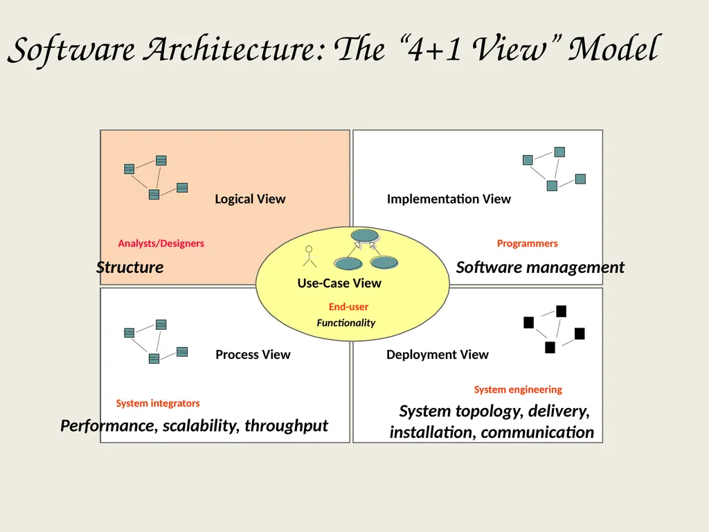
slide4. Software Architecture: The “4+1 View” Model Process View Deployment View Logical View Use-Case View Implementation View End-user Functionality Programmers Software management Performance, scalability, throughput System integrators System topology, delivery,
installation, communication System engineering Analysts/Designers Structure<br>
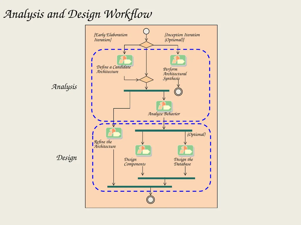
slide5. Analysis and Design Workflow Analysis Design [Early Elaboration Iteration] [Inception Iteration (Optional)] Define a Candidate
Architecture Perform
Architectural
Synthesis Analyze Behavior Refine the
Architecture Design
Components Design the
Database (Optional)<br>
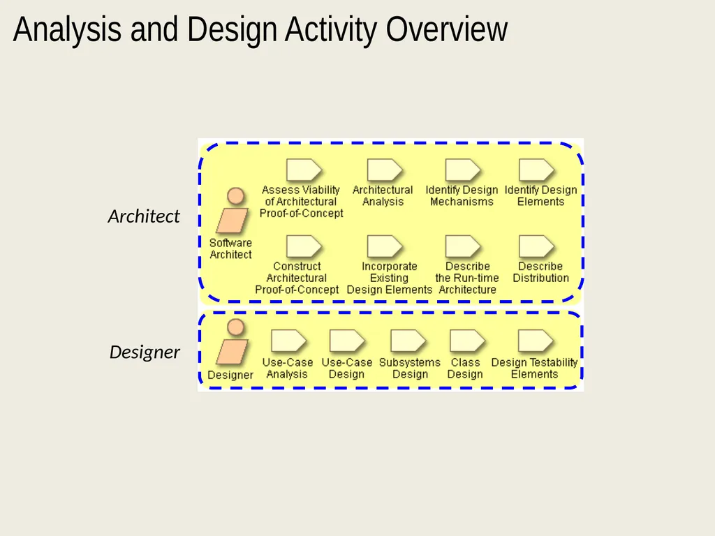
slide6. Analysis and Design Activity Overview Architect Designer<br>
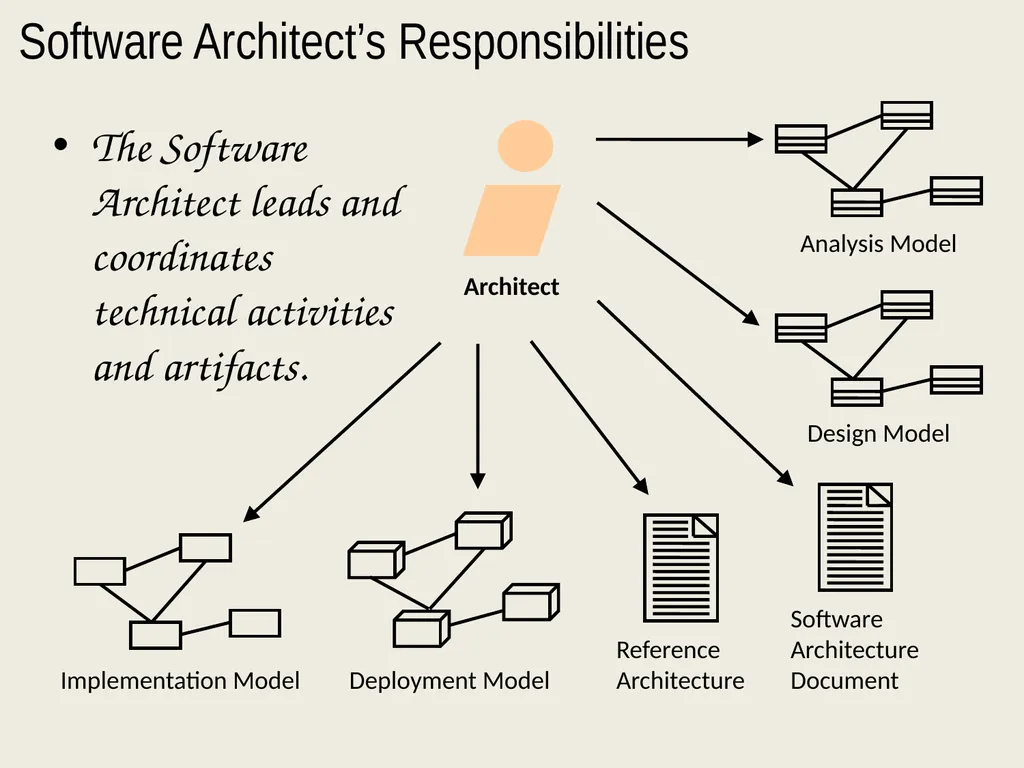
slide7. Software Architect’s Responsibilities Architect The Software Architect leads and coordinates technical activities and artifacts. Deployment Model Implementation Model<br>
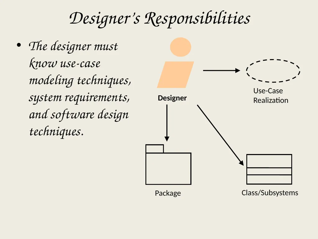
slide8. Designer’s Responsibilities Designer The designer must know use-case modeling techniques, system requirements, and software design techniques.<br>
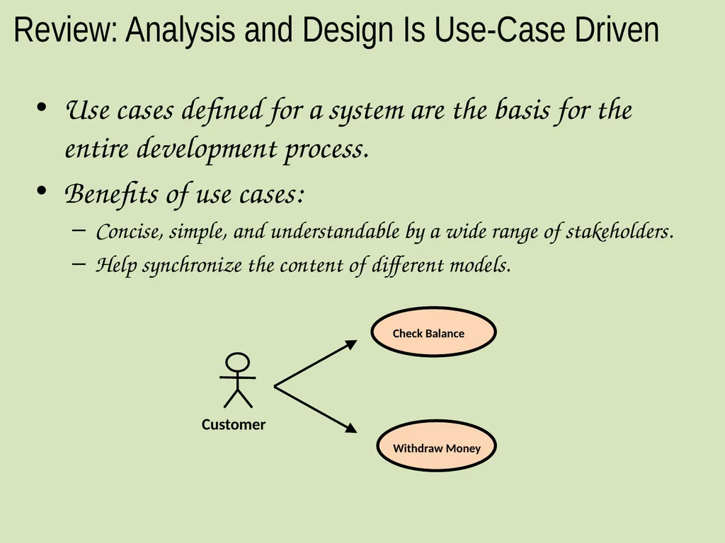
slide9. Review: Analysis and Design Is Use-Case Driven Use cases defined for a system are the basis for the entire development process.
Benefits of use cases:
Concise, simple, and understandable by a wide range of stakeholders.
Help synchronize the content of different models. Withdraw Money Check Balance<br>
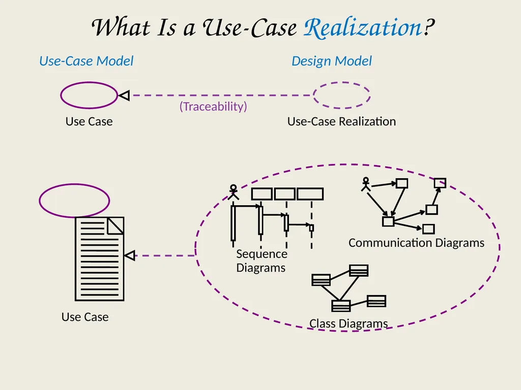
slide10. What Is a Use-Case Realization? Use Case Communication Diagrams Use-Case Model Design Model Use Case Use-Case Realization Sequence Diagrams (Traceability)<br>
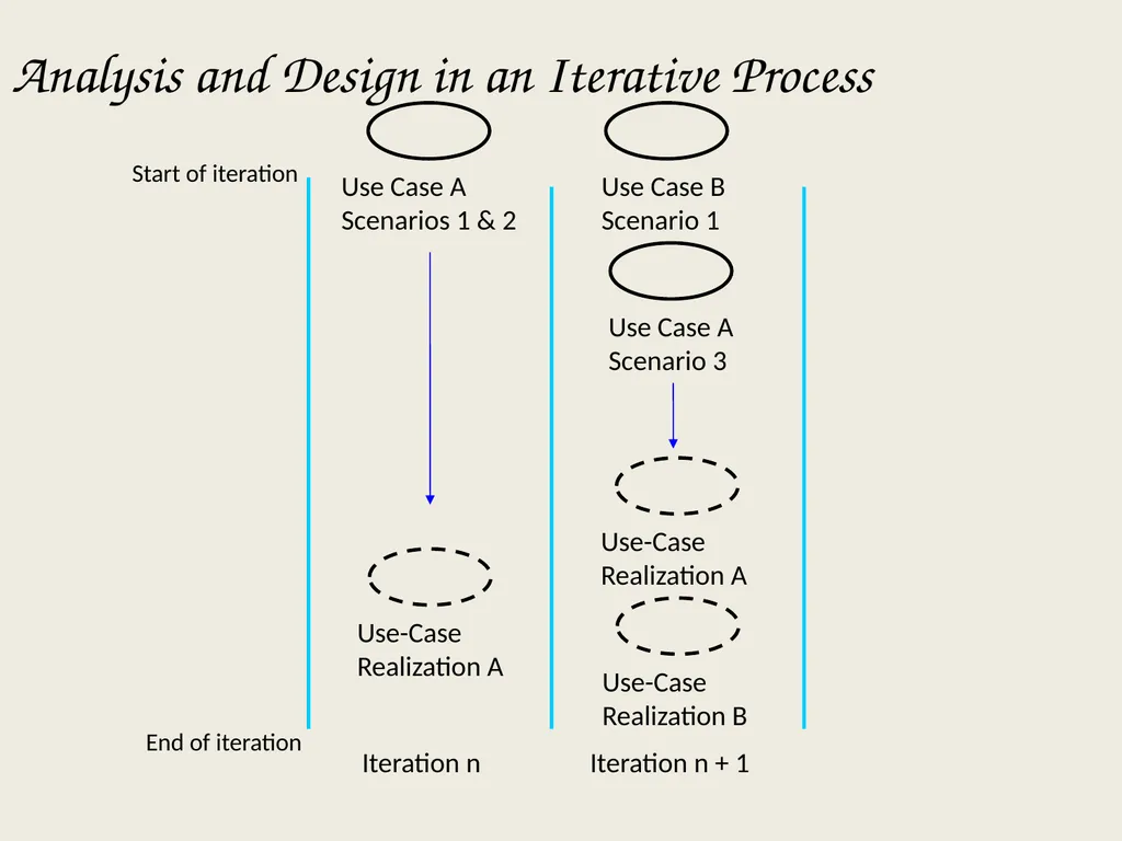
slide11. Analysis and Design in an Iterative Process Iteration n Iteration n + 1 Start of iteration End of iteration<br>
slide12. Review What is the purpose of the Analysis and Design Discipline?
What are the input and output artifacts?
Name and briefly describe the 4+1 Views of Architecture.
What is the difference between Analysis and Design?
What is architecture?<br>
slide13. ARCHITECTURAL ANALYSIS<br>
slide14. KEY CONCEPTS<br>
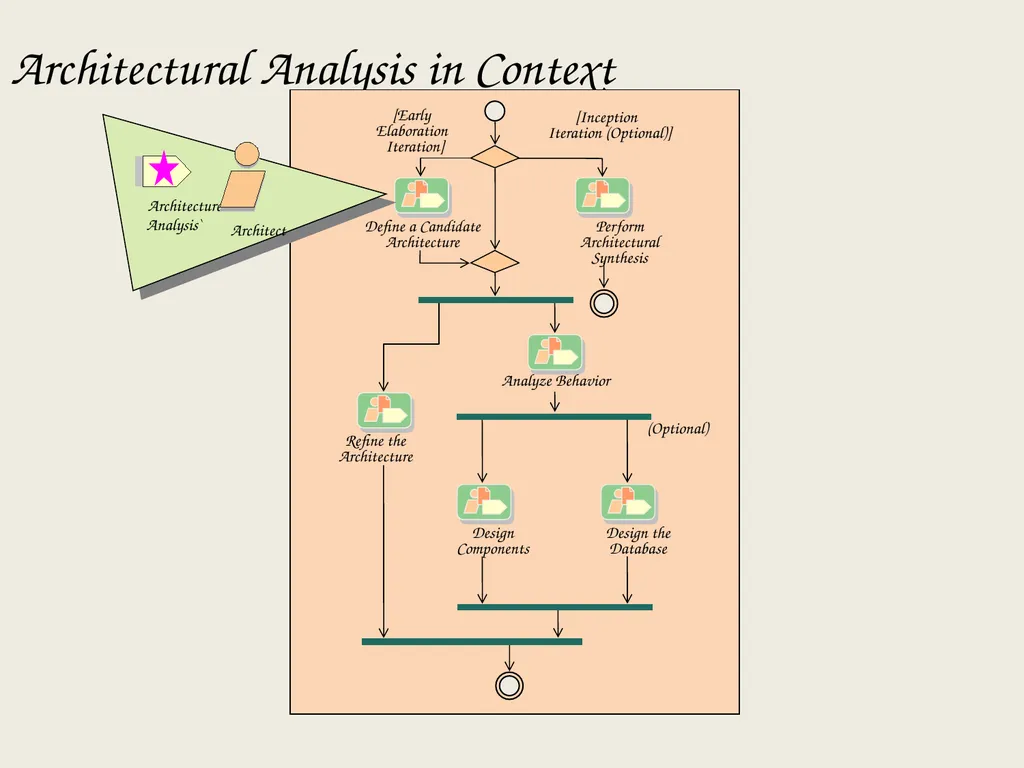
slide15. Architectural Analysis in Context [Early
Elaboration
Iteration] [Inception
Iteration (Optional)] Define a Candidate
Architecture Perform
Architectural
Synthesis Analyze Behavior Refine the
Architecture Design
Components Design the
Database (Optional) Architecture Analysis`<br>
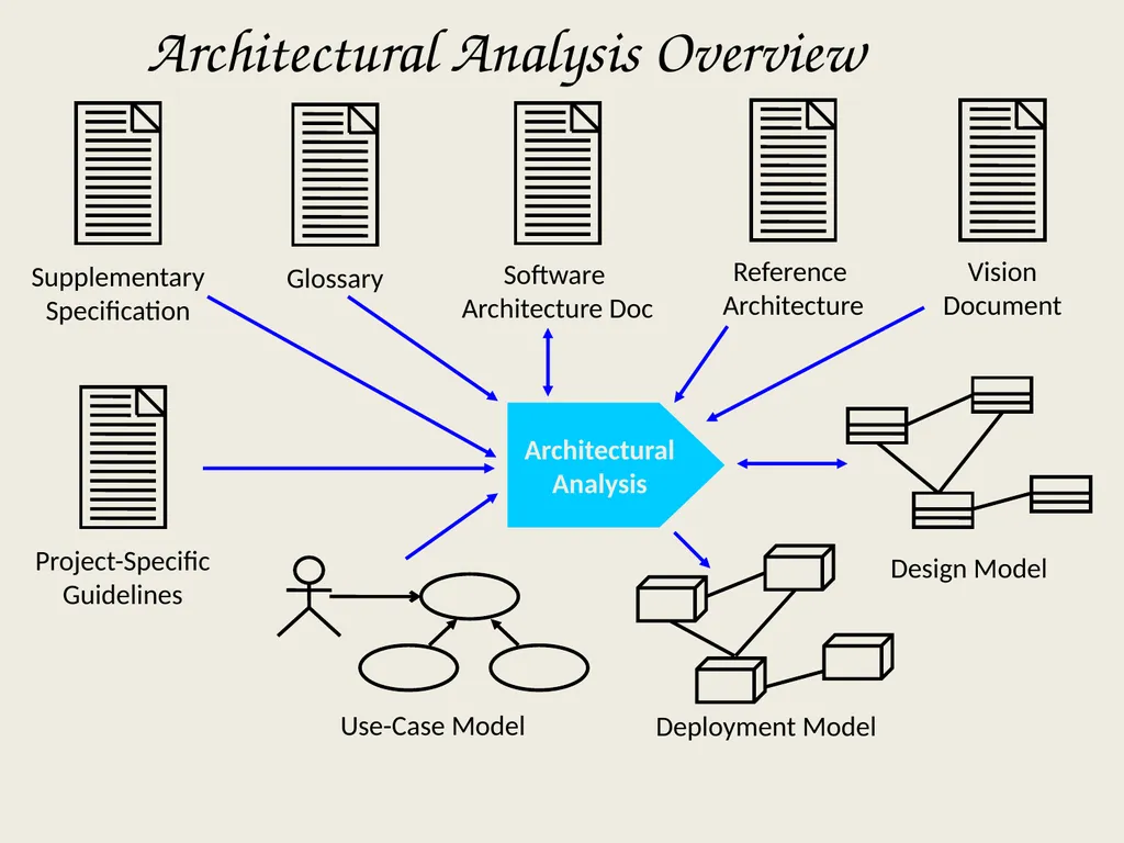
slide16. Architectural Analysis Overview Architectural
Analysis Deployment Model<br>
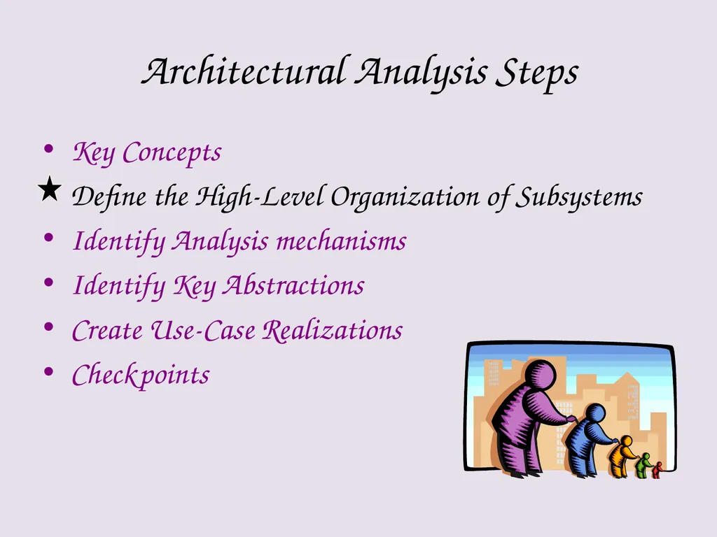
slide17. Architectural Analysis Steps Key Concepts
Define the High-Level Organization of Subsystems
Identify Analysis mechanisms
Identify Key Abstractions
Create Use-Case Realizations
Checkpoints<br>
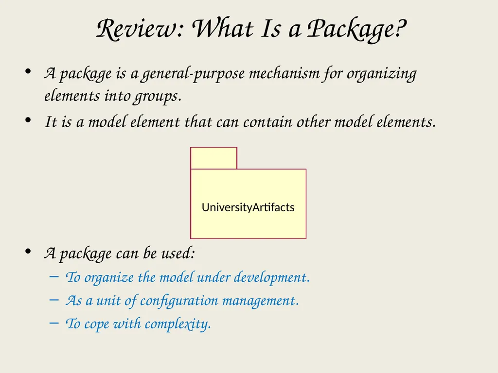
slide18. A package is a general-purpose mechanism for organizing elements into groups.
It is a model element that can contain other model elements.
A package can be used:
To organize the model under development.
As a unit of configuration management.
To cope with complexity. Review: What Is a Package? UniversityArtifacts<br>
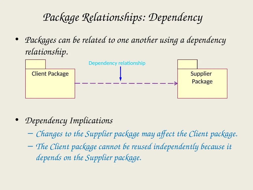
slide19. Packages can be related to one another using a dependency relationship.
Dependency Implications
Changes to the Supplier package may affect the Client package.
The Client package cannot be reused independently because it depends on the Supplier package. Package Relationships: Dependency Dependency relationship<br>
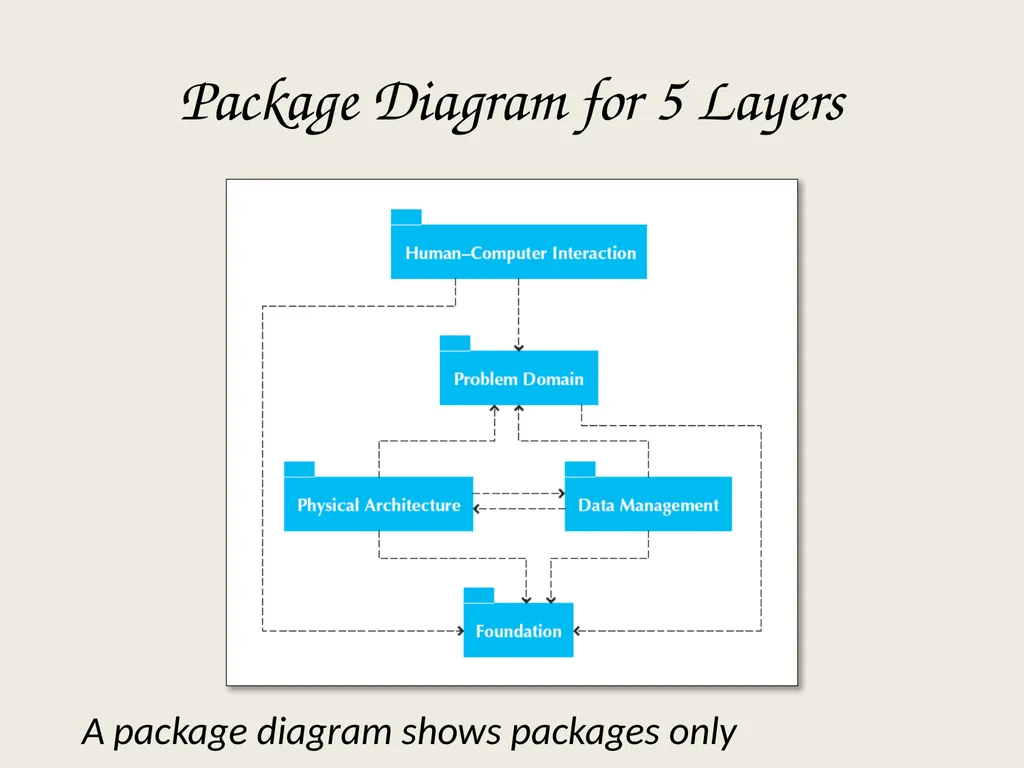
slide20. Package Diagram for 5 Layers A package diagram shows packages only<br>
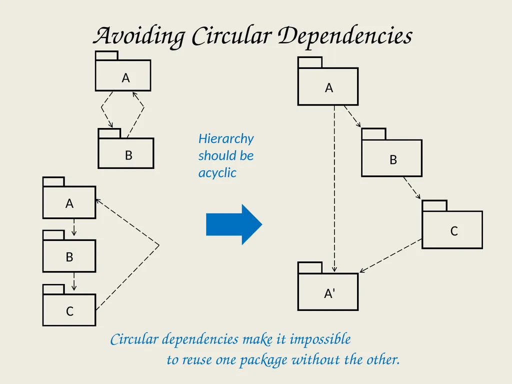
slide21. C A B Hierarchy should be acyclic A B C A' Circular dependencies make it impossible to reuse one package without the other. Avoiding Circular Dependencies A B<br>
slide22. Architectural Analysis Steps Key Concepts
Define the High-Level Organization of Subsystems
Identify Analysis mechanisms
Identify Key Abstractions
Create Use-Case Realizations
Checkpoints<br>
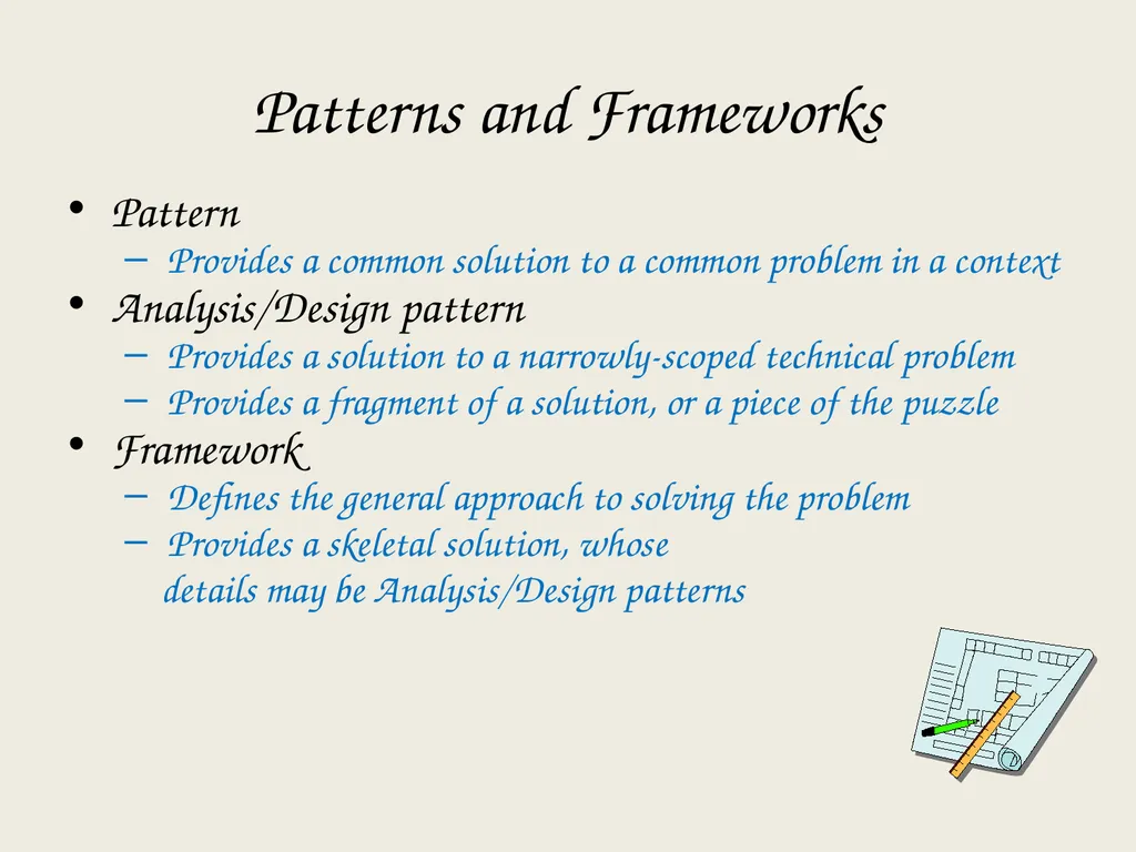
slide23. Patterns and Frameworks Pattern
Provides a common solution to a common problem in a context
Analysis/Design pattern
Provides a solution to a narrowly-scoped technical problem
Provides a fragment of a solution, or a piece of the puzzle
Framework
Defines the general approach to solving the problem
Provides a skeletal solution, whose
details may be Analysis/Design patterns<br>
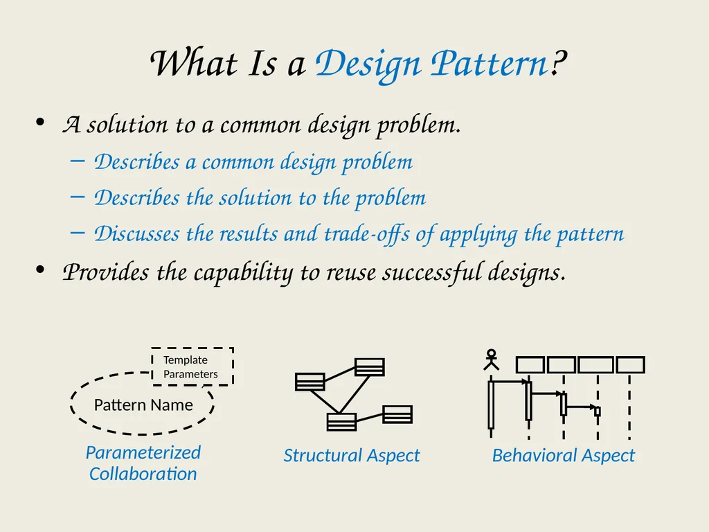
slide24. Structural Aspect Behavioral Aspect What Is a Design Pattern? A solution to a common design problem.
Describes a common design problem
Describes the solution to the problem
Discusses the results and trade-offs of applying the pattern
Provides the capability to reuse successful designs. Parameterized Collaboration<br>
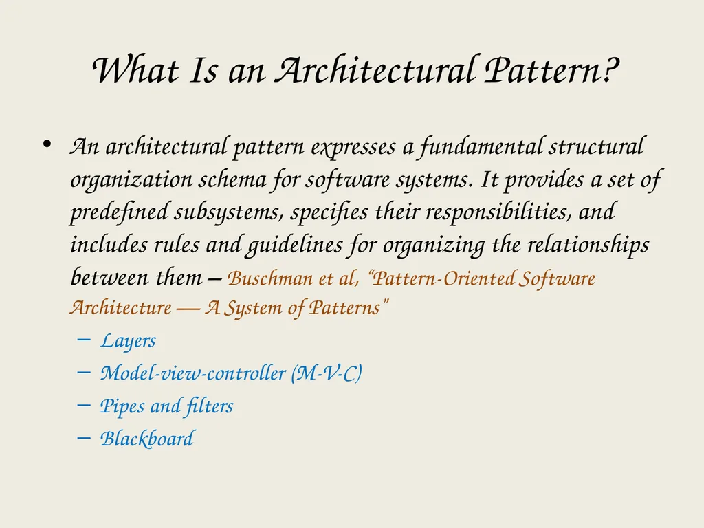
slide25. What Is an Architectural Pattern? An architectural pattern expresses a fundamental structural organization schema for software systems. It provides a set of predefined subsystems, specifies their responsibilities, and includes rules and guidelines for organizing the relationships between them – Buschman et al, “Pattern-Oriented Software Architecture — A System of Patterns”
Layers
Model-view-controller (M-V-C)
Pipes and filters
Blackboard<br>
slide26. Evolving the Analysis Models into Design Models<br>
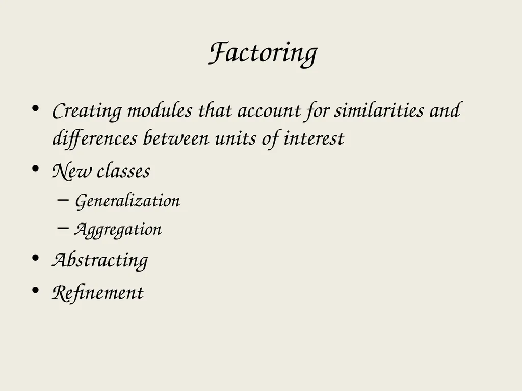
slide27. Factoring Creating modules that account for similarities and differences between units of interest
New classes
Generalization
Aggregation
Abstracting
Refinement<br>
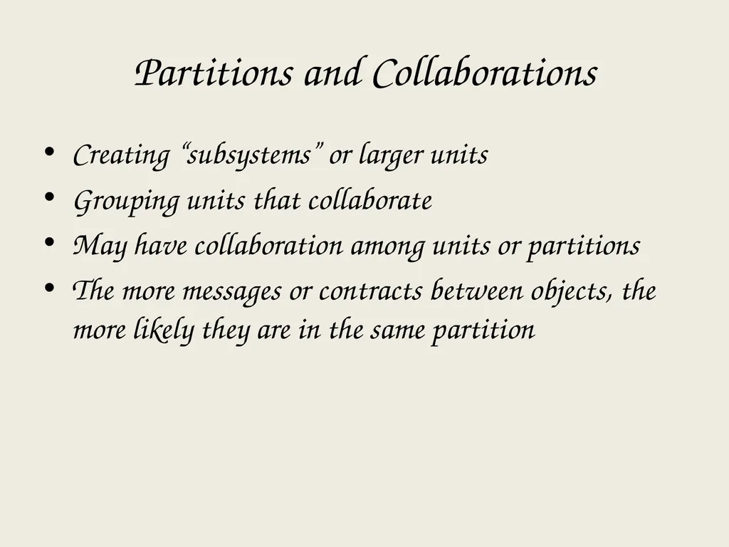
slide28. Partitions and Collaborations Creating “subsystems” or larger units
Grouping units that collaborate
May have collaboration among units or partitions
The more messages or contracts between objects, the more likely they are in the same partition<br>
slide29. Layers Consider system environment information to help evolve the analysis model
Model-view-controller (MVC) architecture
Separating application logic from user interface logic<br>
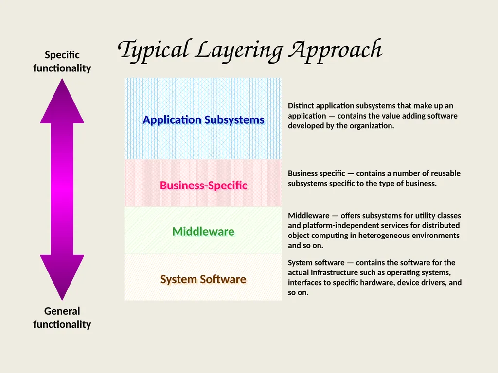
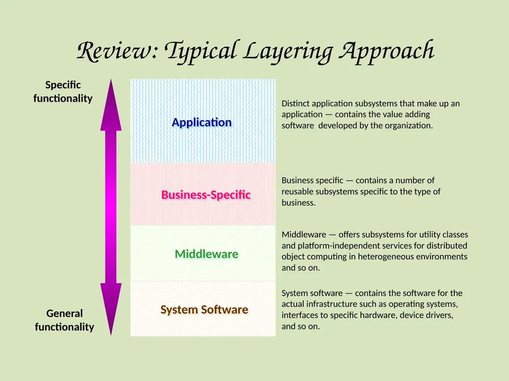
slide30. Typical Layering Approach General functionality Specific functionality Distinct application subsystems that make up an application — contains the value adding software developed by the organization. Business specific — contains a number of reusable subsystems specific to the type of business. Middleware — offers subsystems for utility classes and platform-independent services for distributed object computing in heterogeneous environments and so on. System software — contains the software for the actual infrastructure such as operating systems, interfaces to specific hardware, device drivers, and so on. Application Subsystems Business-Specific Middleware System Software<br>
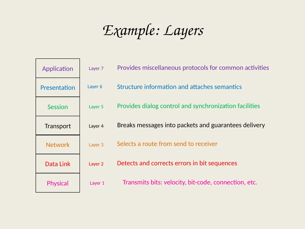
slide31. Example: Layers Application Layer 7 Layer 6 Layer 5 Layer 4 Layer 3 Layer 2 Layer 1 Provides miscellaneous protocols for common activities Structure information and attaches semantics Provides dialog control and synchronization facilities Breaks messages into packets and guarantees delivery Selects a route from send to receiver Detects and corrects errors in bit sequences Transmits bits: velocity, bit-code, connection, etc.<br>
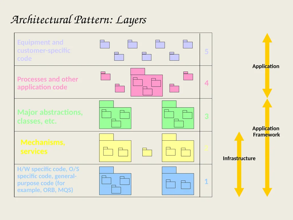
slide32. Architectural Pattern: Layers Equipment and
customer-specific
code Processes and other application code Major abstractions, classes, etc. Mechanisms,
services H/W specific code, O/S specific code, general-purpose code (for example, ORB, MQS) 5 4 3 2 1 Application Application
Framework Infrastructure<br>
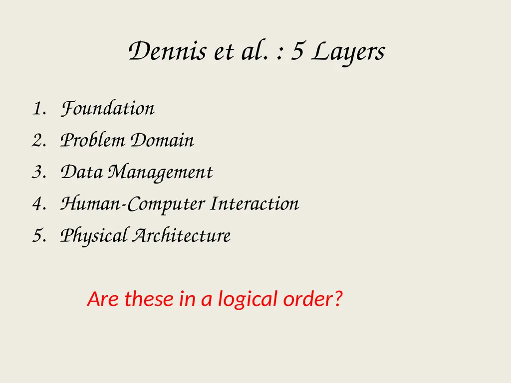
slide33. Dennis et al. : 5 Layers Foundation
Problem Domain
Data Management
Human-Computer Interaction
Physical Architecture Are these in a logical order?<br>
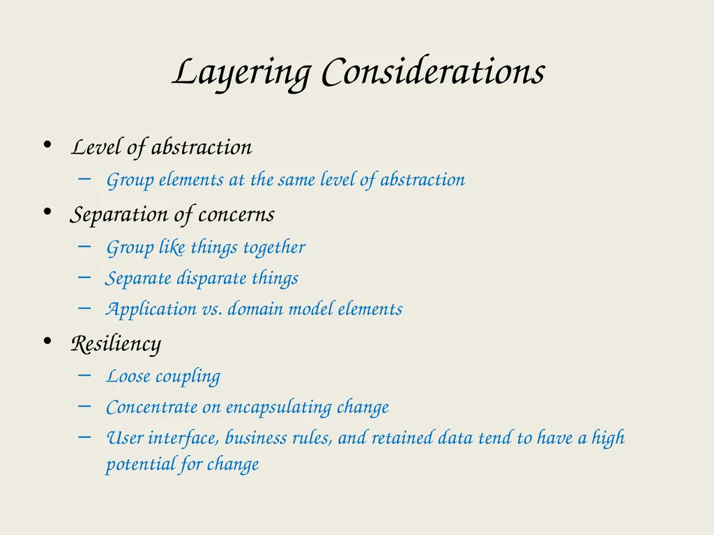
slide34. Layering Considerations Level of abstraction
Group elements at the same level of abstraction
Separation of concerns
Group like things together
Separate disparate things
Application vs. domain model elements
Resiliency
Loose coupling
Concentrate on encapsulating change
User interface, business rules, and retained data tend to have a high potential for change<br>
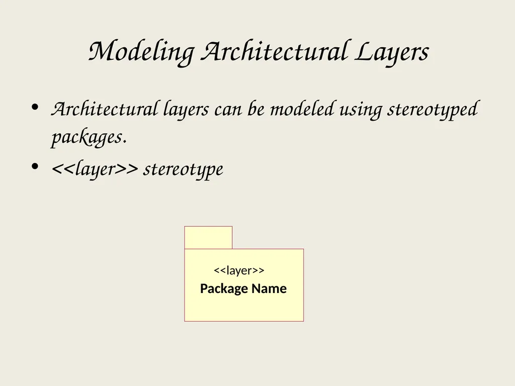
slide35. Modeling Architectural Layers Architectural layers can be modeled using stereotyped packages.
<<layer>> stereotype Package Name <<layer>><br>
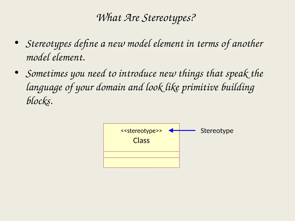
slide36. Class <<stereotype>> What Are Stereotypes? Stereotypes define a new model element in terms of another model element.
Sometimes you need to introduce new things that speak the language of your domain and look like primitive building blocks. Stereotype<br>
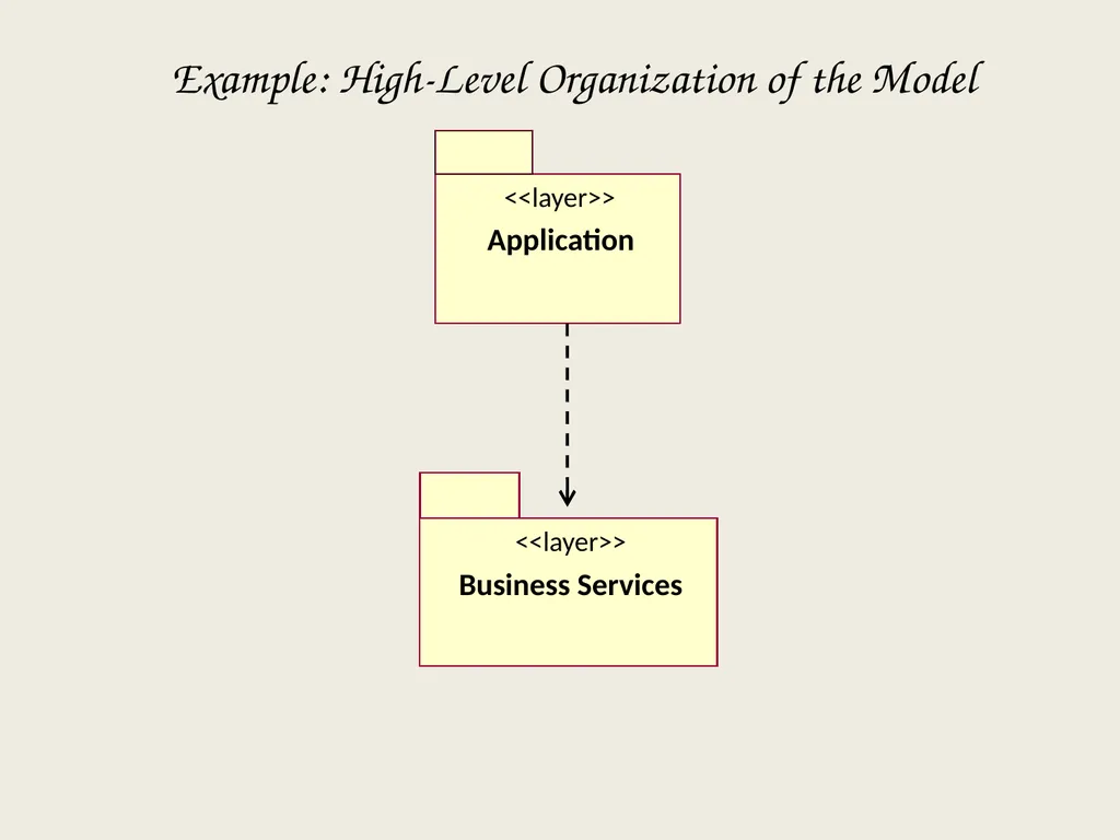
slide37. Example: High-Level Organization of the Model Application <<layer>> Business Services <<layer>><br>
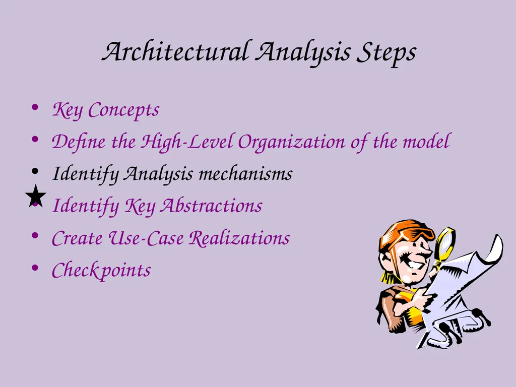
slide38. Architectural Analysis Steps Key Concepts
Define the High-Level Organization of the model
Identify Analysis mechanisms
Identify Key Abstractions
Create Use-Case Realizations
Checkpoints<br>
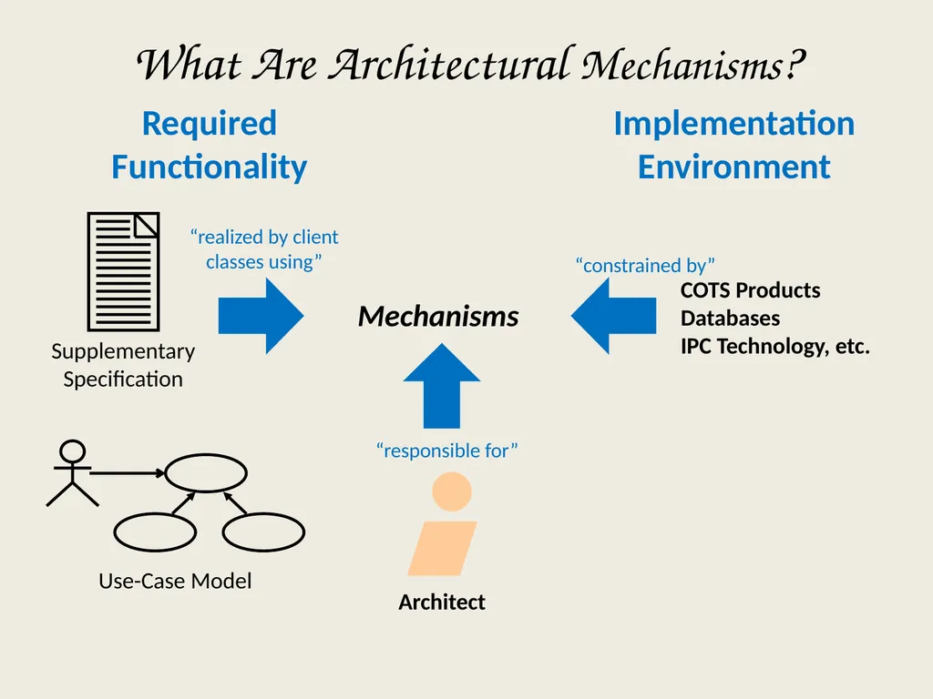
slide39. Mechanisms COTS Products Databases IPC Technology, etc. “realized by client classes using” “responsible for” “constrained by” Required Functionality Implementation Environment What Are Architectural Mechanisms?<br>
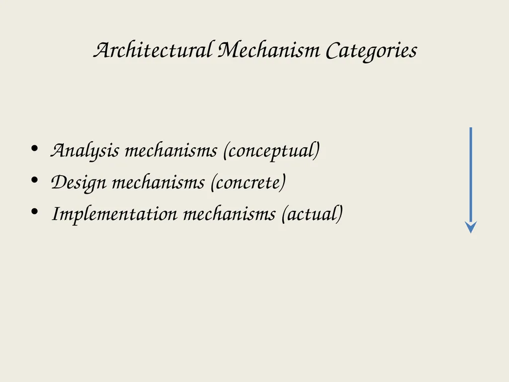
slide40. Architectural Mechanism Categories Analysis mechanisms (conceptual)
Design mechanisms (concrete)
Implementation mechanisms (actual)<br>
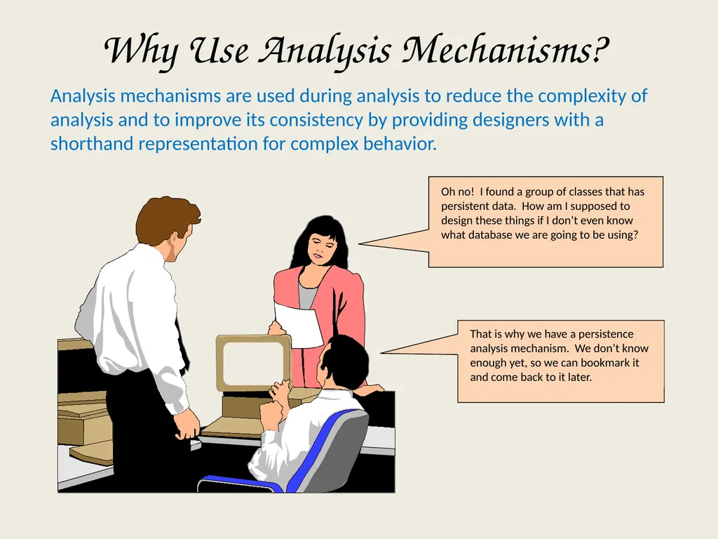
slide41. Why Use Analysis Mechanisms? Oh no! I found a group of classes that has persistent data. How am I supposed to design these things if I don’t even know what database we are going to be using? That is why we have a persistence analysis mechanism. We don’t know enough yet, so we can bookmark it and come back to it later. Analysis mechanisms are used during analysis to reduce the complexity of analysis and to improve its consistency by providing designers with a shorthand representation for complex behavior.<br>
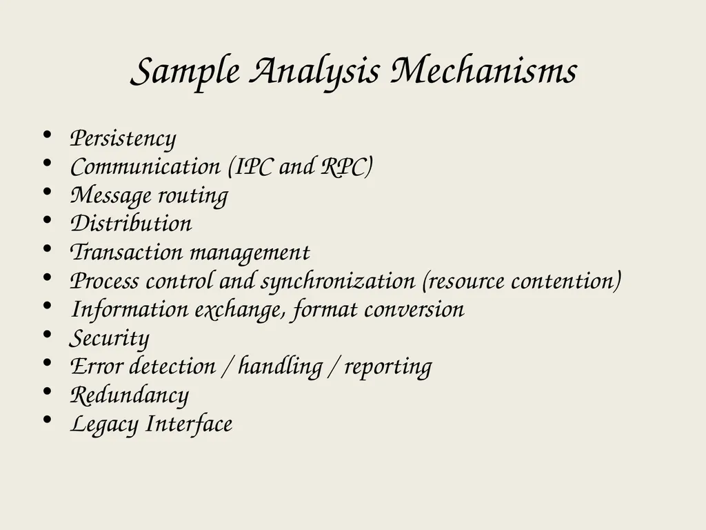
slide42. Sample Analysis Mechanisms Persistency
Communication (IPC and RPC)
Message routing
Distribution
Transaction management
Process control and synchronization (resource contention)
Information exchange, format conversion
Security
Error detection / handling / reporting
Redundancy
Legacy Interface<br>
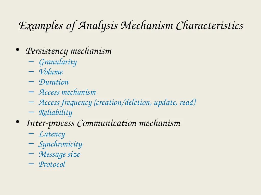
slide43. Examples of Analysis Mechanism Characteristics Persistency mechanism
Granularity
Volume
Duration
Access mechanism
Access frequency (creation/deletion, update, read)
Reliability
Inter-process Communication mechanism
Latency
Synchronicity
Message size
Protocol<br>
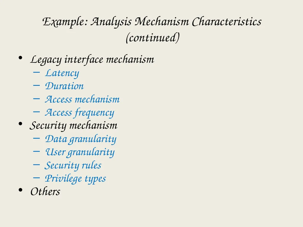
slide44. Example: Analysis Mechanism Characteristics (continued) Legacy interface mechanism
Latency
Duration
Access mechanism
Access frequency
Security mechanism
Data granularity
User granularity
Security rules
Privilege types
Others<br>
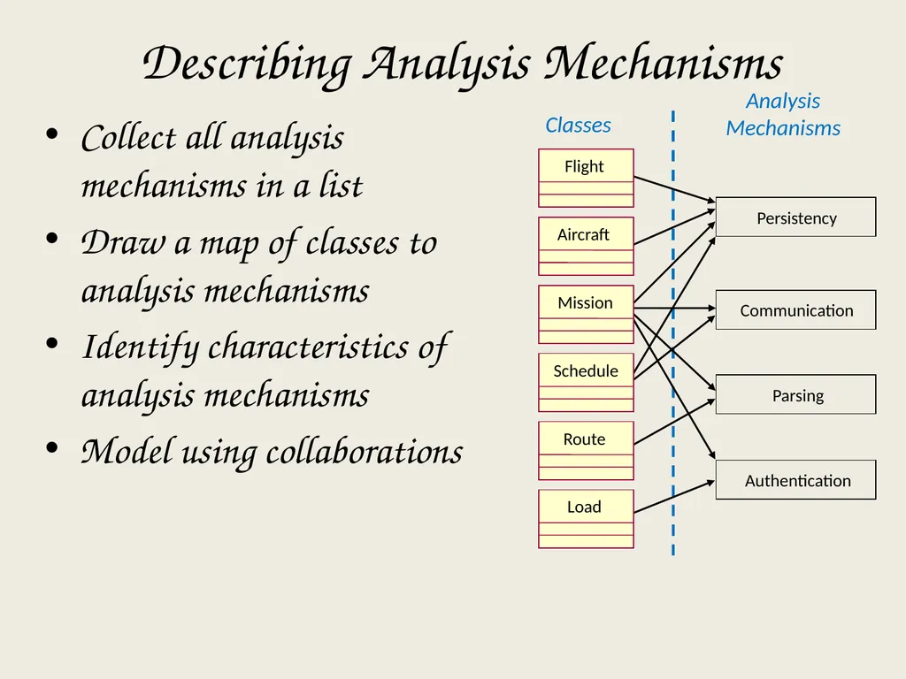
slide45. Collect all analysis mechanisms in a list
Draw a map of classes to analysis mechanisms
Identify characteristics of analysis mechanisms
Model using collaborations Describing Analysis Mechanisms Classes Parsing Authentication Communication Persistency Analysis Mechanisms Flight Aircraft Mission Schedule Route Load<br>
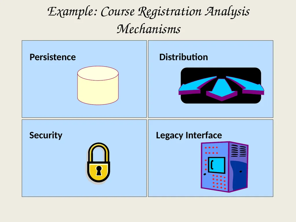
slide46. Example: Course Registration Analysis Mechanisms Security Legacy Interface Persistence Distribution<br>
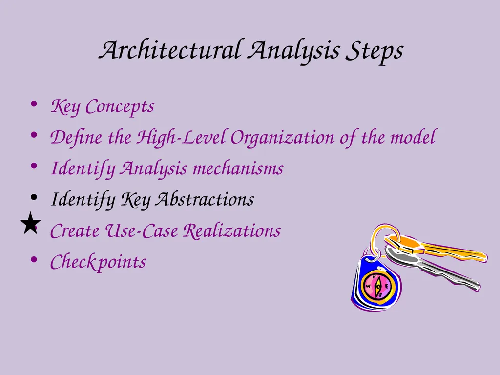
slide47. Architectural Analysis Steps Key Concepts
Define the High-Level Organization of the model
Identify Analysis mechanisms
Identify Key Abstractions
Create Use-Case Realizations
Checkpoints<br>
slide48. What Are Key Abstractions? A key abstraction is a concept, normally uncovered in Requirements, that the system must be able to handle
Sources for key abstractions Domain knowledge
Requirements
Glossary
Domain Model, or the Business Model (if one exists)<br>
slide49. Defining Key Abstractions Define analysis classes
Model analysis classes and relationships on class diagrams
Include a brief description of an analysis class
Map analysis classes to necessary analysis mechanisms<br>
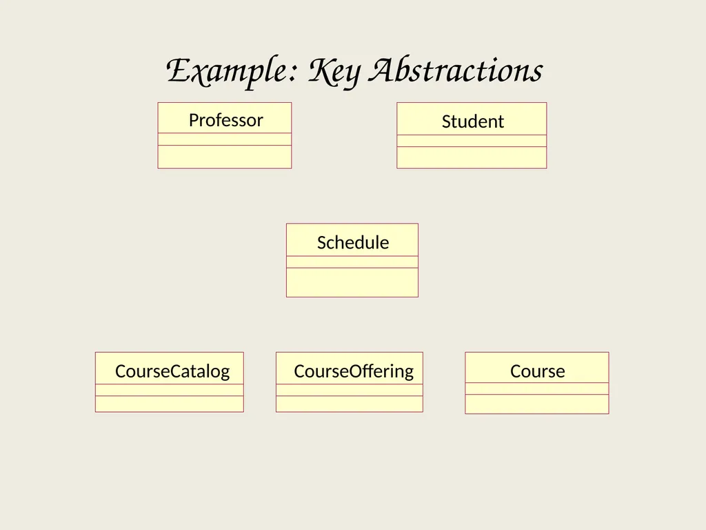
slide50. Example: Key Abstractions<br>
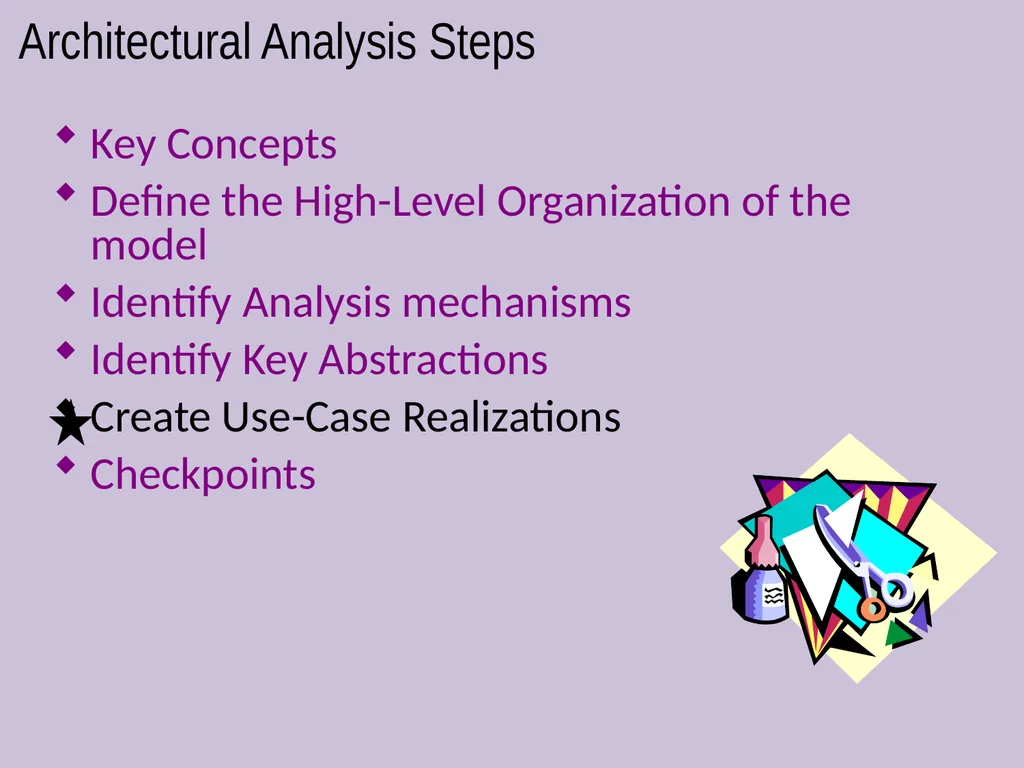
slide51. Architectural Analysis Steps Key Concepts
Define the High-Level Organization of the model
Identify Analysis mechanisms
Identify Key Abstractions
Create Use-Case Realizations
Checkpoints<br>
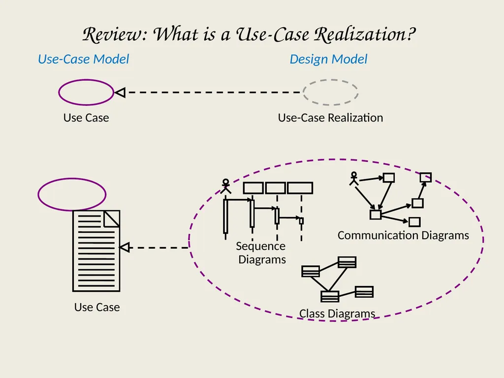
slide52. Review: What is a Use-Case Realization? Use Case Communication Diagrams Use-Case Model Design Model Use Case Use-Case Realization Sequence Diagrams<br>
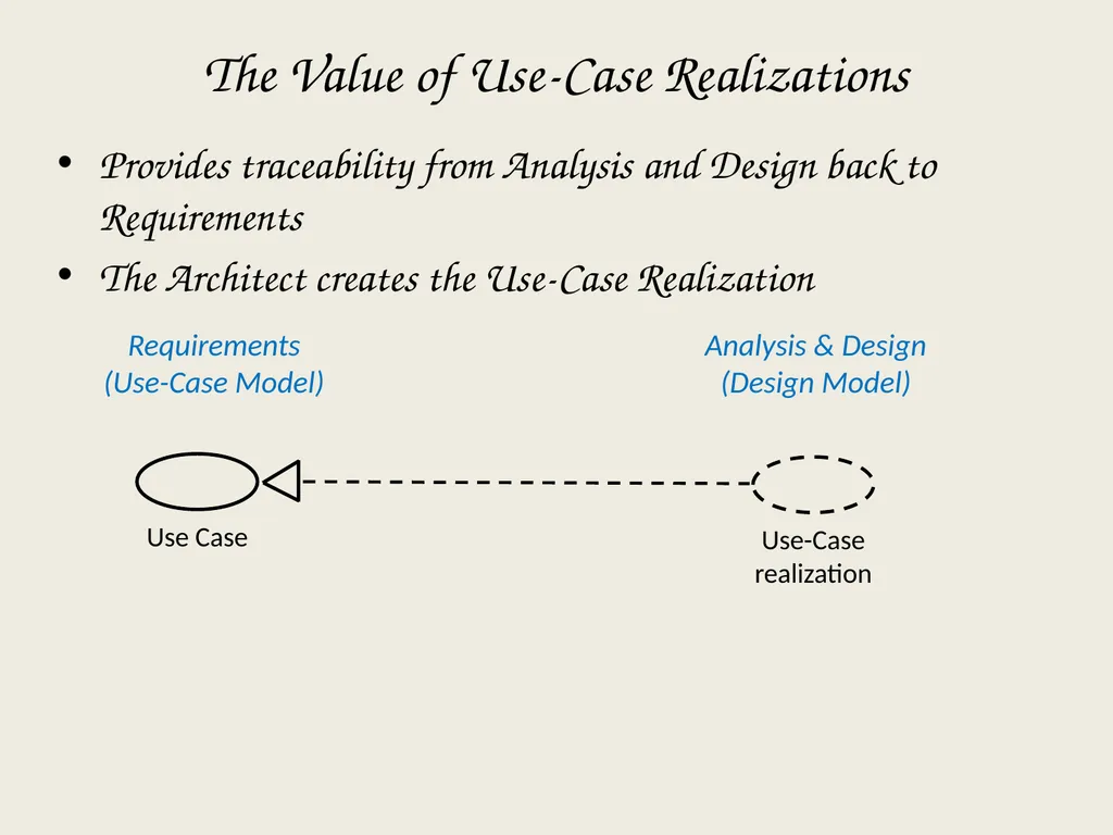
slide53. The Value of Use-Case Realizations Provides traceability from Analysis and Design back to Requirements
The Architect creates the Use-Case Realization Analysis & Design
(Design Model) Requirements
(Use-Case Model) Use-Case realization<br>
slide54. Architectural Analysis Steps Key Concepts
Define the High-Level Organization of the model
Identify Analysis mechanisms
Identify Key Abstractions
Create Use-Case Realizations
Checkpoints<br>
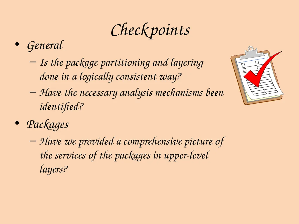
slide55. Checkpoints General
Is the package partitioning and layering done in a logically consistent way?
Have the necessary analysis mechanisms been identified?
Packages
Have we provided a comprehensive picture of the services of the packages in upper-level layers?<br>
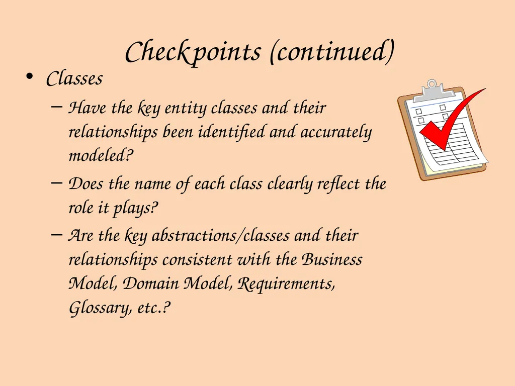
slide56. Checkpoints (continued) Classes
Have the key entity classes and their relationships been identified and accurately modeled?
Does the name of each class clearly reflect the role it plays?
Are the key abstractions/classes and their relationships consistent with the Business Model, Domain Model, Requirements, Glossary, etc.?<br>
slide57. Review: Architectural Analysis What is the purpose of Architectural Analysis?
What is a package?
What is a layered architecture? Give examples of typical layers.
What are analysis mechanisms? Give examples.
What key abstractions are identified during Architectural Analysis? Why are they identified here?<br>
slide58. Building Package Diagrams Set the context
Cluster classes together based on shared relationships
Model clustered classes as a package
Identify dependency relationships among packages
Place dependency relationships between packages<br>
slide59. Design Strategies<br>
slide60. Custom Development Allows for meeting highly specialized requirements
Allows flexibility and creativity in solving problems
Easier to change components
Builds personnel skills
May tax firm’s resources
May add significant risk<br>
slide61. Packaged Software Software already written
May be more efficient
May be more thoroughly tested and proven
May range from components to tools to whole enterprise systems
Must accept functionality provided
May require change in how the firm does business
May require significant “customization” or “workarounds”<br>
slide62. System Integration The process of combining packages, legacy systems, and new software
Key challenge is integrating data
Write data in the same format
Revise existing data formats
Develop “object wrappers”<br>
slide63. Outsourcing Hire external firm to create system
May have more skills
May extend existing resources
Never outsource what you don’t understand
Carefully choose vendor
Prepare contract and payment style carefully<br>
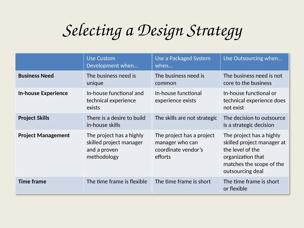
slide64. Selecting a Design Strategy Business need
In-house experience
Project skills
Project management
Time frame<br>
slide65. Selecting a Design Strategy<br>
slide66. Developing the Actual Design<br>
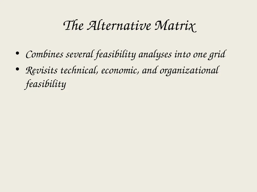
slide67. The Alternative Matrix Combines several feasibility analyses into one grid
Revisits technical, economic, and organizational feasibility<br>
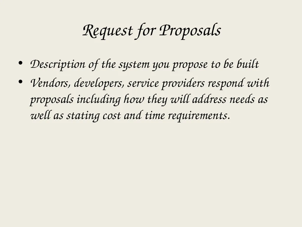
slide68. Request for Proposals Description of the system you propose to be built
Vendors, developers, service providers respond with proposals including how they will address needs as well as stating cost and time requirements.<br>
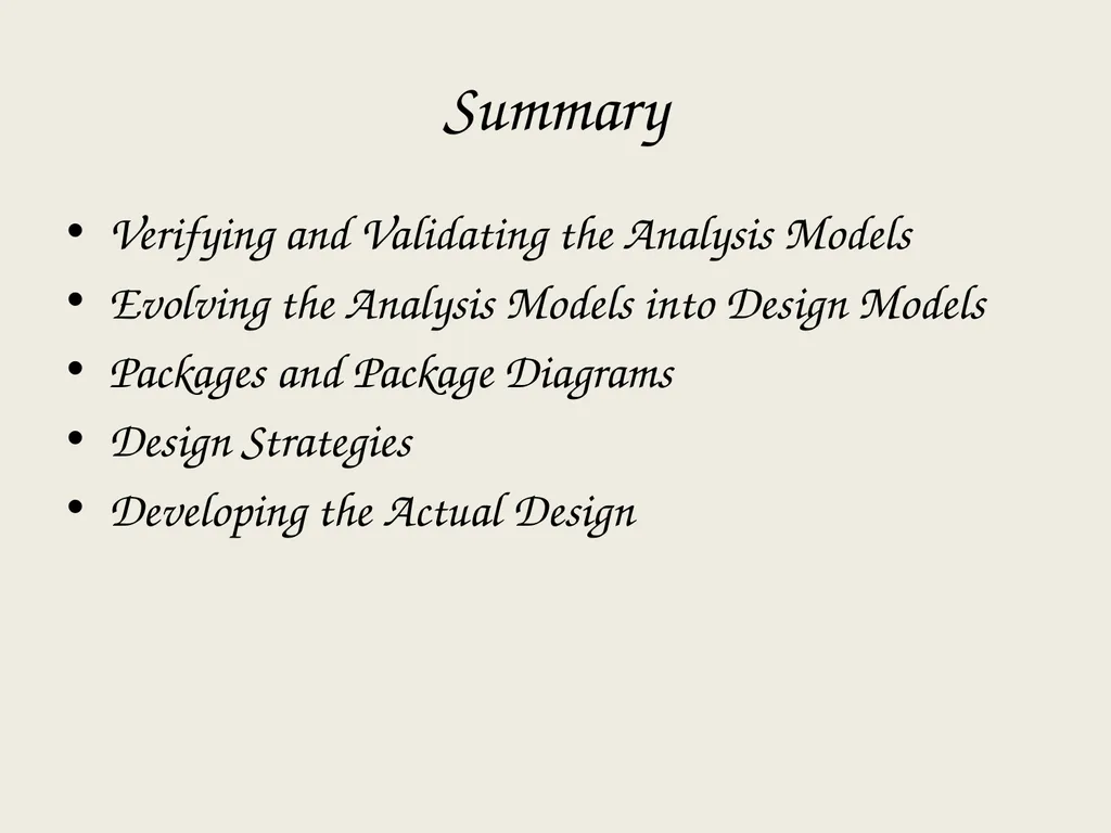
slide69. Summary Verifying and Validating the Analysis Models
Evolving the Analysis Models into Design Models
Packages and Package Diagrams
Design Strategies
Developing the Actual Design<br>
slide70. IBM Software Group ® Mastering Object-Oriented Analysis and Design with UML 2.0 Module 7: Identify Design Elements<br>
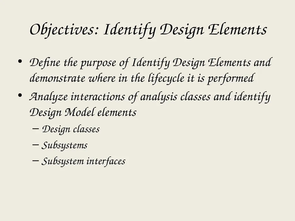
slide71. Objectives: Identify Design Elements Define the purpose of Identify Design Elements and demonstrate where in the lifecycle it is performed
Analyze interactions of analysis classes and identify Design Model elements
Design classes
Subsystems
Subsystem interfaces<br>
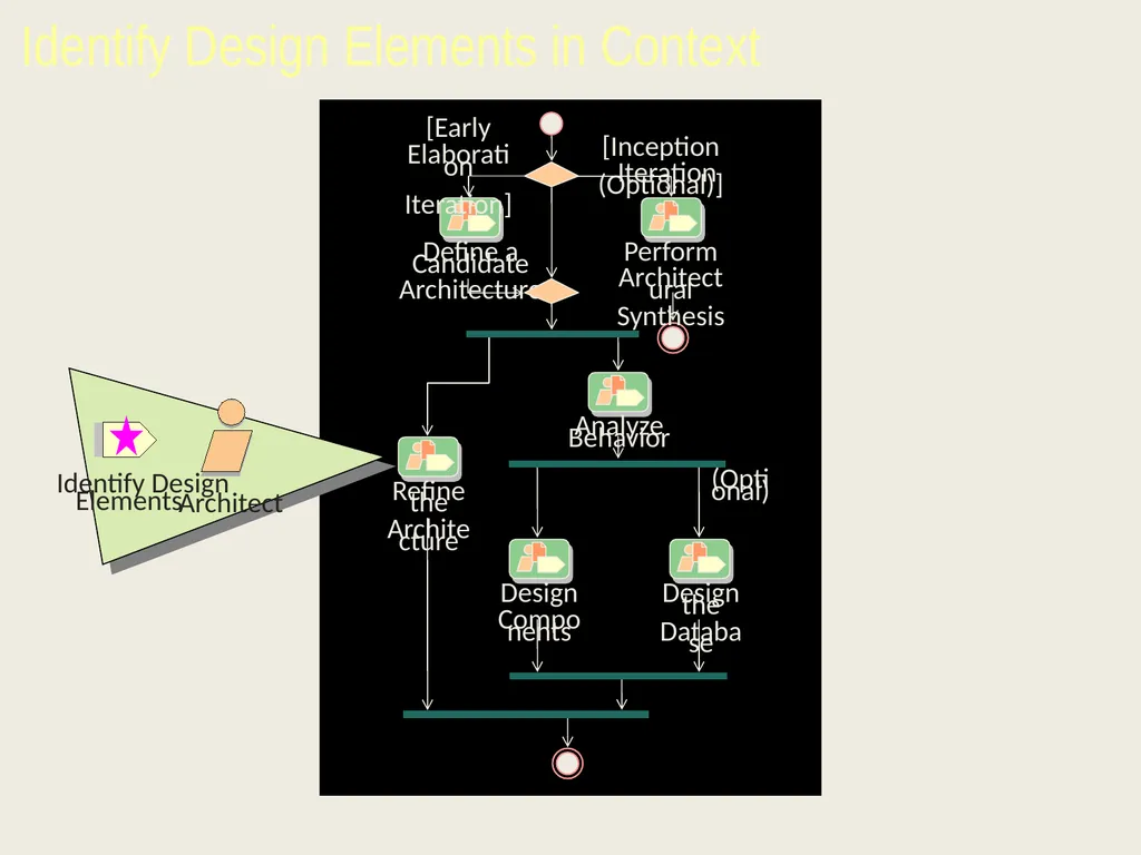
slide72. Identify Design Elements in Context<br>
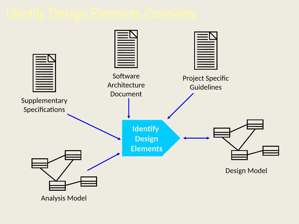
slide73. Identify
Design
Elements Identify Design Elements Overview<br>
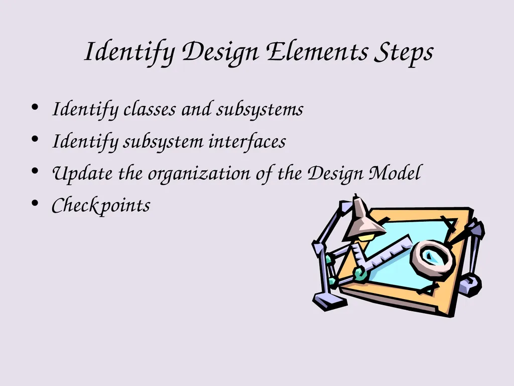
slide74. Identify Design Elements Steps Identify classes and subsystems
Identify subsystem interfaces
Update the organization of the Design Model
Checkpoints<br>
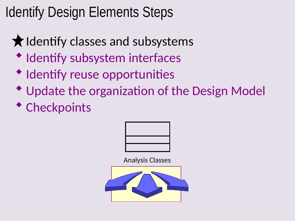
slide75. Identify Design Elements Steps Identify classes and subsystems
Identify subsystem interfaces
Identify reuse opportunities
Update the organization of the Design Model
Checkpoints Analysis Classes<br>
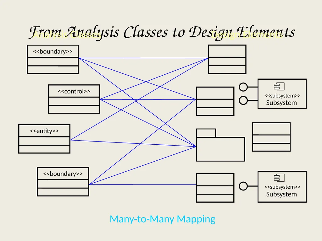
slide76. From Analysis Classes to Design Elements Analysis Classes Design Elements Many-to-Many Mapping Subsystem <<subsystem>> Subsystem <<subsystem>><br>
slide77. Identifying Design Classes An analysis class maps directly to a design class if:
It is a simple class
It represents a single logical abstraction
More complex analysis classes may
Split into multiple classes
Become a package
Become a subsystem (discussed later)
Any combination …<br>
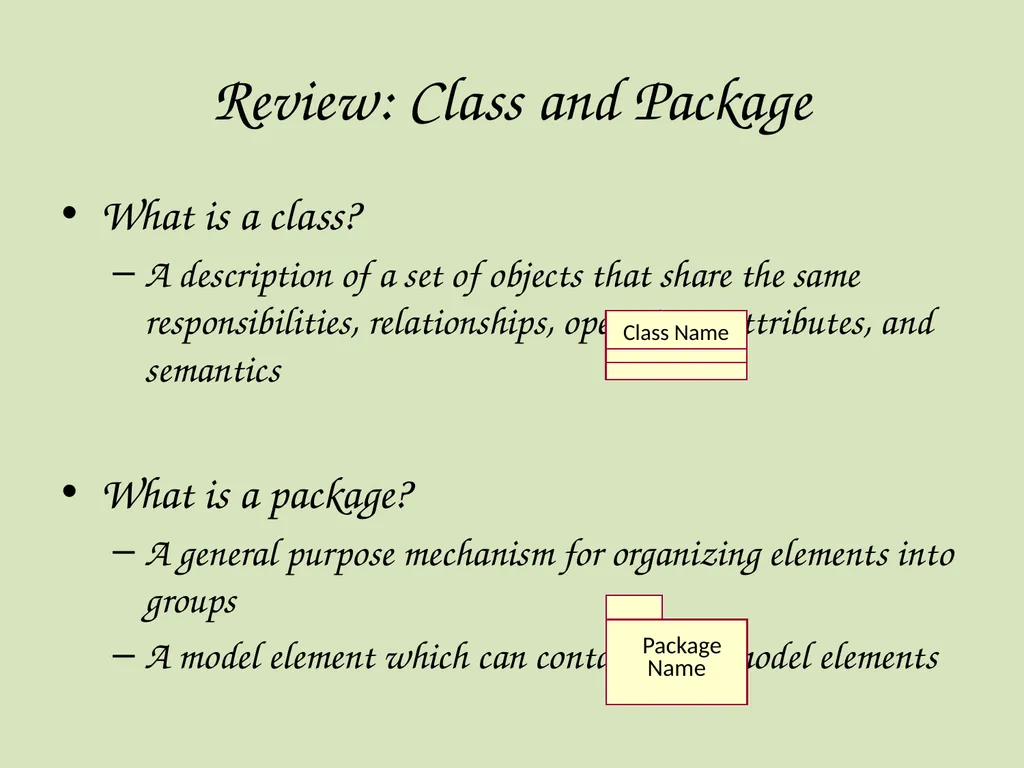
slide78. What is a class?
A description of a set of objects that share the same responsibilities, relationships, operations, attributes, and semantics
What is a package?
A general purpose mechanism for organizing elements into groups
A model element which can contain other model elements Review: Class and Package Package Name Class Name<br>
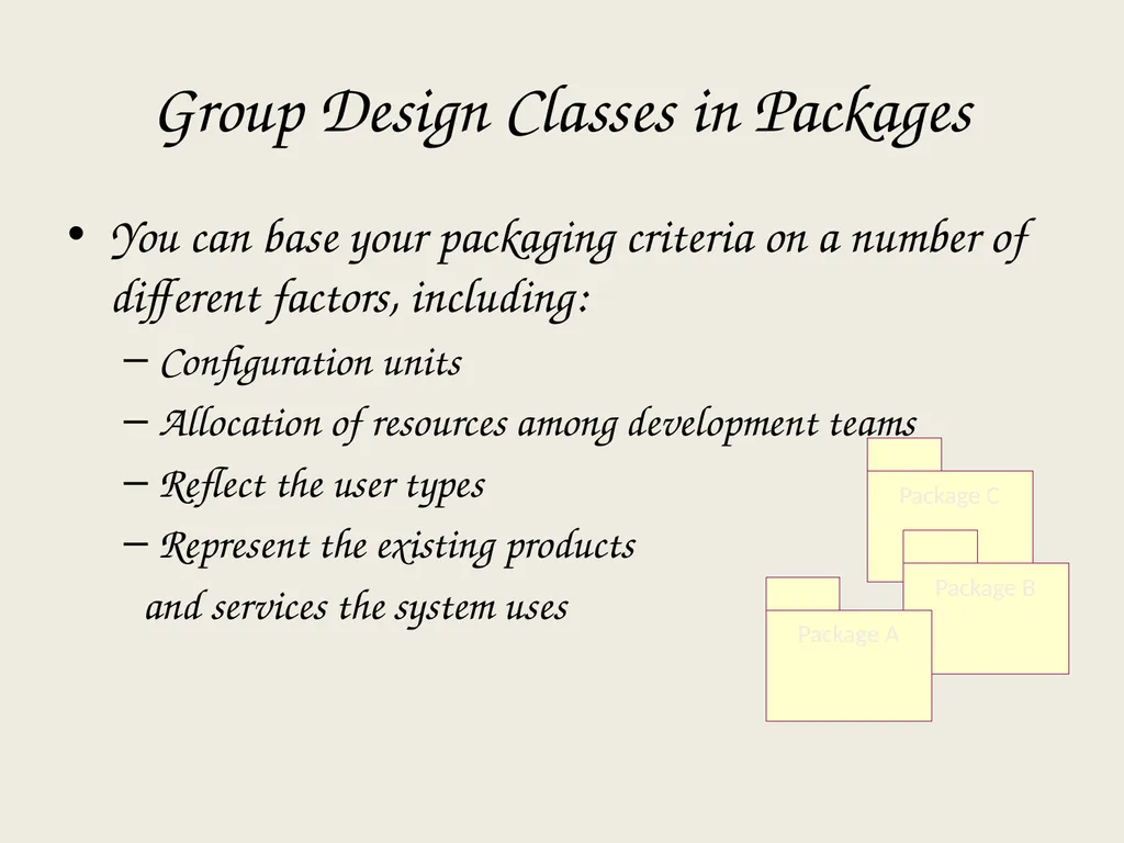
slide79. You can base your packaging criteria on a number of different factors, including:
Configuration units
Allocation of resources among development teams
Reflect the user types
Represent the existing products
and services the system uses Group Design Classes in Packages<br>
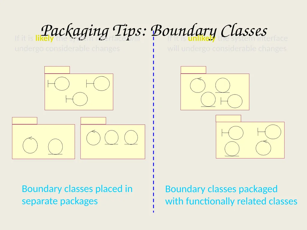
slide80. Packaging Tips: Boundary Classes If it is likely the system interface will undergo considerable changes Boundary classes placed in
separate packages If it is unlikely the system interface will undergo considerable changes Boundary classes packaged
with functionally related classes<br>
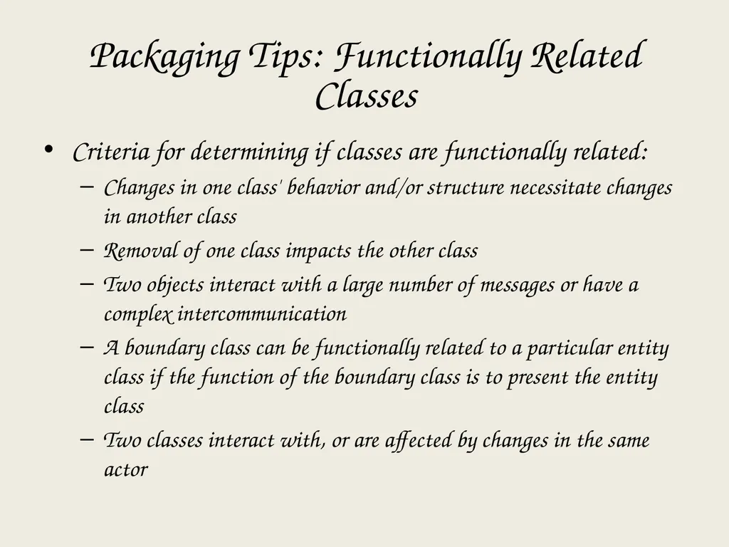
slide81. Packaging Tips: Functionally Related Classes Criteria for determining if classes are functionally related:
Changes in one class' behavior and/or structure necessitate changes in another class
Removal of one class impacts the other class
Two objects interact with a large number of messages or have a complex intercommunication
A boundary class can be functionally related to a particular entity class if the function of the boundary class is to present the entity class
Two classes interact with, or are affected by changes in the same actor<br>
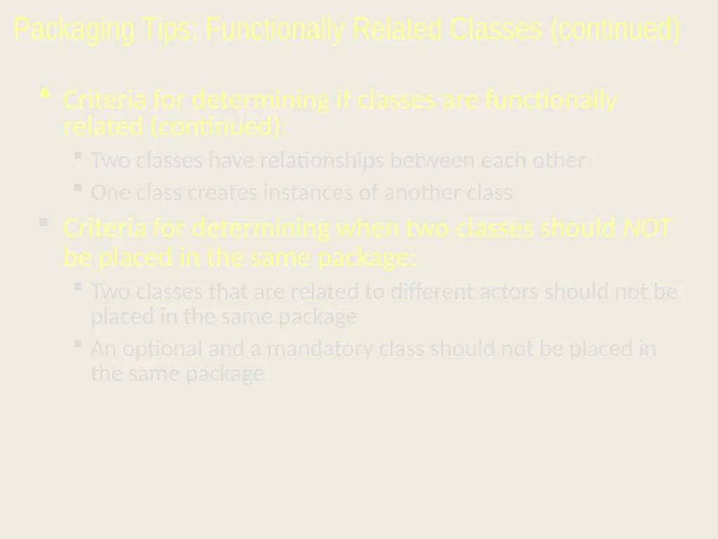
slide82. Packaging Tips: Functionally Related Classes (continued) Criteria for determining if classes are functionally related (continued):
Two classes have relationships between each other
One class creates instances of another class
Criteria for determining when two classes should NOT be placed in the same package:
Two classes that are related to different actors should not be placed in the same package
An optional and a mandatory class should not be placed in the same package<br>
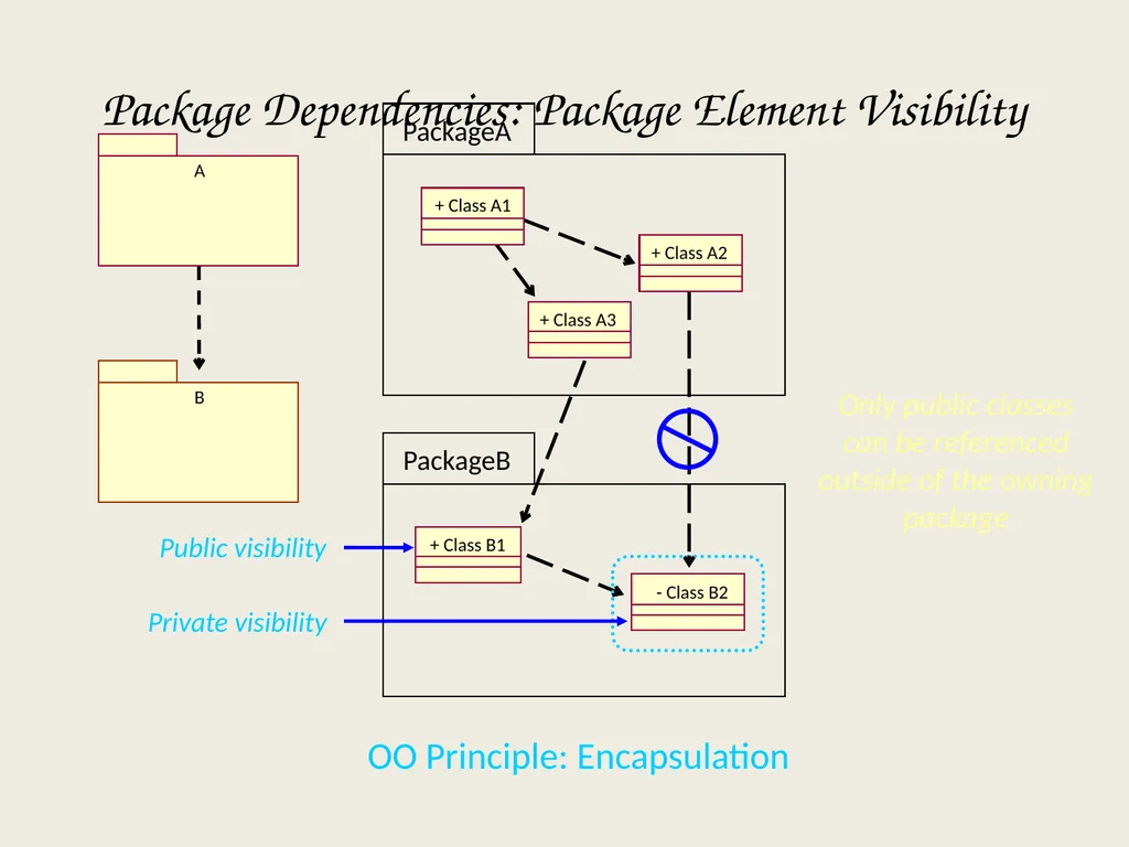
slide83. PackageB PackageA Public visibility Private visibility Only public classes can be referenced outside of the owning package OO Principle: Encapsulation Package Dependencies: Package Element Visibility A B + Class A1 + Class A2 + Class A3 + Class B1 - Class B2<br>
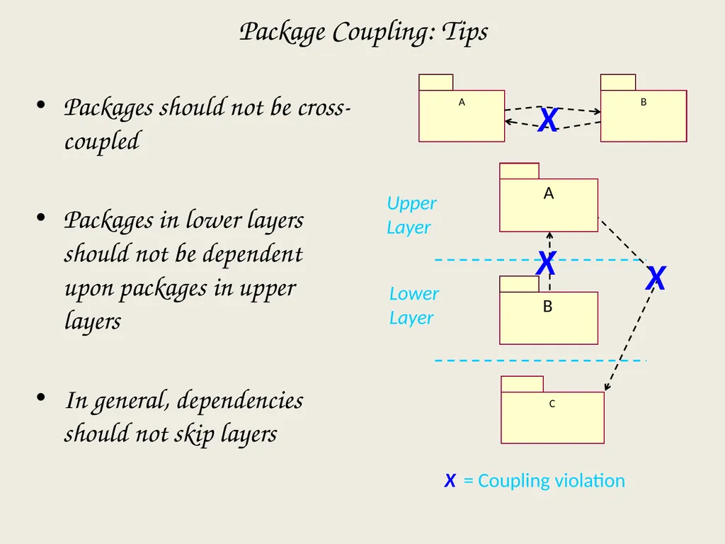
slide84. A B X Package Coupling: Tips Packages should not be cross-coupled
Packages in lower layers should not be dependent upon packages in upper layers
In general, dependencies should not skip layers A B Upper Layer Lower Layer C X X = Coupling violation X<br>
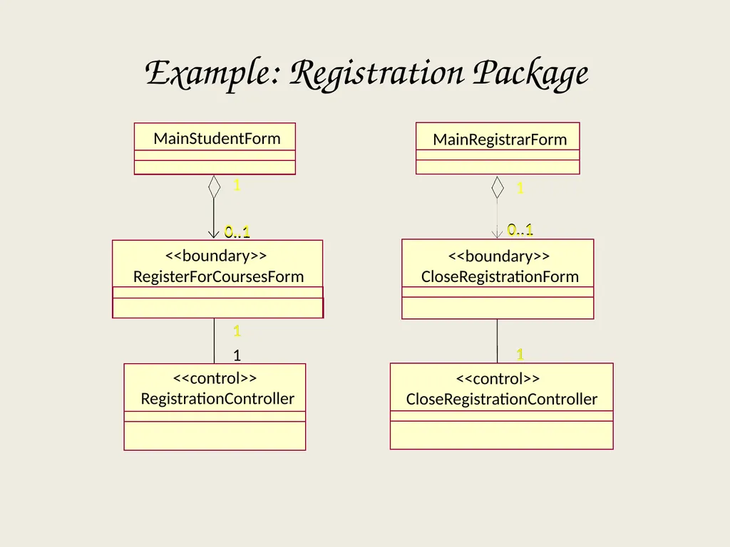
slide85. Example: Registration Package MainRegistrarForm 1 1 1 MainStudentForm 1 RegisterForCoursesForm <<boundary>> 0..1 0..1 1 1 CloseRegistrationForm <<boundary>> 0..1 0..1 CloseRegistrationController <<control>> RegistrationController <<control>> 1<br>
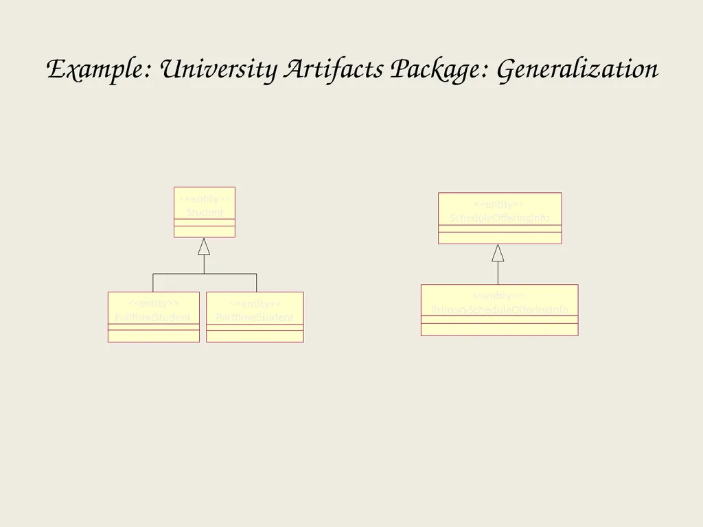
slide86. FulltimeStudent <<entity>> ParttimeStudent <<entity>> PrimaryScheduleOfferingInfo <<entity>> ScheduleOfferingInfo <<entity>> Example: University Artifacts Package: Generalization<br>
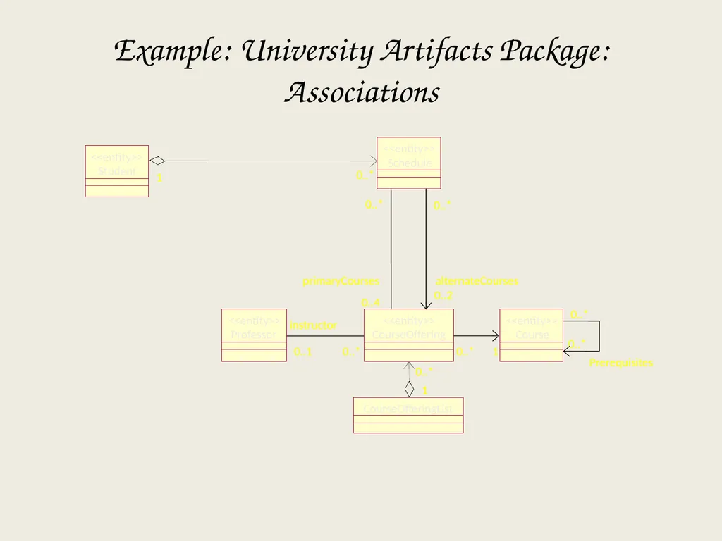
slide87. Professor <<entity>> CourseOffering <<entity>> CourseOfferingList 1 Prerequisites 0..* Course <<entity>> 0..* 1 instructor 0..1 0..* 0..* 0..* 0..* 0..4 primaryCourses 0..* 0..2 alternateCourses 0..* 1 Example: University Artifacts Package: Associations<br>
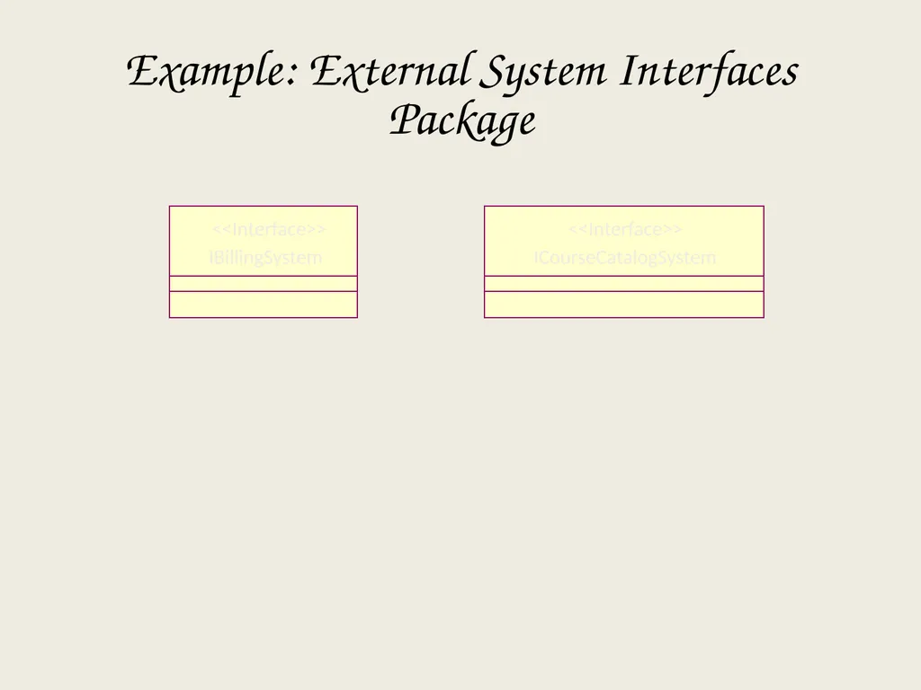
slide88. IBillingSystem <<Interface>> ICourseCatalogSystem <<Interface>> Example: External System Interfaces Package<br>
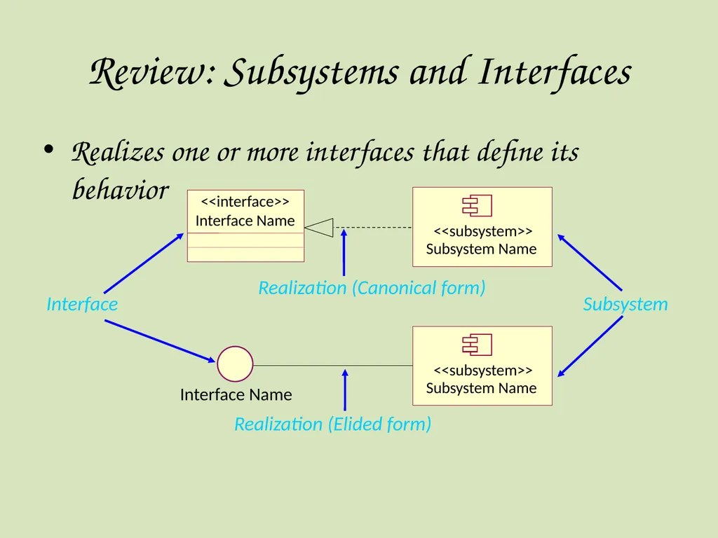
slide89. Realizes one or more interfaces that define its behavior Subsystem Review: Subsystems and Interfaces Interface Realization (Canonical form) Realization (Elided form) Interface Name Subsystem Name <<subsystem>> Interface Name <<interface>> Subsystem Name <<subsystem>><br>
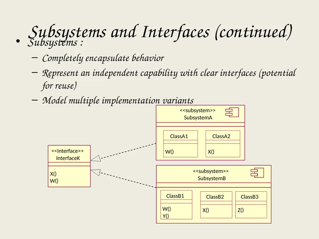
slide90. Subsystems and Interfaces (continued) Subsystems :
Completely encapsulate behavior
Represent an independent capability with clear interfaces (potential for reuse)
Model multiple implementation variants InterfaceK X() W() <<Interface>> SubsystemA <<subsystem>> SubsystemB <<subsystem>> ClassA1 W() ClassA2 X() ClassB1 W() Y() ClassB2 X() ClassB3 Z()<br>
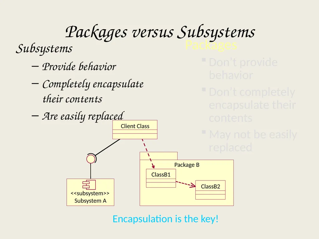
slide91. Encapsulation is the key! Packages versus Subsystems Subsystems
Provide behavior
Completely encapsulate their contents
Are easily replaced Subsystem A <<subsystem>> Package B ClassB1 ClassB2 Packages
Don’t provide behavior
Don’t completely encapsulate their contents
May not be easily replaced Client Class<br>
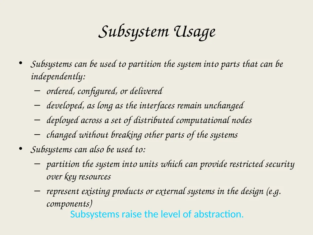
slide92. Subsystems raise the level of abstraction. Subsystem Usage Subsystems can be used to partition the system into parts that can be independently:
ordered, configured, or delivered
developed, as long as the interfaces remain unchanged
deployed across a set of distributed computational nodes
changed without breaking other parts of the systems
Subsystems can also be used to:
partition the system into units which can provide restricted security over key resources
represent existing products or external systems in the design (e.g. components)<br>
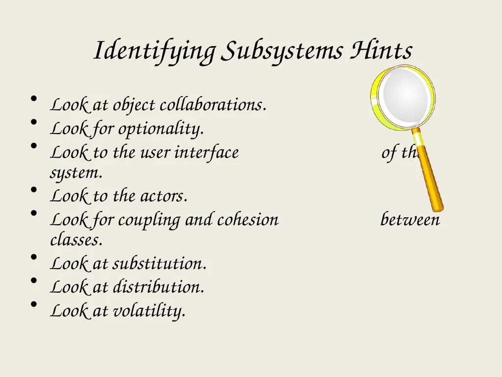
slide93. Identifying Subsystems Hints Look at object collaborations.
Look for optionality.
Look to the user interface of the system.
Look to the actors.
Look for coupling and cohesion between classes.
Look at substitution.
Look at distribution.
Look at volatility.<br>
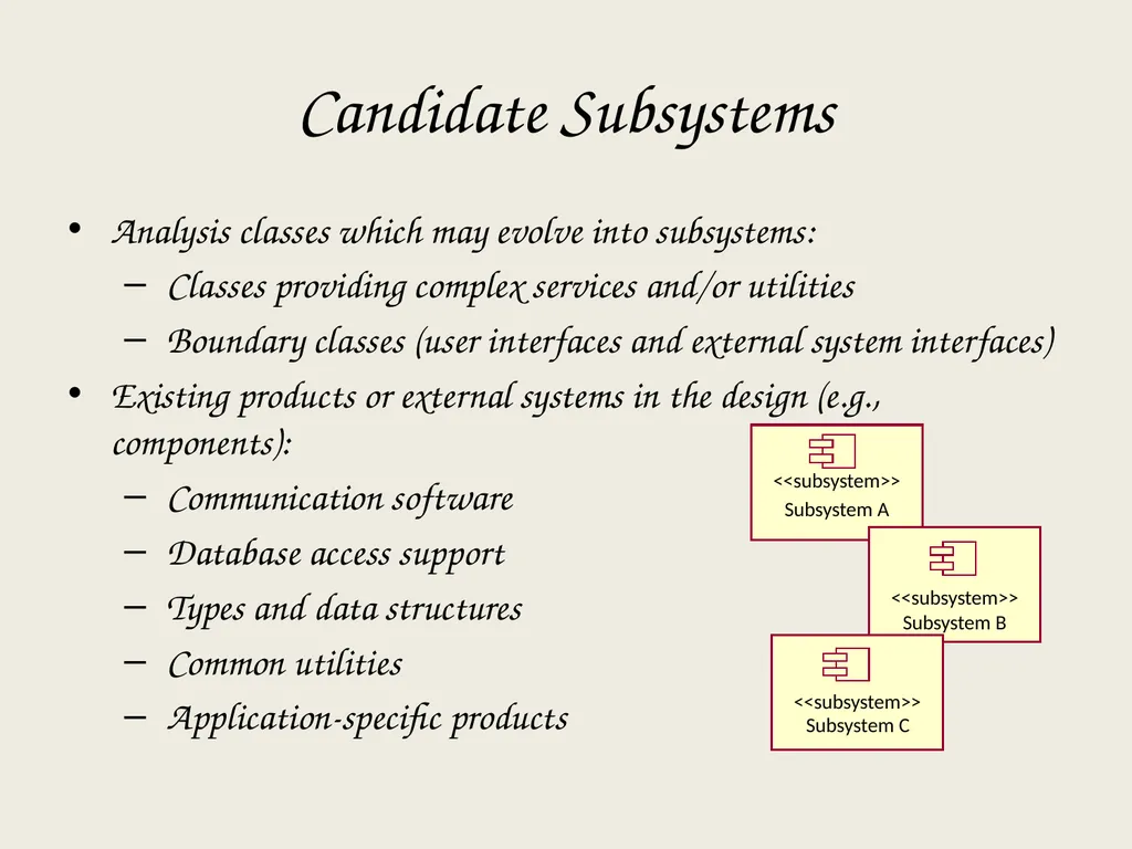
slide94. Analysis classes which may evolve into subsystems:
Classes providing complex services and/or utilities
Boundary classes (user interfaces and external system interfaces)
Existing products or external systems in the design (e.g., components):
Communication software
Database access support
Types and data structures
Common utilities
Application-specific products Candidate Subsystems Subsystem A <<subsystem>> Subsystem B <<subsystem>> Subsystem C <<subsystem>><br>
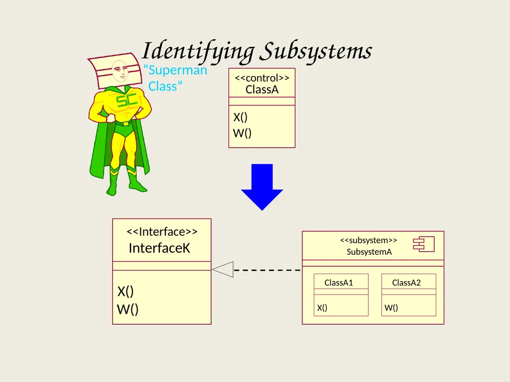
slide95. Identifying Subsystems <<control>> ClassA X() W() X() W() <<Interface>> InterfaceK SubsystemA <<subsystem>> ClassA1 X() ClassA2 W()<br>
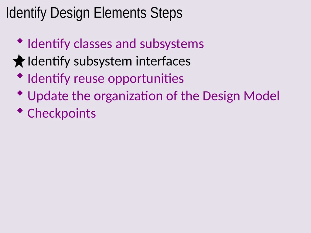
slide96. Identify Design Elements Steps Identify classes and subsystems
Identify subsystem interfaces
Identify reuse opportunities
Update the organization of the Design Model
Checkpoints<br>
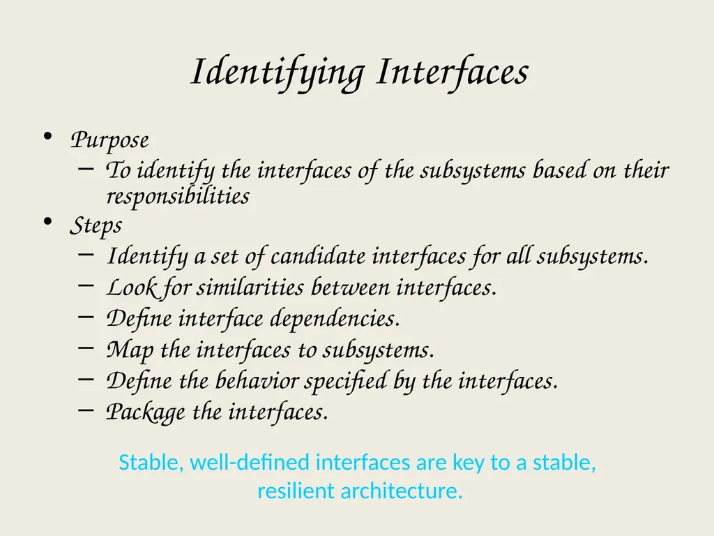
slide97. Stable, well-defined interfaces are key to a stable, resilient architecture. Identifying Interfaces Purpose
To identify the interfaces of the subsystems based on their responsibilities
Steps
Identify a set of candidate interfaces for all subsystems.
Look for similarities between interfaces.
Define interface dependencies.
Map the interfaces to subsystems.
Define the behavior specified by the interfaces.
Package the interfaces.<br>
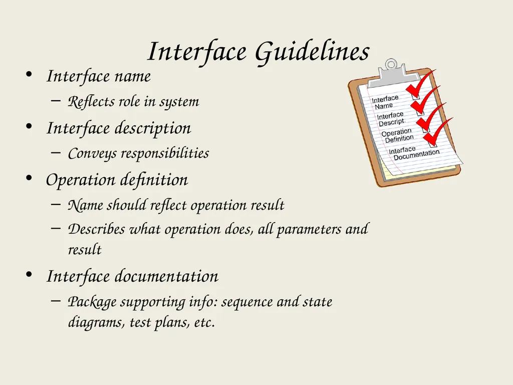
slide98. Interface Guidelines Interface name
Reflects role in system
Interface description
Conveys responsibilities
Operation definition
Name should reflect operation result
Describes what operation does, all parameters and result
Interface documentation
Package supporting info: sequence and state diagrams, test plans, etc.<br>
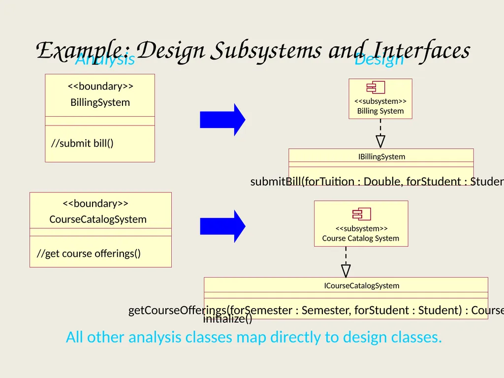
slide99. All other analysis classes map directly to design classes. Analysis Design Example: Design Subsystems and Interfaces BillingSystem //submit bill() <<boundary>> Billing System <<subsystem>> IBillingSystem submitBill(forTuition : Double, forStudent : Student) CourseCatalogSystem //get course offerings() <<boundary>> Course Catalog System <<subsystem>> ICourseCatalogSystem getCourseOfferings(forSemester : Semester, forStudent : Student) : CourseOfferingList initialize()<br>
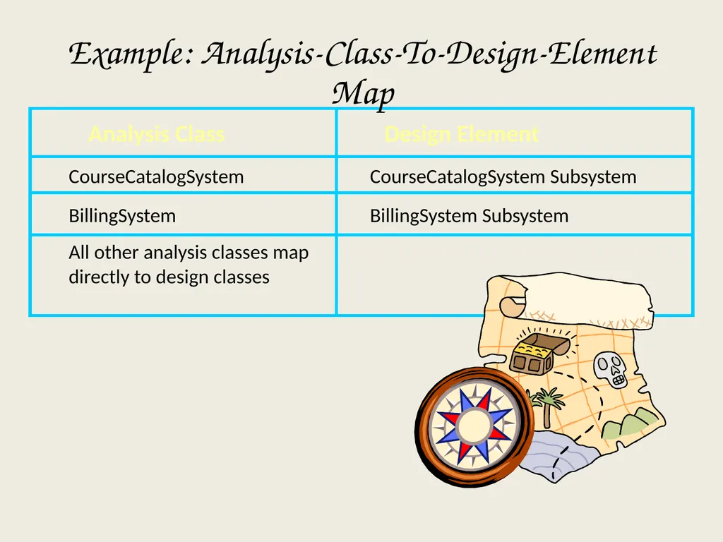
slide100. Analysis Class Design Element CourseCatalogSystem BillingSystem All other analysis classes map directly to design classes CourseCatalogSystem Subsystem BillingSystem Subsystem Example: Analysis-Class-To-Design-Element Map<br>
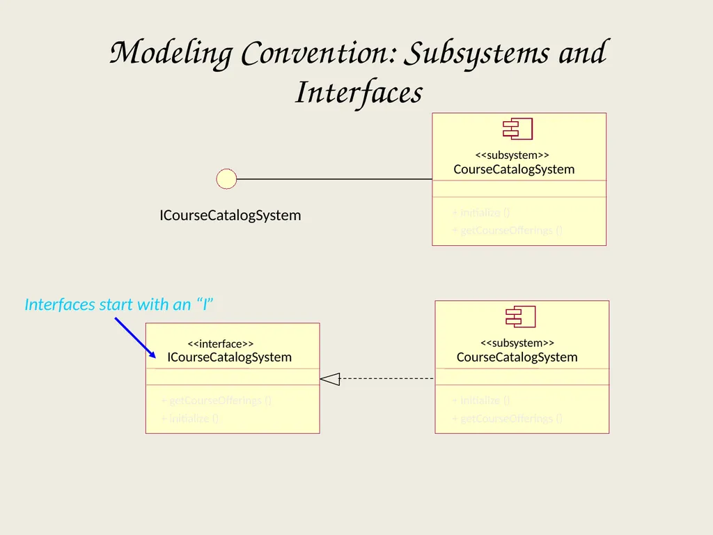
slide101. Interfaces start with an “I” Modeling Convention: Subsystems and Interfaces CourseCatalogSystem <<subsystem>> ICourseCatalogSystem + initialize ()
+ getCourseOfferings () CourseCatalogSystem <<subsystem>> + initialize ()
+ getCourseOfferings () ICourseCatalogSystem <<interface>> + getCourseOfferings ()
+ initialize ()<br>
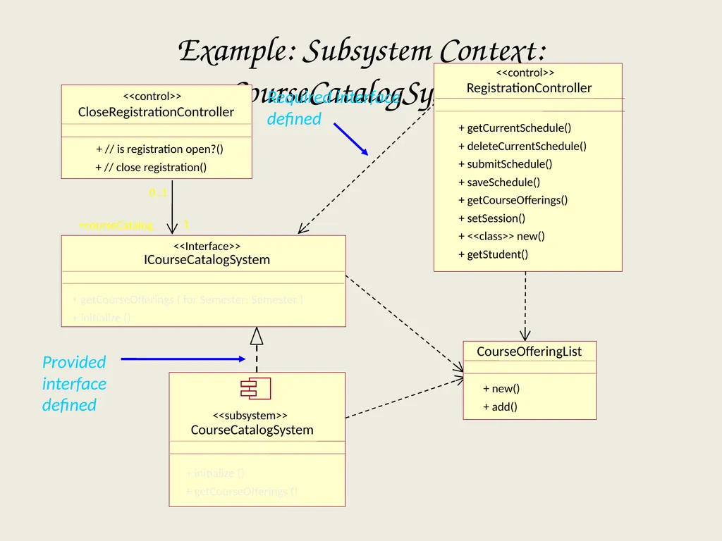
slide102. Example: Subsystem Context: CourseCatalogSystem Provided interface
defined ICourseCatalogSystem <<Interface>> CloseRegistrationController + // is registration open?() + // close registration() <<control>> 0..1 +courseCatalog CourseCatalogSystem <<subsystem>> + initialize ()
+ getCourseOfferings () + getCourseOfferings ( for Semester: Semester )
+ initialize () RegistrationController + getCurrentSchedule()
+ deleteCurrentSchedule()
+ submitSchedule()
+ saveSchedule()
+ getCourseOfferings()
+ setSession()
+ <<class>> new()
+ getStudent() <<control>> CourseOfferingList + new()
+ add() 1 Required interface
defined<br>
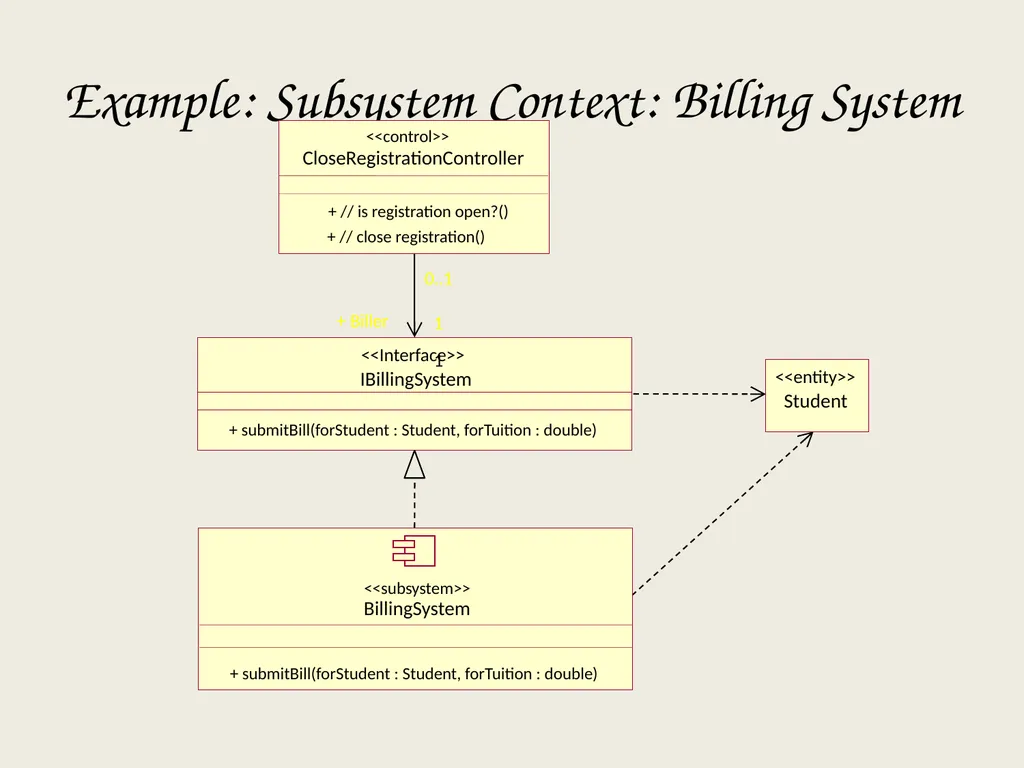
slide103. Example: Subsystem Context: Billing System IBillingSystem + submitBill(forStudent : Student, forTuition : double) <<Interface>> 1 0..1 + Biller 1 Student <<entity>> CloseRegistrationController + // is registration open?() + // close registration() <<control>> BillingSystem <<subsystem>> + submitBill(forStudent : Student, forTuition : double)<br>
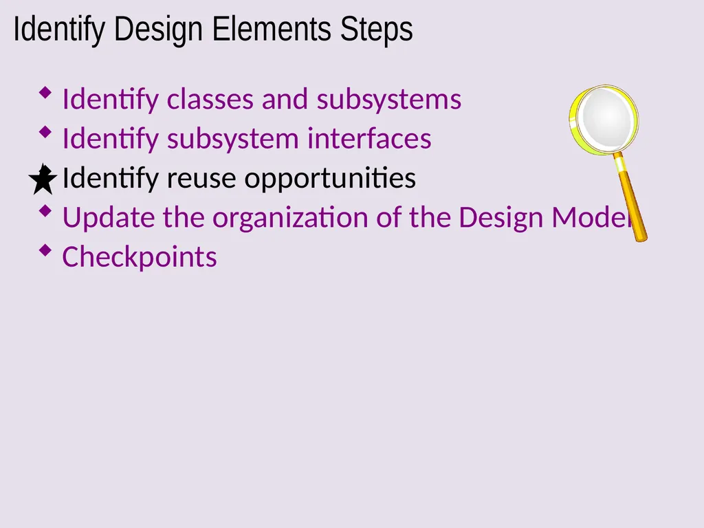
slide104. Identify Design Elements Steps Identify classes and subsystems
Identify subsystem interfaces
Identify reuse opportunities
Update the organization of the Design Model
Checkpoints<br>
slide105. Identification of Reuse Opportunities Purpose
To identify where existing subsystems and/or components can be reused based on their interfaces.
Steps
Look for similar interfaces
Modify new interfaces to improve the fit
Replace candidate interfaces with existing interfaces
Map the candidate subsystem to existing components<br>
slide106. Possible Reuse Opportunities Internal to the system being developed
Recognized commonality across packages and subsystems
External to the system being developed
Commercially available components
Components from a previously developed application
Reverse engineered components<br>
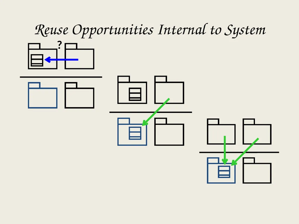
slide107. Reuse Opportunities Internal to System<br>
slide108. Identify classes and subsystems
Identify subsystem interfaces
Identify reuse opportunities
Update the organization of the Design Model
Checkpoints Identify Design Elements Steps<br>
slide109. Review: Typical Layering Approach General functionality Specific functionality Distinct application subsystems that make up an application — contains the value adding software developed by the organization. Business specific — contains a number of reusable subsystems specific to the type of business. Middleware — offers subsystems for utility classes and platform-independent services for distributed object computing in heterogeneous environments and so on. System software — contains the software for the actual infrastructure such as operating systems, interfaces to specific hardware, device drivers, and so on. Application Business-Specific Middleware System Software<br>
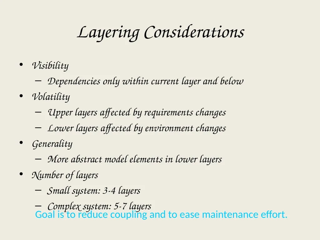
slide110. Goal is to reduce coupling and to ease maintenance effort. Layering Considerations Visibility
Dependencies only within current layer and below
Volatility
Upper layers affected by requirements changes
Lower layers affected by environment changes
Generality
More abstract model elements in lower layers
Number of layers
Small system: 3-4 layers
Complex system: 5-7 layers<br>
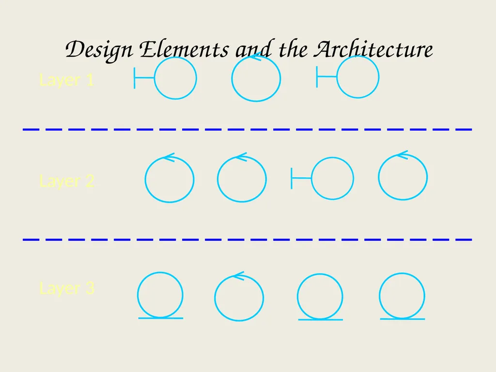
slide111. Layer 1 Layer 2 Layer 3 Design Elements and the Architecture<br>
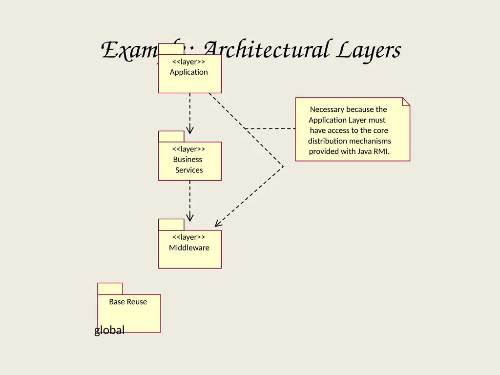
slide112. Example: Architectural Layers Middleware <<layer>> Base Reuse global Application <<layer>> Business Services <<layer>> Necessary because the Application Layer must have access to the core distribution mechanisms provided with Java RMI.<br>
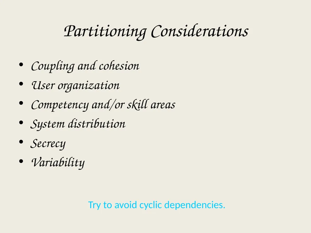
slide113. Partitioning Considerations Coupling and cohesion
User organization
Competency and/or skill areas
System distribution
Secrecy
Variability Try to avoid cyclic dependencies.<br>
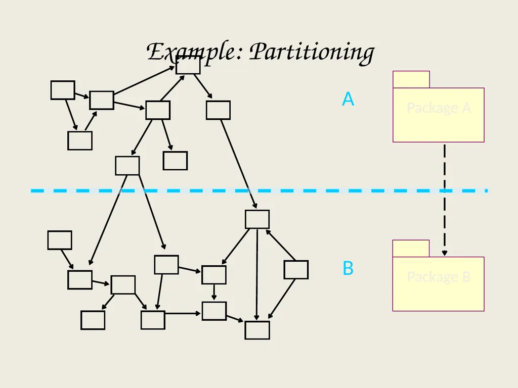
slide114. B A Package A Package B Example: Partitioning<br>
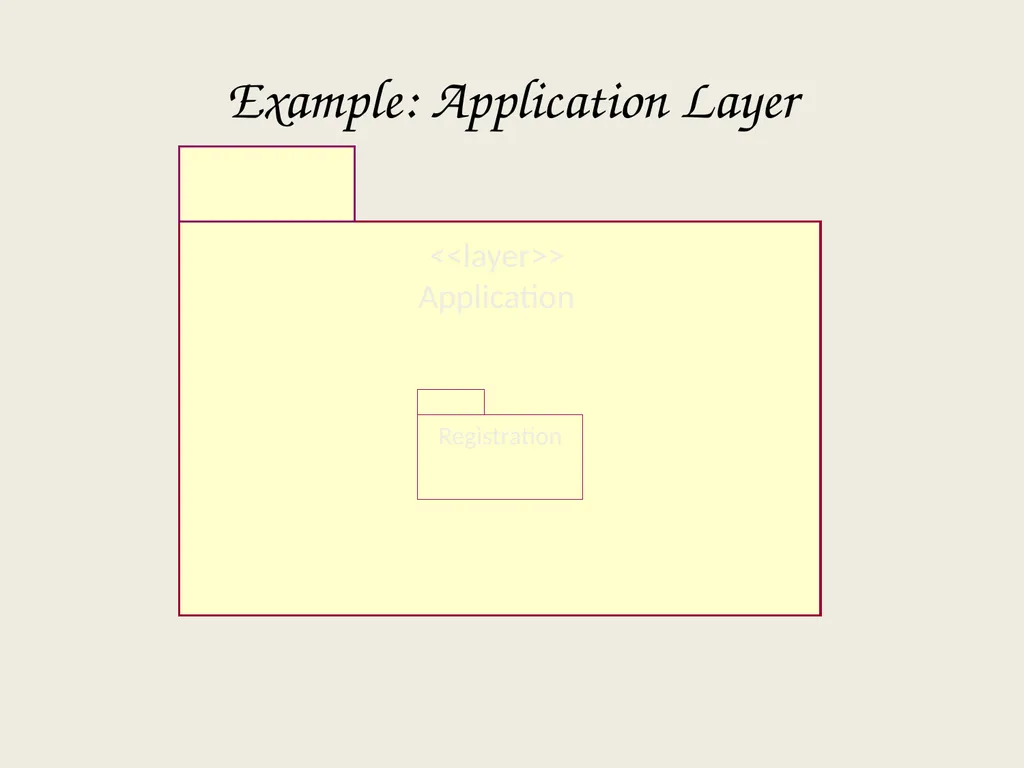
slide115. Registration <<layer>>
Application Example: Application Layer<br>
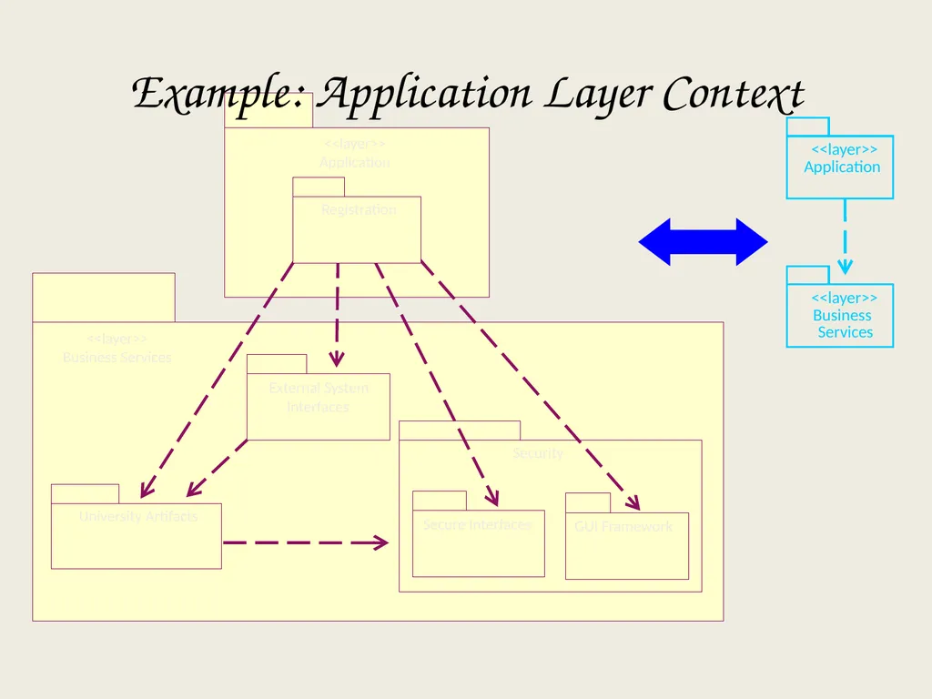
slide116. Application <<layer>> Business Services <<layer>> <<layer>>
Application <<layer>>
Business Services Example: Application Layer Context Registration<br>
slide117. Example: Business Services Layer CourseCatalogSystem <<subsystem>> External System Interfaces University Artifacts ObjectStore Support <<layer>> Business Services GUI
Framework Secure
Interfaces Security <<subsystem>>
Security
Manager BillingSystem <<subsystem>><br>
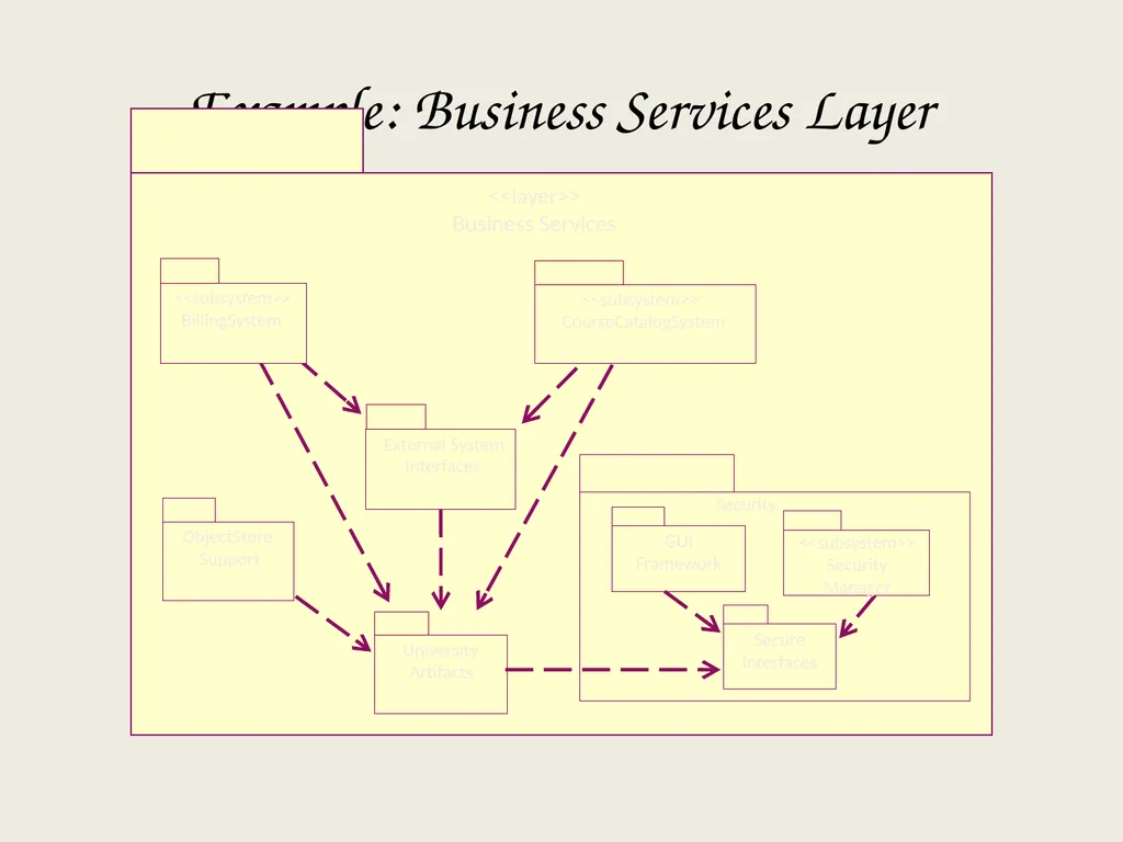
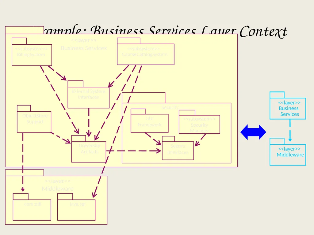
slide118. Middleware <<layer>> Business Services <<layer>> Example: Business Services Layer Context java.sql com.odi <<layer>> Middleware BillingSystem <<subsystem>> CourseCatalogSystem <<subsystem>> External System Interfaces University Artifacts ObjectStore Support <<layer>> Business Services GUI
Framework Secure
Interfaces Security <<subsystem>>
Security
Manager<br>
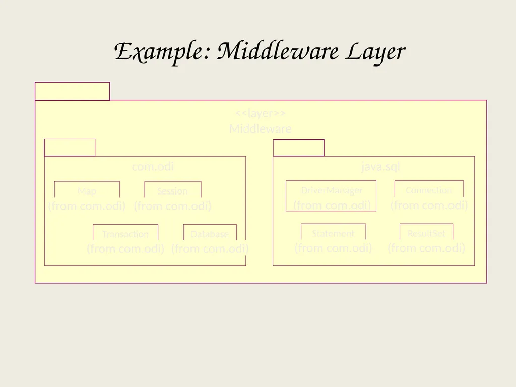
slide119. com.odi Database (from com.odi) Session (from com.odi) Transaction (from com.odi) Map (from com.odi) java.sql ResultSet (from com.odi) Connection (from com.odi) Statement (from com.odi) Example: Middleware Layer <<layer>>
Middleware<br>
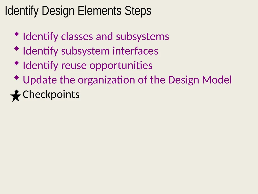
slide120. Identify Design Elements Steps Identify classes and subsystems
Identify subsystem interfaces
Identify reuse opportunities
Update the organization of the Design Model
Checkpoints<br>
slide121. Checkpoints General
Does it provide a comprehensive picture of the services of different packages?
Can you find similar structural solutions that can be used more widely in the problem domain?
Layers
Are there more than seven layers?
Subsystems
Is subsystem partitioning done in a logically consistent way across the entire model?<br>
slide122. Checkpoints (continued) Packages
Are the names of the packages descriptive?
Does the package description match with the responsibilities of contained classes?
Do the package dependencies correspond to the relationships between the contained classes?
Do the classes contained in a package belong there according to the criteria for the package division?
Are there classes or collaborations of classes within a package that can be separated into an independent package?
Is the ratio between the number of packages and the number of classes appropriate?<br>
slide123. Checkpoints (continued) Classes
Does the name of each class clearly reflect the role it plays?
Is the class cohesive (i.e., are all parts functionally coupled)?
Are all class elements needed by the use-case realizations?
Do the role names of the aggregations and associations accurately describe the relationship?
Are the multiplicities of the relationships correct?<br>
slide124. Review: Identify Design Elements What is the purpose of Identify Design Elements?
What is an interface?
What is a subsystem? How does it differ from a package?
What is a subsystem used for, and how do you identify them?
What are some layering and partitioning considerations?<br>
Copyright to the original slides resides with IBM/Rational. They are used here, in this course, under password protection limited to students enrolled in the course, with permission of the owners, but are not to be published or further distributed.<br>
slide2. What Is Architecture? Software architecture encompasses a set of significant decisions about the organization of a software system.
Selection of the structural elements and their interfaces by which a system is composed
Behavior as specified in collaborations among those elements
Composition of these structural and behavioral elements into larger subsystems
Architectural style that guides this organization Grady Booch, Philippe Kruchten, Rich Reitman, Kurt Bittner; Rational
(derived from Mary Shaw)<br>
slide3. Architecture Constrains Design and Implementation Architecture involves a set of strategic design decisions, rules or patterns that constrain design and construction. Architecture decisions are the most fundamental decisions, and changing them will have significant effects. Architecture Design Implementation Code`1`<br>
slide4. Software Architecture: The “4+1 View” Model Process View Deployment View Logical View Use-Case View Implementation View End-user Functionality Programmers Software management Performance, scalability, throughput System integrators System topology, delivery,
installation, communication System engineering Analysts/Designers Structure<br>
slide5. Analysis and Design Workflow Analysis Design [Early Elaboration Iteration] [Inception Iteration (Optional)] Define a Candidate
Architecture Perform
Architectural
Synthesis Analyze Behavior Refine the
Architecture Design
Components Design the
Database (Optional)<br>
slide6. Analysis and Design Activity Overview Architect Designer<br>
slide7. Software Architect’s Responsibilities Architect The Software Architect leads and coordinates technical activities and artifacts. Deployment Model Implementation Model<br>
slide8. Designer’s Responsibilities Designer The designer must know use-case modeling techniques, system requirements, and software design techniques.<br>
slide9. Review: Analysis and Design Is Use-Case Driven Use cases defined for a system are the basis for the entire development process.
Benefits of use cases:
Concise, simple, and understandable by a wide range of stakeholders.
Help synchronize the content of different models. Withdraw Money Check Balance<br>
slide10. What Is a Use-Case Realization? Use Case Communication Diagrams Use-Case Model Design Model Use Case Use-Case Realization Sequence Diagrams (Traceability)<br>
slide11. Analysis and Design in an Iterative Process Iteration n Iteration n + 1 Start of iteration End of iteration<br>
slide12. Review What is the purpose of the Analysis and Design Discipline?
What are the input and output artifacts?
Name and briefly describe the 4+1 Views of Architecture.
What is the difference between Analysis and Design?
What is architecture?<br>
slide13. ARCHITECTURAL ANALYSIS<br>
slide14. KEY CONCEPTS<br>
slide15. Architectural Analysis in Context [Early
Elaboration
Iteration] [Inception
Iteration (Optional)] Define a Candidate
Architecture Perform
Architectural
Synthesis Analyze Behavior Refine the
Architecture Design
Components Design the
Database (Optional) Architecture Analysis`<br>
slide16. Architectural Analysis Overview Architectural
Analysis Deployment Model<br>
slide17. Architectural Analysis Steps Key Concepts
Define the High-Level Organization of Subsystems
Identify Analysis mechanisms
Identify Key Abstractions
Create Use-Case Realizations
Checkpoints<br>
slide18. A package is a general-purpose mechanism for organizing elements into groups.
It is a model element that can contain other model elements.
A package can be used:
To organize the model under development.
As a unit of configuration management.
To cope with complexity. Review: What Is a Package? UniversityArtifacts<br>
slide19. Packages can be related to one another using a dependency relationship.
Dependency Implications
Changes to the Supplier package may affect the Client package.
The Client package cannot be reused independently because it depends on the Supplier package. Package Relationships: Dependency Dependency relationship<br>
slide20. Package Diagram for 5 Layers A package diagram shows packages only<br>
slide21. C A B Hierarchy should be acyclic A B C A' Circular dependencies make it impossible to reuse one package without the other. Avoiding Circular Dependencies A B<br>
slide22. Architectural Analysis Steps Key Concepts
Define the High-Level Organization of Subsystems
Identify Analysis mechanisms
Identify Key Abstractions
Create Use-Case Realizations
Checkpoints<br>
slide23. Patterns and Frameworks Pattern
Provides a common solution to a common problem in a context
Analysis/Design pattern
Provides a solution to a narrowly-scoped technical problem
Provides a fragment of a solution, or a piece of the puzzle
Framework
Defines the general approach to solving the problem
Provides a skeletal solution, whose
details may be Analysis/Design patterns<br>
slide24. Structural Aspect Behavioral Aspect What Is a Design Pattern? A solution to a common design problem.
Describes a common design problem
Describes the solution to the problem
Discusses the results and trade-offs of applying the pattern
Provides the capability to reuse successful designs. Parameterized Collaboration<br>
slide25. What Is an Architectural Pattern? An architectural pattern expresses a fundamental structural organization schema for software systems. It provides a set of predefined subsystems, specifies their responsibilities, and includes rules and guidelines for organizing the relationships between them – Buschman et al, “Pattern-Oriented Software Architecture — A System of Patterns”
Layers
Model-view-controller (M-V-C)
Pipes and filters
Blackboard<br>
slide26. Evolving the Analysis Models into Design Models<br>
slide27. Factoring Creating modules that account for similarities and differences between units of interest
New classes
Generalization
Aggregation
Abstracting
Refinement<br>
slide28. Partitions and Collaborations Creating “subsystems” or larger units
Grouping units that collaborate
May have collaboration among units or partitions
The more messages or contracts between objects, the more likely they are in the same partition<br>
slide29. Layers Consider system environment information to help evolve the analysis model
Model-view-controller (MVC) architecture
Separating application logic from user interface logic<br>
slide30. Typical Layering Approach General functionality Specific functionality Distinct application subsystems that make up an application — contains the value adding software developed by the organization. Business specific — contains a number of reusable subsystems specific to the type of business. Middleware — offers subsystems for utility classes and platform-independent services for distributed object computing in heterogeneous environments and so on. System software — contains the software for the actual infrastructure such as operating systems, interfaces to specific hardware, device drivers, and so on. Application Subsystems Business-Specific Middleware System Software<br>
slide31. Example: Layers Application Layer 7 Layer 6 Layer 5 Layer 4 Layer 3 Layer 2 Layer 1 Provides miscellaneous protocols for common activities Structure information and attaches semantics Provides dialog control and synchronization facilities Breaks messages into packets and guarantees delivery Selects a route from send to receiver Detects and corrects errors in bit sequences Transmits bits: velocity, bit-code, connection, etc.<br>
slide32. Architectural Pattern: Layers Equipment and
customer-specific
code Processes and other application code Major abstractions, classes, etc. Mechanisms,
services H/W specific code, O/S specific code, general-purpose code (for example, ORB, MQS) 5 4 3 2 1 Application Application
Framework Infrastructure<br>
slide33. Dennis et al. : 5 Layers Foundation
Problem Domain
Data Management
Human-Computer Interaction
Physical Architecture Are these in a logical order?<br>
slide34. Layering Considerations Level of abstraction
Group elements at the same level of abstraction
Separation of concerns
Group like things together
Separate disparate things
Application vs. domain model elements
Resiliency
Loose coupling
Concentrate on encapsulating change
User interface, business rules, and retained data tend to have a high potential for change<br>
slide35. Modeling Architectural Layers Architectural layers can be modeled using stereotyped packages.
<<layer>> stereotype Package Name <<layer>><br>
slide36. Class <<stereotype>> What Are Stereotypes? Stereotypes define a new model element in terms of another model element.
Sometimes you need to introduce new things that speak the language of your domain and look like primitive building blocks. Stereotype<br>
slide37. Example: High-Level Organization of the Model Application <<layer>> Business Services <<layer>><br>
slide38. Architectural Analysis Steps Key Concepts
Define the High-Level Organization of the model
Identify Analysis mechanisms
Identify Key Abstractions
Create Use-Case Realizations
Checkpoints<br>
slide39. Mechanisms COTS Products Databases IPC Technology, etc. “realized by client classes using” “responsible for” “constrained by” Required Functionality Implementation Environment What Are Architectural Mechanisms?<br>
slide40. Architectural Mechanism Categories Analysis mechanisms (conceptual)
Design mechanisms (concrete)
Implementation mechanisms (actual)<br>
slide41. Why Use Analysis Mechanisms? Oh no! I found a group of classes that has persistent data. How am I supposed to design these things if I don’t even know what database we are going to be using? That is why we have a persistence analysis mechanism. We don’t know enough yet, so we can bookmark it and come back to it later. Analysis mechanisms are used during analysis to reduce the complexity of analysis and to improve its consistency by providing designers with a shorthand representation for complex behavior.<br>
slide42. Sample Analysis Mechanisms Persistency
Communication (IPC and RPC)
Message routing
Distribution
Transaction management
Process control and synchronization (resource contention)
Information exchange, format conversion
Security
Error detection / handling / reporting
Redundancy
Legacy Interface<br>
slide43. Examples of Analysis Mechanism Characteristics Persistency mechanism
Granularity
Volume
Duration
Access mechanism
Access frequency (creation/deletion, update, read)
Reliability
Inter-process Communication mechanism
Latency
Synchronicity
Message size
Protocol<br>
slide44. Example: Analysis Mechanism Characteristics (continued) Legacy interface mechanism
Latency
Duration
Access mechanism
Access frequency
Security mechanism
Data granularity
User granularity
Security rules
Privilege types
Others<br>
slide45. Collect all analysis mechanisms in a list
Draw a map of classes to analysis mechanisms
Identify characteristics of analysis mechanisms
Model using collaborations Describing Analysis Mechanisms Classes Parsing Authentication Communication Persistency Analysis Mechanisms Flight Aircraft Mission Schedule Route Load<br>
slide46. Example: Course Registration Analysis Mechanisms Security Legacy Interface Persistence Distribution<br>
slide47. Architectural Analysis Steps Key Concepts
Define the High-Level Organization of the model
Identify Analysis mechanisms
Identify Key Abstractions
Create Use-Case Realizations
Checkpoints<br>
slide48. What Are Key Abstractions? A key abstraction is a concept, normally uncovered in Requirements, that the system must be able to handle
Sources for key abstractions Domain knowledge
Requirements
Glossary
Domain Model, or the Business Model (if one exists)<br>
slide49. Defining Key Abstractions Define analysis classes
Model analysis classes and relationships on class diagrams
Include a brief description of an analysis class
Map analysis classes to necessary analysis mechanisms<br>
slide50. Example: Key Abstractions<br>
slide51. Architectural Analysis Steps Key Concepts
Define the High-Level Organization of the model
Identify Analysis mechanisms
Identify Key Abstractions
Create Use-Case Realizations
Checkpoints<br>
slide52. Review: What is a Use-Case Realization? Use Case Communication Diagrams Use-Case Model Design Model Use Case Use-Case Realization Sequence Diagrams<br>
slide53. The Value of Use-Case Realizations Provides traceability from Analysis and Design back to Requirements
The Architect creates the Use-Case Realization Analysis & Design
(Design Model) Requirements
(Use-Case Model) Use-Case realization<br>
slide54. Architectural Analysis Steps Key Concepts
Define the High-Level Organization of the model
Identify Analysis mechanisms
Identify Key Abstractions
Create Use-Case Realizations
Checkpoints<br>
slide55. Checkpoints General
Is the package partitioning and layering done in a logically consistent way?
Have the necessary analysis mechanisms been identified?
Packages
Have we provided a comprehensive picture of the services of the packages in upper-level layers?<br>
slide56. Checkpoints (continued) Classes
Have the key entity classes and their relationships been identified and accurately modeled?
Does the name of each class clearly reflect the role it plays?
Are the key abstractions/classes and their relationships consistent with the Business Model, Domain Model, Requirements, Glossary, etc.?<br>
slide57. Review: Architectural Analysis What is the purpose of Architectural Analysis?
What is a package?
What is a layered architecture? Give examples of typical layers.
What are analysis mechanisms? Give examples.
What key abstractions are identified during Architectural Analysis? Why are they identified here?<br>
slide58. Building Package Diagrams Set the context
Cluster classes together based on shared relationships
Model clustered classes as a package
Identify dependency relationships among packages
Place dependency relationships between packages<br>
slide59. Design Strategies<br>
slide60. Custom Development Allows for meeting highly specialized requirements
Allows flexibility and creativity in solving problems
Easier to change components
Builds personnel skills
May tax firm’s resources
May add significant risk<br>
slide61. Packaged Software Software already written
May be more efficient
May be more thoroughly tested and proven
May range from components to tools to whole enterprise systems
Must accept functionality provided
May require change in how the firm does business
May require significant “customization” or “workarounds”<br>
slide62. System Integration The process of combining packages, legacy systems, and new software
Key challenge is integrating data
Write data in the same format
Revise existing data formats
Develop “object wrappers”<br>
slide63. Outsourcing Hire external firm to create system
May have more skills
May extend existing resources
Never outsource what you don’t understand
Carefully choose vendor
Prepare contract and payment style carefully<br>
slide64. Selecting a Design Strategy Business need
In-house experience
Project skills
Project management
Time frame<br>
slide65. Selecting a Design Strategy<br>
slide66. Developing the Actual Design<br>
slide67. The Alternative Matrix Combines several feasibility analyses into one grid
Revisits technical, economic, and organizational feasibility<br>
slide68. Request for Proposals Description of the system you propose to be built
Vendors, developers, service providers respond with proposals including how they will address needs as well as stating cost and time requirements.<br>
slide69. Summary Verifying and Validating the Analysis Models
Evolving the Analysis Models into Design Models
Packages and Package Diagrams
Design Strategies
Developing the Actual Design<br>
slide70. IBM Software Group ® Mastering Object-Oriented Analysis and Design with UML 2.0 Module 7: Identify Design Elements<br>
slide71. Objectives: Identify Design Elements Define the purpose of Identify Design Elements and demonstrate where in the lifecycle it is performed
Analyze interactions of analysis classes and identify Design Model elements
Design classes
Subsystems
Subsystem interfaces<br>
slide72. Identify Design Elements in Context<br>
slide73. Identify
Design
Elements Identify Design Elements Overview<br>
slide74. Identify Design Elements Steps Identify classes and subsystems
Identify subsystem interfaces
Update the organization of the Design Model
Checkpoints<br>
slide75. Identify Design Elements Steps Identify classes and subsystems
Identify subsystem interfaces
Identify reuse opportunities
Update the organization of the Design Model
Checkpoints Analysis Classes<br>
slide76. From Analysis Classes to Design Elements Analysis Classes Design Elements Many-to-Many Mapping Subsystem <<subsystem>> Subsystem <<subsystem>><br>
slide77. Identifying Design Classes An analysis class maps directly to a design class if:
It is a simple class
It represents a single logical abstraction
More complex analysis classes may
Split into multiple classes
Become a package
Become a subsystem (discussed later)
Any combination …<br>
slide78. What is a class?
A description of a set of objects that share the same responsibilities, relationships, operations, attributes, and semantics
What is a package?
A general purpose mechanism for organizing elements into groups
A model element which can contain other model elements Review: Class and Package Package Name Class Name<br>
slide79. You can base your packaging criteria on a number of different factors, including:
Configuration units
Allocation of resources among development teams
Reflect the user types
Represent the existing products
and services the system uses Group Design Classes in Packages<br>
slide80. Packaging Tips: Boundary Classes If it is likely the system interface will undergo considerable changes Boundary classes placed in
separate packages If it is unlikely the system interface will undergo considerable changes Boundary classes packaged
with functionally related classes<br>
slide81. Packaging Tips: Functionally Related Classes Criteria for determining if classes are functionally related:
Changes in one class' behavior and/or structure necessitate changes in another class
Removal of one class impacts the other class
Two objects interact with a large number of messages or have a complex intercommunication
A boundary class can be functionally related to a particular entity class if the function of the boundary class is to present the entity class
Two classes interact with, or are affected by changes in the same actor<br>
slide82. Packaging Tips: Functionally Related Classes (continued) Criteria for determining if classes are functionally related (continued):
Two classes have relationships between each other
One class creates instances of another class
Criteria for determining when two classes should NOT be placed in the same package:
Two classes that are related to different actors should not be placed in the same package
An optional and a mandatory class should not be placed in the same package<br>
slide83. PackageB PackageA Public visibility Private visibility Only public classes can be referenced outside of the owning package OO Principle: Encapsulation Package Dependencies: Package Element Visibility A B + Class A1 + Class A2 + Class A3 + Class B1 - Class B2<br>
slide84. A B X Package Coupling: Tips Packages should not be cross-coupled
Packages in lower layers should not be dependent upon packages in upper layers
In general, dependencies should not skip layers A B Upper Layer Lower Layer C X X = Coupling violation X<br>
slide85. Example: Registration Package MainRegistrarForm 1 1 1 MainStudentForm 1 RegisterForCoursesForm <<boundary>> 0..1 0..1 1 1 CloseRegistrationForm <<boundary>> 0..1 0..1 CloseRegistrationController <<control>> RegistrationController <<control>> 1<br>
slide86. FulltimeStudent <<entity>> ParttimeStudent <<entity>> PrimaryScheduleOfferingInfo <<entity>> ScheduleOfferingInfo <<entity>> Example: University Artifacts Package: Generalization<br>
slide87. Professor <<entity>> CourseOffering <<entity>> CourseOfferingList 1 Prerequisites 0..* Course <<entity>> 0..* 1 instructor 0..1 0..* 0..* 0..* 0..* 0..4 primaryCourses 0..* 0..2 alternateCourses 0..* 1 Example: University Artifacts Package: Associations<br>
slide88. IBillingSystem <<Interface>> ICourseCatalogSystem <<Interface>> Example: External System Interfaces Package<br>
slide89. Realizes one or more interfaces that define its behavior Subsystem Review: Subsystems and Interfaces Interface Realization (Canonical form) Realization (Elided form) Interface Name Subsystem Name <<subsystem>> Interface Name <<interface>> Subsystem Name <<subsystem>><br>
slide90. Subsystems and Interfaces (continued) Subsystems :
Completely encapsulate behavior
Represent an independent capability with clear interfaces (potential for reuse)
Model multiple implementation variants InterfaceK X() W() <<Interface>> SubsystemA <<subsystem>> SubsystemB <<subsystem>> ClassA1 W() ClassA2 X() ClassB1 W() Y() ClassB2 X() ClassB3 Z()<br>
slide91. Encapsulation is the key! Packages versus Subsystems Subsystems
Provide behavior
Completely encapsulate their contents
Are easily replaced Subsystem A <<subsystem>> Package B ClassB1 ClassB2 Packages
Don’t provide behavior
Don’t completely encapsulate their contents
May not be easily replaced Client Class<br>
slide92. Subsystems raise the level of abstraction. Subsystem Usage Subsystems can be used to partition the system into parts that can be independently:
ordered, configured, or delivered
developed, as long as the interfaces remain unchanged
deployed across a set of distributed computational nodes
changed without breaking other parts of the systems
Subsystems can also be used to:
partition the system into units which can provide restricted security over key resources
represent existing products or external systems in the design (e.g. components)<br>
slide93. Identifying Subsystems Hints Look at object collaborations.
Look for optionality.
Look to the user interface of the system.
Look to the actors.
Look for coupling and cohesion between classes.
Look at substitution.
Look at distribution.
Look at volatility.<br>
slide94. Analysis classes which may evolve into subsystems:
Classes providing complex services and/or utilities
Boundary classes (user interfaces and external system interfaces)
Existing products or external systems in the design (e.g., components):
Communication software
Database access support
Types and data structures
Common utilities
Application-specific products Candidate Subsystems Subsystem A <<subsystem>> Subsystem B <<subsystem>> Subsystem C <<subsystem>><br>
slide95. Identifying Subsystems <<control>> ClassA X() W() X() W() <<Interface>> InterfaceK SubsystemA <<subsystem>> ClassA1 X() ClassA2 W()<br>
slide96. Identify Design Elements Steps Identify classes and subsystems
Identify subsystem interfaces
Identify reuse opportunities
Update the organization of the Design Model
Checkpoints<br>
slide97. Stable, well-defined interfaces are key to a stable, resilient architecture. Identifying Interfaces Purpose
To identify the interfaces of the subsystems based on their responsibilities
Steps
Identify a set of candidate interfaces for all subsystems.
Look for similarities between interfaces.
Define interface dependencies.
Map the interfaces to subsystems.
Define the behavior specified by the interfaces.
Package the interfaces.<br>
slide98. Interface Guidelines Interface name
Reflects role in system
Interface description
Conveys responsibilities
Operation definition
Name should reflect operation result
Describes what operation does, all parameters and result
Interface documentation
Package supporting info: sequence and state diagrams, test plans, etc.<br>
slide99. All other analysis classes map directly to design classes. Analysis Design Example: Design Subsystems and Interfaces BillingSystem //submit bill() <<boundary>> Billing System <<subsystem>> IBillingSystem submitBill(forTuition : Double, forStudent : Student) CourseCatalogSystem //get course offerings() <<boundary>> Course Catalog System <<subsystem>> ICourseCatalogSystem getCourseOfferings(forSemester : Semester, forStudent : Student) : CourseOfferingList initialize()<br>
slide100. Analysis Class Design Element CourseCatalogSystem BillingSystem All other analysis classes map directly to design classes CourseCatalogSystem Subsystem BillingSystem Subsystem Example: Analysis-Class-To-Design-Element Map<br>
slide101. Interfaces start with an “I” Modeling Convention: Subsystems and Interfaces CourseCatalogSystem <<subsystem>> ICourseCatalogSystem + initialize ()
+ getCourseOfferings () CourseCatalogSystem <<subsystem>> + initialize ()
+ getCourseOfferings () ICourseCatalogSystem <<interface>> + getCourseOfferings ()
+ initialize ()<br>
slide102. Example: Subsystem Context: CourseCatalogSystem Provided interface
defined ICourseCatalogSystem <<Interface>> CloseRegistrationController + // is registration open?() + // close registration() <<control>> 0..1 +courseCatalog CourseCatalogSystem <<subsystem>> + initialize ()
+ getCourseOfferings () + getCourseOfferings ( for Semester: Semester )
+ initialize () RegistrationController + getCurrentSchedule()
+ deleteCurrentSchedule()
+ submitSchedule()
+ saveSchedule()
+ getCourseOfferings()
+ setSession()
+ <<class>> new()
+ getStudent() <<control>> CourseOfferingList + new()
+ add() 1 Required interface
defined<br>
slide103. Example: Subsystem Context: Billing System IBillingSystem + submitBill(forStudent : Student, forTuition : double) <<Interface>> 1 0..1 + Biller 1 Student <<entity>> CloseRegistrationController + // is registration open?() + // close registration() <<control>> BillingSystem <<subsystem>> + submitBill(forStudent : Student, forTuition : double)<br>
slide104. Identify Design Elements Steps Identify classes and subsystems
Identify subsystem interfaces
Identify reuse opportunities
Update the organization of the Design Model
Checkpoints<br>
slide105. Identification of Reuse Opportunities Purpose
To identify where existing subsystems and/or components can be reused based on their interfaces.
Steps
Look for similar interfaces
Modify new interfaces to improve the fit
Replace candidate interfaces with existing interfaces
Map the candidate subsystem to existing components<br>
slide106. Possible Reuse Opportunities Internal to the system being developed
Recognized commonality across packages and subsystems
External to the system being developed
Commercially available components
Components from a previously developed application
Reverse engineered components<br>
slide107. Reuse Opportunities Internal to System<br>
slide108. Identify classes and subsystems
Identify subsystem interfaces
Identify reuse opportunities
Update the organization of the Design Model
Checkpoints Identify Design Elements Steps<br>
slide109. Review: Typical Layering Approach General functionality Specific functionality Distinct application subsystems that make up an application — contains the value adding software developed by the organization. Business specific — contains a number of reusable subsystems specific to the type of business. Middleware — offers subsystems for utility classes and platform-independent services for distributed object computing in heterogeneous environments and so on. System software — contains the software for the actual infrastructure such as operating systems, interfaces to specific hardware, device drivers, and so on. Application Business-Specific Middleware System Software<br>
slide110. Goal is to reduce coupling and to ease maintenance effort. Layering Considerations Visibility
Dependencies only within current layer and below
Volatility
Upper layers affected by requirements changes
Lower layers affected by environment changes
Generality
More abstract model elements in lower layers
Number of layers
Small system: 3-4 layers
Complex system: 5-7 layers<br>
slide111. Layer 1 Layer 2 Layer 3 Design Elements and the Architecture<br>
slide112. Example: Architectural Layers Middleware <<layer>> Base Reuse global Application <<layer>> Business Services <<layer>> Necessary because the Application Layer must have access to the core distribution mechanisms provided with Java RMI.<br>
slide113. Partitioning Considerations Coupling and cohesion
User organization
Competency and/or skill areas
System distribution
Secrecy
Variability Try to avoid cyclic dependencies.<br>
slide114. B A Package A Package B Example: Partitioning<br>
slide115. Registration <<layer>>
Application Example: Application Layer<br>
slide116. Application <<layer>> Business Services <<layer>> <<layer>>
Application <<layer>>
Business Services Example: Application Layer Context Registration<br>
slide117. Example: Business Services Layer CourseCatalogSystem <<subsystem>> External System Interfaces University Artifacts ObjectStore Support <<layer>> Business Services GUI
Framework Secure
Interfaces Security <<subsystem>>
Security
Manager BillingSystem <<subsystem>><br>
slide118. Middleware <<layer>> Business Services <<layer>> Example: Business Services Layer Context java.sql com.odi <<layer>> Middleware BillingSystem <<subsystem>> CourseCatalogSystem <<subsystem>> External System Interfaces University Artifacts ObjectStore Support <<layer>> Business Services GUI
Framework Secure
Interfaces Security <<subsystem>>
Security
Manager<br>
slide119. com.odi Database (from com.odi) Session (from com.odi) Transaction (from com.odi) Map (from com.odi) java.sql ResultSet (from com.odi) Connection (from com.odi) Statement (from com.odi) Example: Middleware Layer <<layer>>
Middleware<br>
slide120. Identify Design Elements Steps Identify classes and subsystems
Identify subsystem interfaces
Identify reuse opportunities
Update the organization of the Design Model
Checkpoints<br>
slide121. Checkpoints General
Does it provide a comprehensive picture of the services of different packages?
Can you find similar structural solutions that can be used more widely in the problem domain?
Layers
Are there more than seven layers?
Subsystems
Is subsystem partitioning done in a logically consistent way across the entire model?<br>
slide122. Checkpoints (continued) Packages
Are the names of the packages descriptive?
Does the package description match with the responsibilities of contained classes?
Do the package dependencies correspond to the relationships between the contained classes?
Do the classes contained in a package belong there according to the criteria for the package division?
Are there classes or collaborations of classes within a package that can be separated into an independent package?
Is the ratio between the number of packages and the number of classes appropriate?<br>
slide123. Checkpoints (continued) Classes
Does the name of each class clearly reflect the role it plays?
Is the class cohesive (i.e., are all parts functionally coupled)?
Are all class elements needed by the use-case realizations?
Do the role names of the aggregations and associations accurately describe the relationship?
Are the multiplicities of the relationships correct?<br>
slide124. Review: Identify Design Elements What is the purpose of Identify Design Elements?
What is an interface?
What is a subsystem? How does it differ from a package?
What is a subsystem used for, and how do you identify them?
What are some layering and partitioning considerations?<br>